Posts with «uncategorized» label

The CALEIDUINO is a digital and sound reactive kaleidoscope

The CALEIDUINO is an Arduino-based digital and sound reactive kaleidoscope, designed to serve as a toy, an art object, and a tool for teaching electronics and programming in a playful yet creative way.

At the heart of CALEIDUINO is a PCB for connecting an Arduino Nano, a TFT 1.8 “display, an analog 3-axis accelerometer GY-61, a piezoelectric, a switch, and a 9V battery–all of which are housed inside a hexagonal methacrylate case. Just like in any kaleidoscope, t three mirrors in triangular prism shape, while an accelerometer collects a user’s movement to generate the psychedelic graphics and sounds.

In terms of software, the CALEIDUINO uses the Arduino IDE along with the Adafruit GFX and ST7735 libraries. The project is entirely open source and is the work of artist José Manuel González. You can read more about the device here, or see it in action below.

Sci-fi masks glow to reflect Twitter sustainability trends

Twitter is not only a convenient way to consume daily news and converse with friends online, it has become an excellent platform for gaining insight on what’s important at any particular moment in time. With this in mind, Maker Chadwick John Friedman has decided to harness the social network’s data into web-connected physical representations with the help of Arduino and Temboo.

PrecogNation uses three 3D-printed geometric masks as real-time sci-fi future forecasters, which illuminate and change colors to reflect sustainability trends throughout the world.

The three geometric 3D-printed masks are wirelessly connected to the Internet via an Arduino Yún. The masks were printed using a Zortrax 3D printer and white Z-ABS filament. The masks are a remixed version of Stephen Kongsle’s “Low Poly Mask.” Each mask took approximately 16 hours to print. The masks are constantly scraping data from Twitter in real-time via Temboo Choreos. Temboo assigns special API keys for Arduino devices that allow the user grab real-time data from Twitter that would otherwise be difficult to gather. That live data is then fed to the Arduino Yún, which illuminates a specific 10mm super bright LED, connected to the masks.

One of the largest challenges in representing this overload of data physically was finding the correct terms and/or keywords that activate a specific color/thought in the Precog’s faces. The three colors present in the faces are scraping the Twitterverse for terms relating to sustainability, environmental threats, and political involvement. PrecogNation has its very own Twitter account, which allows the masks to scan through data specifically submitted by sustainability related users, corporations, and initiatives.

As seen in the video below, progress in sustainable development (green) is represented by keywords such as renewable energy, clean coal, water treatment and wind turbines. Threats to sustainability (red) include deforestation, global warming, record heat, extinction, pollution, pandemics and so on. Meanwhile, blue denotes an overload of data and contradicting results.

The overload of data in the color blue works like this… say the word ‘polar’ is found, but then the words ‘melting-polar’ are found, followed by the words ‘polar bear.’ This is an unreadable thread of information – it’s not really giving us threats or progress related to sustainability so the face reflects the color blue to signify that confusion. Coming up with the correct terms to represent the overload of information was especially tricky, and writing the code to reflect that confusion was equally as challenging. I eventually found a series of keywords and demands that elicited the response I was hoping for in this category.

It is important to highlight the fact that although the colors red and blue may be perceived as negative (and usually appear more than the color green), they also mean that there are discussions about those negative sustainability issues happening every time those colors are activated. This is, in fact, a positive outcome, as one of the main goals of this project is to highlight the importance maintaining a dialogue – even if that dialogue surrounds daunting threats to sustainability. It is important that the masks provoke a highlighted continuation of focus surrounding social and political sustainability issues.

You can read all about the project on PrecogNation’s page.

Arduino and Genuino 101 Available in the Arduino Stores

We’re very excited to announce that starting today Arduino 101* (USA only) and Genuino 101 (Outside USA) made in collaboration with Intel, are available for purchase exclusively on the Arduino Stores at the price of $30/€28,65 (+ tax).

Arduino 101 and Genuino 101 are the ideal successor of the Uno featuring a 32-bit Intel® Quark™ microcontroller for minimal power consumption, 384 kB of flash memory, 80 kB of SRAM (24 kB available for sketches), an integrated DSP sensor hub, Bluetooth Low Energy radio, and 6-axis combo sensor with accelerometer and gyroscope. You’ll be able to create projects with great features like recognising gestures and controlling your phone over Bluetooth connectivity — all without needing additional hardware.

We presented it and gave a preview during Maker Faire Rome 2015: watch Massimo Banzi and Josh Walden Senior Vice President of Intel Corporation introducing the board at the Faire in the video below.

We prepared some documentation so you can learn all the details about the new board:

And  3 tutorials focused on the new features of Arduino and Genuino 101:

Like all our boards, Arduino 101 & Genuino 101 are supported by Arduino IDE starting with version 1.6.7, that we have just released. Check out the download page. IDE version 1.6.7 contains a revamped, faster and more compliant version of Arduino-builder (all the fixes are reported here), a lot of fixes to Board Manager and the serial plotter is now able to plot multiple signals at once.

*Please note: Arduino 101 boards sold in USA are in pre-selling, we will be able to ship them  from December 28th onword.

New dimmer software

Based on the success of the stroboscope software, I rewrote the dimmer software for my desk lamp (see LED lamp projects for more about the lamps).  The new software provides smoother control of the light levels (having 256 levels plus off, rather than 63 levels plus off) and now has a 256:1 brightness range rather than the approximately 256:6 range of the previous code.

I removed a lot of the general-purpose crap that was inherited from core13 (which was in turn stripped down from the Arduino core software).  I did not get rid of all of core13, so I could probably take out another 50–100 bytes, but the code is down to 222 bytes (and the ATtiny13A has 1kB of flash, so I’m way below the limit).

The actual brightness range of the new dimmer is a bit more than 256:1, because on the shortest pulse the FET doesn’t turn all the way on.  The pulse duration from the ATtiny13A is approximately 3.4µs times the brightness level (9.6MHz clock divided down by 4 and by 8), but I had deliberately slowed the FET transitions by adding a series resistor to the gate, so that nFET doesn’t finish turning on for 5.2µs (as judged by the end of the Miller plateau on the gate).  So at the lowest brightness level, the nFET does not turn all the way on and the voltage on the drain only gets down to 3.5V, which leaves 5.5V across the LED board—enough to turn on the LED, but with only about 10mA, not 118mA. At this low level, the LEDs sometimes flicker, perhaps as a result of some thermal feedback effects. The all flicker together, so the effect is probably in the dimmer’s nFET, not on the LED boards.

ATtiny output (green) and gate voltage (yellow) at 2V/division and 2µs/division for the shortest pulse length. The gate voltage has not quite reached the end of the Miller plateau before being discharged again.

ATtiny output (green) and drain voltage (yellow) at 2V/division and 2µs/division for the shortest pulse length. The BitScope BS-10 oscilloscope clips the voltage to 5.5V—it actually goes to 9V.

At the next brightness level, the drain voltage does drop to 0V for at least 2.4µs and stays low enough for the LED board to be at maximum current (below 2.5V) for at least 5.5µs.  There is an enormous difference in brightness between length 2 and length 1 pulses (more like 1:20 than 1:2), because of the low current for pulse length 1, but for length 2 and longer the steps in brightness are pretty much as one would expect from the pulse lengths.

ATtiny output (green) and gate voltage (yellow) at 2V/division and 2µs/division for the shortest pulse length. The gate voltage has gone past the end of the Miller plateau and started charging past that point. The Miller plateau is also visible on the discharge as the nFET turns off.

ATtiny output (green) and drain voltage (yellow) at 2V/division and 2µs/division for the second shortest pulse length. The BitScope BS-10 oscilloscope clips the voltage to 5.5V—it actually goes to 9V.
The longer pulses allow the nFET to turn on fully.

The conversion from the linear 10-bit analog-to-digital reading (0–1023) to pulse lengths is done by the following method:

expon = ADC>>7
frac = 0x80 + (ADC & 0x7f)
pulse_len = ADC < 0x20? 0:  ADC < 0x40? 1: 1+ (frac>> (7-expon))

The stepwise nature of the brightness at low levels is apparent in a plot of the conversion function:

The steps in brightness are quite visible at the low end, but after the first 10 steps, the differences are small enough not to be easily noticed.

Overall, I’m pleased with the rework of the dimmer code. I’ll probably have to solder up another of the dimmer boards this summer, since I’ll want one for the light fixture that I haven’t started building yet and one for the Halloween stroboscope.


Filed under: Uncategorized Tagged: Arduino, ATtiny, BitScope, dimmable LED lamps, lamp, Miller plateau

LED strobe using dimmer board

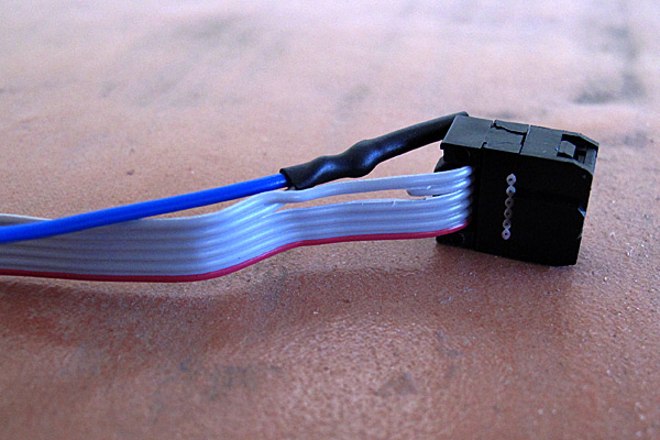
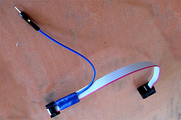
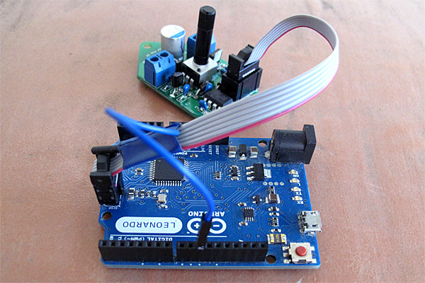
In the evenings this week, I soldered up another PWM controller for the LED lamp projects, and programmed it with the ISP cable I made.  The intent was to use this dimmer either with the breakfast-room lighting fixture (which I’ve not made yet) or reprogram it to act as a strobe rather than a dimmer, to replace the Xenon-tube-based Velleman strobe kit that failed last Thanksgiving.

This project took me much longer than expected, because of stupid mistakes I made:

  • I forgot that there was a silkscreen error on the dimmer boards that I had designed.  The outline for the voltage regulator is flipped, because I had not noticed when reading the spec sheet shows the device from the bottom—I’m used to chip views being from the top.  This is the second time that I’ve soldered a voltage regulator on one of the boards backwards, and had to cut it off and replace it with a new one.  I guess I’d better take a permanent felt-tip marker and draw the correct orientation on the remaining boards, so that I don’t make that mistake a third time.
  • When playing with new code for the strobe, refamiliarizing myself with the ATtiny13A processor, I changed the prescaling on the system clock from the default 1.2MHz down to about 75kHz.  What I had not realized is that the on-chip clock is used during the reprogramming also, and the Arduino ISP is not set up for slowly clocked chips.  I found code for TinyISP, which has code for 128kHz clocks, but even when I modified it for 75kHz clocks I couldn’t reprogram the chip (always getting the “Yikes! invalid device signature” message with a signature of 0). Eventually, I gave up, unsoldered the ATtiny13A and put in a new one.  I’ll be very careful in future not to slow down the system clock so much.
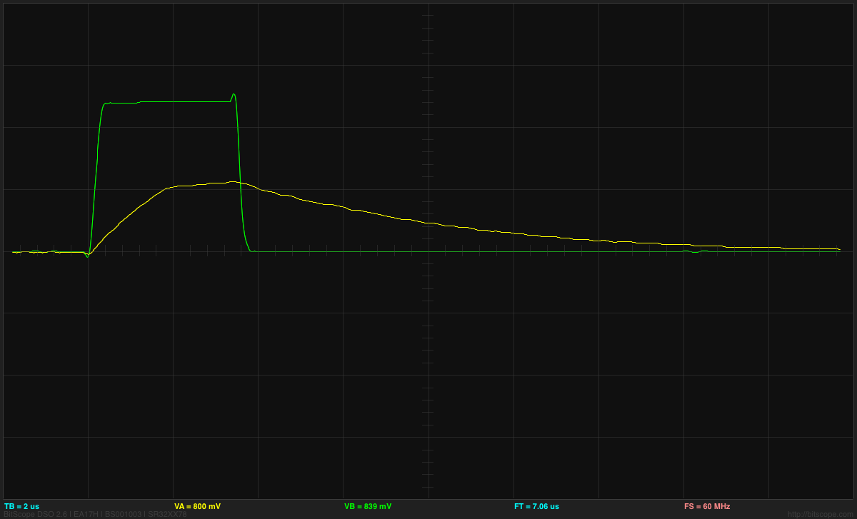
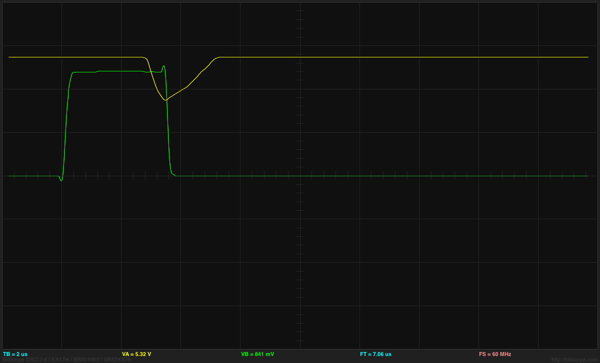
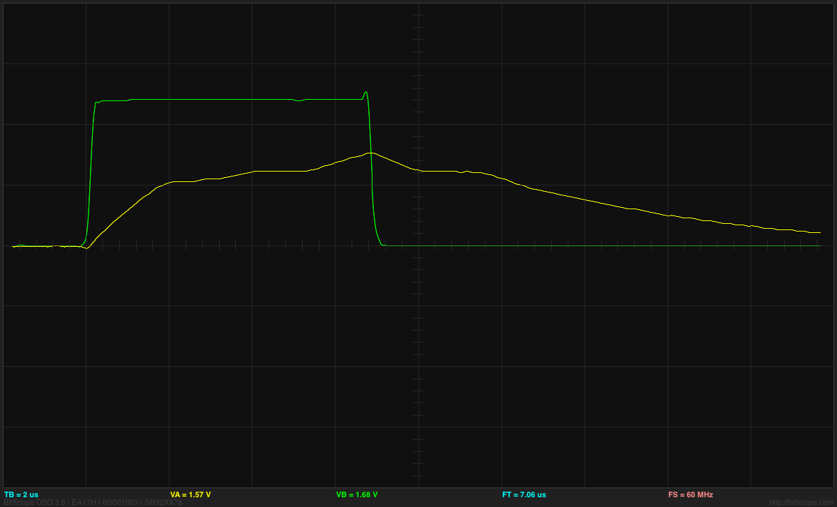
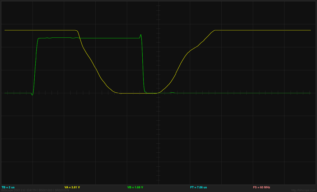
  • I got the strobe working this morning, but when I looked at the output pin that was driving the FET gate, it was only going up to 1.3V, not 5V, and the pulse was much longer than I expected.  This mystified me for a while, but I finally realized that I had forgotten to turn the pin on as an output, so I was driving the output just through the built-in pullup resistor, resulting in a very large RC time constant.  The flat top I was seeing on the pulse was probably the Miller plateau.  Enabling the output pin correctly got me back to crisp 5V pulses of the designed duration.
  • The designed duration for the pulses was a bit too short, resulting in a somewhat dimmer than desired flash.  Lengthening the pulse to 1ms was fine for the slow strobes, but at high flash rates the strobe got too bright. So I reprogrammed the flashes so that the on-time was 1/64th of the off-time, but with a maximum on-time of 1.6ms. (I also tried on=off/128 with a maximum of 1ms, but I liked the 1/64 better).

I timed the strobe pulses from the board (looking at the output of the ATtiny13A pin 6, which is also connected to the MISO pin of the ISP header, so is easy to connect a jumper wire to) with PteroDAQ (through a voltage divider, to drop the voltage from 5V to 2.75V).  By triggering the PteroDAQ on edges of the signal, and averaging many measurements, I got very precise timing measurements:

setup on-time off-time
slowest setting, 1:64 1.63745ms 1.52372s
fastest setting, 1:64 104.958µs 6.98761ms
slowest setting, 1:128 955.277µs 1.55881s
fastest setting, 1:128 51.3123µs 6.99286ms

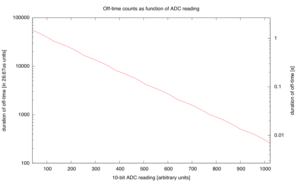
The difference in the “slowest” settings is probably just from my inability to set the knob identically—it has to be just above a threshold below which the strobe doesn’t flash at all. In any case, I have a period from 7.1ms (141Hz) to 1.525s (0.6556Hz), which is a pretty useful range.  I also made the range very smooth, by taking the 10-bit ADC range and converting it to this 215:1 range sort of exponentially with just a few instructions:

if adc<40, then OFF
exp = adc >> 7
frac = 0xff - (adc & 0x7f)
on_time = (frac << 8) >> exp

The tiny number of instructions provides a surprisingly smooth and strictly decreasing approximation to the desired exponential.

The transition is smooth because every time an increment increases the exponent, the frac part is doubled (from 0x80 to 0xff).I use a 16-bit word for the on_time and count it down with an interrupt once every 26.67µs (256 of the approximately 9.6MHz clock ticks). I think that I’ll do a similar thing for controlling the duty cycle of the dimmer, rather than the table of bytes that I currently use, though the duty cycle is limited to a single byte, so I’ll only have 256 levels, and not 1024, and I’ll want the duty cycle to increase exponentially, rather than decreasing, but those are easy fixes.

I also reduced the size of the program in flash, by getting rid of some of the overly general code from core13 and just manipulating the peripheral control registers directly.  I didn’t need to do this, as the ATtiny13A has 1kB of flash, but I got down to 364 bytes (and could probably strip out another 50–100 by getting rid of even more of core13).  The old dimmer code, which doesn’t have much more to do, currently takes 806 bytes, so I might try tightening that up tomorrow.

I also tried powering the strobe off a 9V battery.  The LED board takes about 117mA when turned on (see LED board I-vs-V curve), and if I keep the duty cycle below 1.5%, then the average current is dominated by the ATtiny13A’s worst-case 6mA current, and the total current for the board is probably less than 8mA.  According to Duracell’s data sheet for their 9V alkaline battery, I should be able to get about 50 hours of life before the voltage drops below 6.7V (at which point the LED board no longer maintains the constant current, but I could run the strobe a bit longer getting dimmer).  The 6.7V is also about the voltage where the LDO voltage regulator starts being unable to supply 5V to the ATtiny13A, though that is less of a bottleneck, as the chip can run with the 9.6MHz internal clock down to 3V with no problems.

The battery does not have to provide a full 117mA for the pulses, as there is a 470μF polymer electrolytic capacitor on the dimmer board.  Delivering 117mA for 1.6ms is only 187μC, so the voltage on the capacitor would dip at most 0.4V during the pulse, even without the battery.  The 9V battery has an internal resistance of 2Ω–4Ω, so it could provide 117mA with about a 0.35V drop, so the capacitor isn’t really necessary for one LED board.  It probably increases the efficiency slightly, as the I2R power loss in the internal resistor is reduced if the current is spread out (half the current for twice as long is only half the I2R loss).

I could put more LED boards on the strobe, as the dimmer is designed to handle 5A or more, but battery  operation would limit me to about 10 boards before the voltage drop was large enough to cause problems for the current regulation.  One LED board is bright enough for a Halloween pumpkin, but I could run wires between pumpkins to power several off the same controller.  (I could also keep the controller in the house, powered by a wall wart, and run wires out to the LED boards—I could then power 40 or 50 LED boards off the strobe, though I’d have to watch out for IR drop in the wiring.)

I might try wiring up 10 boards tomorrow, and see whether a battery really can power that many.


Filed under: Uncategorized Tagged: Arduino, Arduino as ISP, ATtiny, dimmable LED lamps, lamp, strobe, stroboscope

Arduino as ISP

For the LED lamp projects, I’ve been using ATtiny13A chips for the dimmer board, programmed with the Arduino IDE and an Arduino board as an In-System Programmer (ISP).  The Arduino code is too big for an ATtiny, so I’ve been using a version of the core13 stripped-down system.

I got rather tired of wiring up the 8 wires for the ISP, checking to make sure that each one was correct.  What I wanted to do was just plug in a standard 8-pin cable from the Arduino board to the ATtiny board, but the ISP header on the Arduino board has the Arduino reset line, not the reset line that has to go to the ATtiny board.

I decided to modify a standard cable to do the right thing, separating the reset line from the rest. The reset line is on pin 7, so on a standard ribbon cable, it is the seventh of the eight wires.

First I carefully cut wire 7 near one of the plugs with a razor knife, peeled it back and spliced on another piece of stranded wire:

The blue wire and wire 7 of the ribbon cable were soldered together and covered with heat-shrink tubing.

I taped the soldered joint to rest of the ribbon cable for strain relief, and added a crimp-on female header at the other end. (I prefer female crimp-on headers, because they are more versatile than male pin—I can stick in a double-ended male header pin to convert them to male connectors when needed.)

The electrical tape stabilizes the splice and the crimp-on female header allows connecting to male or female headers on the Arduino board. Here there is a double-ended male header pin in the female header, to convert it to a male header.

Here is a Leonardo board being used to program one of the dimmer boards:

With the new cable, it is easy to unplug the cable after programming to test out the system, then plug it back in with the right orientation (I used a shrouded header on the dimmer board) when reprogramming is needed.

Note that the reset line for the ISP cable connects to pin 10 of the programming Arduino board, which would be connected via a USB cable to the laptop that has the Arduino development environment on it.

I’ve seen several kluges on the web for connecting up Arduinos as ISPs, but none were as simple as and easy to use as what I did here, so I thought I ought to share it.


Filed under: Uncategorized Tagged: Arduino, Arduino as ISP, ATtiny, dimmable LED lamps, lamp

Arduino IDE 1.6.2 released, featuring cores and libraries manager

A new version of the Arduino IDE (1.6.2) is available at the download page!

1.6.2 includes a very long awaited feature: boards and libraries one click install.

With 1.6.2, two new menu items are available: “Sketch > Include Library > Manage Libraries…” and “Tools > Board > Boards Manager…”

We have written two guides that explain how to use them. Discover how to use the Library Manager and how to install support for additional boards.

If you don’t find your preferred library in the list, let us know: open an issue on github and request us to add the library you love!

Having such tools allow us to better and easier deliver updates for both cores and libraries: just open Library Manager or Boards Manager to find an Update button on the updatable items.

IDE 1.6.2 also includes a handful of bug fixes and improvements, also thanks to our fantastic community of hackers and makers:

  • Ever suffered of a super slow Tools menu? Solved! Ports list gets refreshed in background, so you won’t need to wait any more.
  • We have dropped support for Mac OS X 10.6 or older: previous versions of the IDE will remain available for download at the previous releases page.
  • A new EEPROM library, thanks to @Chris–A
  • Pre and post build hooks, thanks to @Wackerbarth
  • Various bug fixes, thanks to @Timmmm, @vicatcu, @arve0 and @Xuth

As usual, the complete list of fixes and credits is available here.

Don’t forget to report any issue you find, either on Github or on the Arduino forum: your help is very much appreciated. It doesn’t matter if you are not a tech specialist: every feedback adds value.

We are already working on release 1.6.2, with some very useful features and user experience improvements. Stay tuned!

Arduino Blog 27 Mar 12:58

E-traces creates visual sensations from ballerinas

Electronic Traces is an interactive project designed to allow ballet dancers to recreate their movements in  digital pictures using a customizable mobile application. It was prototyped by product-designer Lesia Trubat mixing technological, artisanal skills and using Arduino Lilypad, force sensitive resistors and accelerometer:

The concept of Electronic Traces is based on capturing dance movements and transforming them into visual sensations through the use of new technologies. To do this we focused on the ballet shoes themselves, which through the contact with the ground, and thanks to Lilypad Arduino technology, record the pressure and movement of the dancer’s feet and send a signal to an electronic device. A special application will then allow us to show this data graphically and even customize it to suit each user, through the different functions of this app.

The user can then view all the moves made in video format, extract images and even print them. Dancers can interpret their own movements and correct them or compare them with the movements of other dancers, as graphs created with motion may be the same or different depending on the type of movements execute.


Sound Camera.


One more project, that shows breathtaking beauty of the FFT (Fast Fourier Transform). Once again, like in last 3D Ultrasonic Radar Project,    Arduino DUE was nominated to be Maestro, doing major part of the Digital Signal Processing in real time.  As you can see below, the hardware includes 4 “modules”:

  1. Sensor board
  2. Arduino DUE
  3. Bluetooth shield
  4. Android tablet.

Last two items aren’t strictly necessary. Alternative would be to connect TFT display directly to arduino, but I decided not to spend my time on re-inventing drawing-rendering software. Better to delegate all visualization stuff to the equipment that was  specifically design by big monsters in high tech industry.  I spend quite time digging into android graphics subject anyway, only hoping I can apply my knowledge somewhere else later on.

Sensor board holds 4 microphones from  SFE.  Plus a few decoupling components, capacitors and inductor in power line.

Software.

   Brief summary: Arduino sampling 4 analog inputs, close to 41 kHz,  x 4 = 164 ksps,  software library Radix4 posted on this blog was imported into project practically intact. DMA feature on Arduino DUE allows sampling rate up to 1 MSPS, and I already successfully tested its capability in 3D Radar project.  Having 2048 fft size, at the first processing stage  output there are 1024 bins 20 Hz each. Than, using arctangent LUT, phase of each bin is extracted.  Difference in phases two vertically position microphones gives Y component, and two horizontally spaced mic’s – X component. Sound source is localized with accuracy ~ 0.5 degree. Have to say, that on the lower frequency end, 100 Hz – 1 kHz , where wavelength is huge compare to spacing between two mic’s ( 3.4 meters at 100 Hz ), accuracy is deteriorating proportionally to wavelength.

Arduino is calculating data really fast, providing  X,  Y, and M  every 50 milliseconds. M – is for magnitude. Than, all this data stream flows to android over BT.  Everything else is obvious, watch the video.

Speaker outputs white noise, as for single tone (frequency) only one pixel would be visible on screen. Android software “colorized” picture based on a frequency, low range – starting from red, and up to violet on high end of the frequency band, through all 1024 color wheel possibilities.  You can see, that picture saturated with green and blue, and there is almost no red color. There are two things, first is a speaker, not performing well at low end. Second nuance is the fact, that low frequencies are not “grouped” so effectively, due to the localization error, what I tried to explain in a paragraph above. I created an option in the menu to select different types of colorization, based on a frequency or based on a magnitude. They are look pretty similar for white noise source, so there is only one video clip.

Have fun.


 Edited on 21 Oct. 2014:

 If you come across this page searching an old  “Localizator” project, published over 2 years ago, here is working material I was able to find:   Localizator.