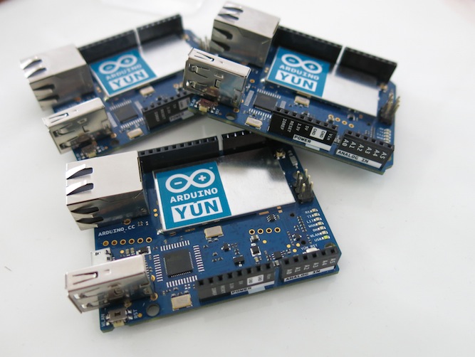
First things: there are no servo motors. No motors or any mechanical moving parts in this project.
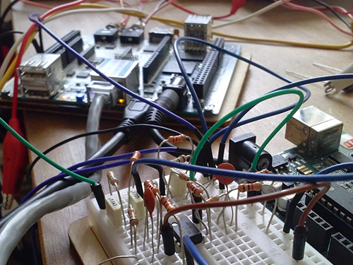
There are 4 HC-SR04 ultrasonic sensor units, only one is working as transmitting – pinging module and receiver simultaneously, 3 others are just receivers. Arduino DUE, of course, is a prime violin of the whole project. Small prototype board has an additional 4-channel buffer amplifier (MCP6024).
Technical specification ( approximately ):
- Scanning range 3 m, limited very low power and sensitivity of the HC-SR04 devices.
- Spacial XY resolution depends on a distance, has to be determined. Two object should be position at least 5 cm apart and not on the same spherical surface around sensor board.
- Directivity diagram +-30 degree, or so.
- Spacial Z – (distance) resolution 12 um. No typo error, micrometers.
- Time to complete full scan 16 milliseconds, frame rate may vary from 60 Hz down to 10 Hz if there is strong reverberation.
Have to say, that ultrasonic units were slightly modified, to brought out an analog signal (40 kHz) before it gets quantization in the local uCPU. After amplification, 4-channels are digitized by arduino’s ADC (12-bits 1 MSPS).
Fast Fourier Transform, not much differs from the published on this blog library. I’m not ready to disclose complete signal processing algorithm, and is not publishing a code, at this time. Nevertheless, I don’t mind to answer reasonable /meaningful questions.
Video: have to practice more -);
A few comments on a video clip. I intentionally use a pen to draw a picture, even it’s almost violate the basic of the physics, because reflective area of the pen practically equals to wave length, 8.5 mm for 40 kHz in the air. You can see, that arduino is loosing track on a few occasions. Distance ~ 1m.
Computer is running Linux with regular “mtPaint 3.40″ from official source. Software is receiving a mouse commands, as its has no idea where this commands come from. In the same way, if you draw a picture manually. To interface with a host, arduino emulates a left button and XY move mouse commands using “build-in” mouse driver, and I copy ButtonMouseControl example from IDE.
The surface of the touch screen is “virtual”, first things arduino does after I send a command over serial monitor console to start a drawing, is “search – scan” an object. Whatever it finds first, the closest one, would be “locked” and distance to this object is interpreted as “touched – untouched”. This is first try, and I was not pushing hard on the gesture pattern recognition yet. But as you can guess, there is no limits to “slide” “rotate” “scroll” etc movement discrimination, with only one exception. There is no “multi-touch”, as I mentioned in the specification section, two object has to be 5 cm apart. This limitation is introduced by two shortcomings of the current hardware design. First one, because there is no phase array, only one unit is transmitting ( in the middle on right side ), so there is no way arduino could identify two objects on the same sphere. Second, is low sampling rate of the ADC. In order to “shrink” XY spatial resolution down to wave length (8.5 mm), sampling rate has to be at least 6 MSPS or so.
Tracking update rate (scan frame rate – don’t confuse with a video) is set to 32 fps.
Photo:


eddited: 14 Aug. 2014 “New technology is rising!”
Second video clip is posted, that demonstrates better tracking stability over bigger distance range.
Distance is 1.2 m, same pen. I think, that all for Virtual Touch Screen demonstration. Any improvements I could make in a code ‘d introduced only small changes in overall representativity of the project.
This HID technology is completely new area for me, and I’m not a professional programmer. Be curious, I look into “regular” touch screen (resistive – capacitive) library free accessible on the i-net. I find over 100 variables that initialized and updated in order to keep track on a bunch of real-time parameters, that “normal” TS supplies with 10 ms time interval. Another 100′s variables are buried inside proprietary driver in the OS. It would takes a years to run a test and debug effects each of this variables on stability, smoothness, susceptibility etc. And moreover, my invention Virtual TS – 3D would require a lot more than a 100′s….
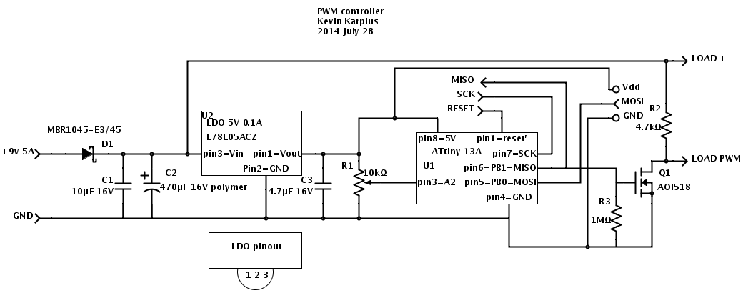
edited: 26 Aug. 2014 Answering the question, modification to HC-SR04 module.
There is an electrical drawings, I was able to locate on-line:
http://uglyduck.ath.cx/HC-SR04E/HC-SR04E.svgz
And photo: 
As you can see, analog 40 kHz output is taken from pin 7, LM324. Conveniently, it’s the rightest one, close to the board edge. Module – transmitter has a jumper wire over B-E of the transistor, others 3 units may not have this wire. I find out, that unit doesn’t transmit anything till it gets a response, that may never happened for echo reflected from tiny object like a pen. It looks like on-board uCPU is waiting a transition in poling mode. And additional amplification stage I build with MCP6024, is similar to first stage of the LM324 (U2D), with a gain x50. In my first try, I connect output of LM324 directly to arduino DUE analog inputs, basically its not realy safe, as voltage goes close to 3.6-3.7 V. But than introducing MCP6024 (rail-to-rail) I decrease power voltage of the OPA down to 3.3V, not to worry about my DUE.