Introduction:
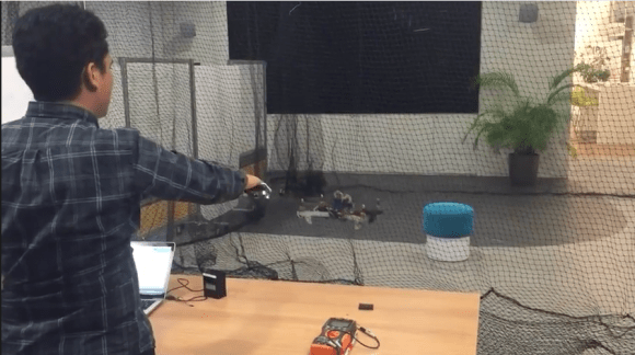
The HC-SR04 Ultrasonic Sensor is a very affordable proximity/distance sensor that has been used mainly for object avoidance in various robotics projects . It essentially gives your Arduino eyes / spacial awareness and can prevent your robot from crashing or falling off a table. It has also been used in turret applications, water level sensing, and even as a parking sensor. This simple project will use the HC-SR04 sensor with an Arduino and a Processing sketch to provide a neat little interactive display on your computer screen.
 Parts Required:Freetronics Eleven
 or any compatible Arduino.
HC-SR04 Ultrasonic Sensor
Mini Breadboard 4.5cm x 3.5cm
Protoshieldand female header pins (not essential - but makes it more tidy)
Wiresto connect it all together
The Video:The Arduino Sketch: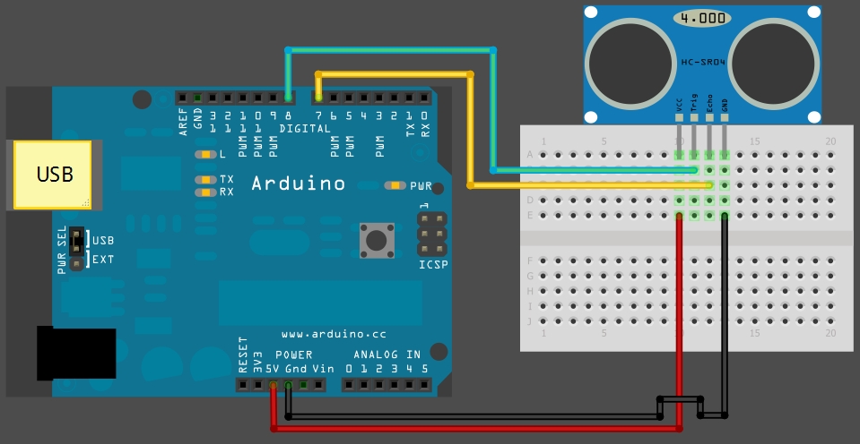 The above sketch was created using Fritzing.Arduino Code:
You can download the Arduino IDE from
this site.
 1
 2
 3
 4
 5
 6
 7
 8
 9
10
11
12
13
14
15
16
17
18
19
20
21
22
23
24
25
26
27
28
29
30
31
32
33
34
35
36
37
38
39
40
41
42
43
44
45
46
47
48
49
50
51
52
53
54
55
56
57
58
59
60 | /*
HC-SR04 Ping distance sensor:
VCC to arduino 5v
GND to arduino GND
Echo to Arduino pin 7
Trig to Arduino pin 8
This sketch originates from Virtualmix: http://goo.gl/kJ8Gl
Has been modified by Winkle ink here: http://winkleink.blogspot.com.au/2012/05/arduino-hc-sr04-ultrasonic-distance.html
And modified further by ScottC here: http://arduinobasics.blogspot.com.au/2012/11/arduinobasics-hc-sr04-ultrasonic-sensor.html
on 10 Nov 2012.
*/
#define echoPin 7 // Echo Pin
#define trigPin 8 // Trigger Pin
#define LEDPin 13 // Onboard LED
int maximumRange = 200; // Maximum range needed
int minimumRange = 0; // Minimum range needed
long duration, distance; // Duration used to calculate distance
void setup() {
Serial.begin (9600);
pinMode(trigPin, OUTPUT);
pinMode(echoPin, INPUT);
pinMode(LEDPin, OUTPUT); // Use LED indicator (if required)
}
void loop() {
/* The following trigPin/echoPin cycle is used to determine the
distance of the nearest object by bouncing soundwaves off of it. */
digitalWrite(trigPin, LOW);
delayMicroseconds(2);
digitalWrite(trigPin, HIGH);
delayMicroseconds(10);
digitalWrite(trigPin, LOW);
duration = pulseIn(echoPin, HIGH);
//Calculate the distance (in cm) based on the speed of sound.
distance = duration/58.2;
if (distance >= maximumRange || distance <= minimumRange){
/* Send a negative number to computer and Turn LED ON
to indicate "out of range" */
Serial.println("-1");
digitalWrite(LEDPin, HIGH);
}
else {
/* Send the distance to the computer using Serial protocol, and
turn LED OFF to indicate successful reading. */
Serial.println(distance);
digitalWrite(LEDPin, LOW);
}
//Delay 50ms before next reading.
delay(50);
} |
You can download the Processing IDE from
this site.
 1
 2
 3
 4
 5
 6
 7
 8
 9
 10
 11
 12
 13
 14
 15
 16
 17
 18
 19
 20
 21
 22
 23
 24
 25
 26
 27
 28
 29
 30
 31
 32
 33
 34
 35
 36
 37
 38
 39
 40
 41
 42
 43
 44
 45
 46
 47
 48
 49
 50
 51
 52
 53
 54
 55
 56
 57
 58
 59
 60
 61
 62
 63
 64
 65
 66
 67
 68
 69
 70
 71
 72
 73
 74
 75
 76
 77
 78
 79
 80
 81
 82
 83
 84
 85
 86
 87
 88
 89
 90
 91
 92
 93
 94
 95
 96
 97
 98
 99
100
101
102
103
104
105
106
107
108
109
110
111
112
113
114
115
116
117
118
119
120
121
122
123
124
125
126
127
128 | /* The following Processing Sketch was created by ScottC on
the 10 Nov 2012 : http://arduinobasics.blogspot.com/
Inspired by this Processing sketch by Daniel Shiffman:
http://processing.org/learning/basics/sinewave.html
*/
import processing.serial.*;
int numOfShapes = 60; // Number of squares to display on screen
int shapeSpeed = 2; // Speed at which the shapes move to new position
// 2 = Fastest, Larger numbers are slower
//Global Variables
Square[] mySquares = new Square[numOfShapes];
int shapeSize, distance;
String comPortString;
Serial myPort;
/* -----------------------Setup ---------------------------*/
void setup(){
size(displayWidth,displayHeight); //Use entire screen size.
smooth(); // draws all shapes with smooth edges.
/* Calculate the size of the squares and initialise the Squares array */
shapeSize = (width/numOfShapes);
for(int i = 0; i<numOfShapes; i++){
mySquares[i]=new Square(int(shapeSize*i),height-40);
}
/*Open the serial port for communication with the Arduino
Make sure the COM port is correct - I am using COM port 8 */
myPort = new Serial(this, "COM8", 9600);
myPort.bufferUntil('\n'); // Trigger a SerialEvent on new line
}
/* ------------------------Draw -----------------------------*/
void draw(){
background(0); //Make the background BLACK
delay(50); //Delay used to refresh screen
drawSquares(); //Draw the pattern of squares
}
/* ---------------------serialEvent ---------------------------*/
void serialEvent(Serial cPort){
comPortString = cPort.readStringUntil('\n');
if(comPortString != null) {
comPortString=trim(comPortString);
/* Use the distance received by the Arduino to modify the y position
of the first square (others will follow). Should match the
code settings on the Arduino. In this case 200 is the maximum
distance expected. The distance is then mapped to a value
between 1 and the height of your screen */
distance = int(map(Integer.parseInt(comPortString),1,200,1,height));
if(distance<0){
/*If computer receives a negative number (-1), then the
sensor is reporting an "out of range" error. Convert all
of these to a distance of 0. */
distance = 0;
}
}
}
/* ---------------------drawSquares ---------------------------*/
void drawSquares(){
int oldY, newY, targetY, redVal, blueVal;
/* Set the Y position of the 1st square based on
sensor value received */
mySquares[0].setY((height-shapeSize)-distance);
/* Update the position and colour of each of the squares */
for(int i = numOfShapes-1; i>0; i--){
/* Use the previous square's position as a target */
targetY=mySquares[i-1].getY();
oldY=mySquares[i].getY();
if(abs(oldY-targetY)<2){
newY=targetY; //This helps to line them up
}else{
//calculate the new position of the square
newY=oldY-((oldY-targetY)/shapeSpeed);
}
//Set the new position of the square
mySquares[i].setY(newY);
/*Calculate the colour of the square based on its
position on the screen */
blueVal = int(map(newY,0,height,0,255));
redVal = 255-blueVal;
fill(redVal,0,blueVal);
/* Draw the square on the screen */
rect(mySquares[i].getX(), mySquares[i].getY(),shapeSize,shapeSize);
}
}
/* ---------------------sketchFullScreen---------------------------*/
// This puts processing into Full Screen Mode
boolean sketchFullScreen() {
return true;
}
/* ---------------------CLASS: Square ---------------------------*/
class Square{
int xPosition, yPosition;
Square(int xPos, int yPos){
xPosition = xPos;
yPosition = yPos;
}
int getX(){
return xPosition;
}
int getY(){
return yPosition;
}
void setY(int yPos){
yPosition = yPos;
}
} |
However, if you do not have a google profile...
Feel free to share this page with your friends in any way you see fit.