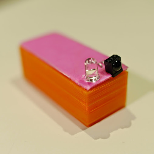
We keep getting requests on how to use DS1307 and DS3231 real-time clock modules with Arduino from various sources – so this is the first of a two part tutorial on how to use them. For this Arduino tutorial we have two real-time clock modules to use, one based on the Maxim DS1307:

and another based on the DS3231:

There are two main differences between the ICs on the real-time clock modules, which is the accuracy of the time-keeping. The DS1307 used in the first module works very well, however the external temperature can affect the frequency of the oscillator circuit which drives the DS1307’s internal counter.
This may sound like a problem, however will usually result with the clock being off by around five or so minutes per month. The DS3231 is much more accurate, as it has an internal oscillator which isn’t affected by external factors – and thus is accurate down to a few minutes per year at the most. If you have a DS1307 module- don’t feel bad, it’s still a great value board and will serve you well.
With both of the modules, a backup battery is installed when you receive them from Tronixlabs, however these are an inexpensive variety and shouldn’t be relied on for more than twelve months. If you’re going to install the module in a more permanent project, its’ a good idea to buy a new CR2023 battery and fit it to the module.
Along with keeping track of the time and date, these modules also have a small EEPROM, an alarm function (DS3231 only) and the ability to generate a square-wave of various frequencies – all of which will be the subject of a second tutorial.
Connecting your module to an Arduino
Both modules use the I2C bus, which makes connection very easy. If you’re not sure about the I2C bus and Arduino, check out the I2C tutorials (chapters 20 and 21), or review chapter seventeen of my book “Arduino Workshop“.
Moving on – first you will need to identify which pins on your Arduino or compatible boards are used for the I2C bus – these will be knows as SDA (or data) and SCL (or clock). On Arduino Uno or compatible boards, these pins are A4 and A5 for data and clock:

If you’re using an Arduino Mega the pins are D20 and D21 for data and clock:

If you’re using an Pro Mini-compatible the pins are A4 and A5 for data and clock, which are parallel to the main pins, as shown below:

DS1307 module
If you have the DS1307 module you will need to solder the wires to the board, or solder on some inline header pins so you can use jumper wires. Then connect the SCL and SDA pins to your Arduino, and the Vcc pin to the 5V pin and GND to GND.
DS3231 module
Connecting this module is easy as header pins are installed on the board at the factory. You can simply run jumper wires again from SCL and SDA to the Arduino and again from the module’s Vcc and GND pins to your board’s 5V or 3.3.V and GND. However these are duplicated on the other side for soldering your own wires.
Both of these modules have the required pull-up resistors, so you don’t need to add your own. Like all devices connected to the I2C bus, try and keep the length of the SDA and SCL wires to a minimum.
Reading and writing the time from your RTC Module
Once you have wired up your RTC module. enter and upload the following sketch. Although the notes and functions in the sketch refer only to the DS3231, the code also works with the DS1307.
#include "Wire.h"
#define DS3231_I2C_ADDRESS 0x68
// Convert normal decimal numbers to binary coded decimal
byte decToBcd(byte val)
{
  return( (val/10*16) + (val%10) );
}
// Convert binary coded decimal to normal decimal numbers
byte bcdToDec(byte val)
{
  return( (val/16*10) + (val%16) );
}
void setup()
{
  Wire.begin();
  Serial.begin(9600);
  // set the initial time here:
  // DS3231 seconds, minutes, hours, day, date, month, year
  // setDS3231time(30,42,21,4,26,11,14);
}
void setDS3231time(byte second, byte minute, byte hour, byte dayOfWeek, byte
dayOfMonth, byte month, byte year)
{
  // sets time and date data to DS3231
  Wire.beginTransmission(DS3231_I2C_ADDRESS);
  Wire.write(0); // set next input to start at the seconds register
  Wire.write(decToBcd(second)); // set seconds
  Wire.write(decToBcd(minute)); // set minutes
  Wire.write(decToBcd(hour)); // set hours
  Wire.write(decToBcd(dayOfWeek)); // set day of week (1=Sunday, 7=Saturday)
  Wire.write(decToBcd(dayOfMonth)); // set date (1 to 31)
  Wire.write(decToBcd(month)); // set month
  Wire.write(decToBcd(year)); // set year (0 to 99)
  Wire.endTransmission();
}
void readDS3231time(byte *second,
byte *minute,
byte *hour,
byte *dayOfWeek,
byte *dayOfMonth,
byte *month,
byte *year)
{
  Wire.beginTransmission(DS3231_I2C_ADDRESS);
  Wire.write(0); // set DS3231 register pointer to 00h
  Wire.endTransmission();
  Wire.requestFrom(DS3231_I2C_ADDRESS, 7);
  // request seven bytes of data from DS3231 starting from register 00h
  *second = bcdToDec(Wire.read() & 0x7f);
  *minute = bcdToDec(Wire.read());
  *hour = bcdToDec(Wire.read() & 0x3f);
  *dayOfWeek = bcdToDec(Wire.read());
  *dayOfMonth = bcdToDec(Wire.read());
  *month = bcdToDec(Wire.read());
  *year = bcdToDec(Wire.read());
}
void displayTime()
{
  byte second, minute, hour, dayOfWeek, dayOfMonth, month, year;
  // retrieve data from DS3231
  readDS3231time(&second, &minute, &hour, &dayOfWeek, &dayOfMonth, &month,
  &year);
  // send it to the serial monitor
  Serial.print(hour, DEC);
  // convert the byte variable to a decimal number when displayed
  Serial.print(":");
  if (minute<10)
  {
    Serial.print("0");
  }
  Serial.print(minute, DEC);
  Serial.print(":");
  if (second<10)
  {
    Serial.print("0");
  }
  Serial.print(second, DEC);
  Serial.print(" ");
  Serial.print(dayOfMonth, DEC);
  Serial.print("/");
  Serial.print(month, DEC);
  Serial.print("/");
  Serial.print(year, DEC);
  Serial.print(" Day of week: ");
  switch(dayOfWeek){
  case 1:
    Serial.println("Sunday");
    break;
  case 2:
    Serial.println("Monday");
    break;
  case 3:
    Serial.println("Tuesday");
    break;
  case 4:
    Serial.println("Wednesday");
    break;
  case 5:
    Serial.println("Thursday");
    break;
  case 6:
    Serial.println("Friday");
    break;
  case 7:
    Serial.println("Saturday");
    break;
  }
}
void loop()
{
  displayTime(); // display the real-time clock data on the Serial Monitor,
  delay(1000); // every second
}
There may be a lot of code, however it breaks down well into manageable parts.
It first includes the Wire library, which is used for I2C bus communication, followed by defining the bus address for the RTC as 0x68. These are followed by two functions that convert decimal numbers to BCD (binary-coded decimal) and vice versa. These are necessary as the RTC ICs work in BCD not decimal.
The function setDS3231time() is used to set the clock. Using it is very easy, simple insert the values from year down to second, and the RTC will start from that time. For example if you want to set the following date and time – Wednesday November 26, 2014 and 9:42 pm and 30 seconds – you would use:
setDS3231time(30,42,21,4,26,11,14);
Note that the time is set using 24-hour time, and the fourth paramter is the “day of week”. This falls between 1 and 7 which is Sunday to Saturday respectively. These parameters are byte values if you are subsituting your own variables.
Once you have run the function once it’s wise to prefix it with // and upload your code again, so it will not reset the time once the power has been cycled or micrcontroller reset.
Reading the time form your RTC Is just as simple, in fact the process can be followed neatly inside the function displayTime(). You will need to define seven byte variables to store the data from the RTC, and these are then inserted in the function readDS3231time().
For example if your variables are:
byte second, minute, hour, dayOfWeek, dayOfMonth, month, year;
… you would refresh them with the current data from the RTC by using:
readDS3232time(&second, &minute, &hour, &dayOfWeek, &dayOfMonth, &month, &year);
Then you can use the variables as you see fit, from sending the time and date to the serial monitor as the example sketch does – to converting the data into a suitable form for all sorts of output devices.
Just to check everything is working, enter the appropriate time and date into the demonstration sketch, upload it, comment out the setDS3231time() function and upload it again. Then open the serial monitor, and you should be provided with a running display of the current time and date, for example:

From this point you now have the software tools to set data to and retrieve it from your real-time clock module, and we hope you have an understanding of how to use these inexpensive modules.
You can learn more about the particular real-time clock ICs from the manufacturer’s website – DS1307 and DS3231.
And if you enjoyed this article, or want to introduce someone else to the interesting world of Arduino – check out my book (now in a fourth printing!) “Arduino Workshop”.

Have fun and keep checking into tronixstuff.com. Why not follow things on twitter, Google+, subscribe for email updates or RSS using the links on the right-hand column, or join our forum – dedicated to the projects and related items on this website.
The post Tutorial – Using DS1307 and DS3231 Real-time Clock Modules with Arduino appeared first on tronixstuff.