Posts with «servo» label

NFC Ring Lock Box

[Nairod785] wanted to build a lock box that would lock from the inside. He started with an inexpensive, plain wooden box. This kept the cost down but would also allow him to easily decorate the box later on using a wood burning tool.

To keep the box locked, he installed a simple latch on the inside. The latch is connected to a servo with string. When the servo rotates in one direction, it pulls the string and releases the latch. When the servo is rotated in the opposite direction, the latch closes and locks the box once again.

If you are going to have a locked box, then you are also going to need a key to open it. [Nairod785] used a ring with a built-in NFC tag, similar to the ring featured back in March. Inside of the box is a PN532 NFC module. The walls of the box were a little too thick for the reader to detect the ring, so [Nairod785] had to scratch the wall thickness down a bit. The NFC module is connected to an Arduino Nano. Communications are handled with I2C.

The NFC ring actually has two different NFC tags in it; one on each side. [Nairod785] had to program both of the tag ID’s into the Arduino to ensure that the ring would work no matter the orientation.

The system is powered by a small rechargeable 5V battery. [Nairod785] wired up a USB plug flush with the box wall so he can easily charge up the battery while the box is locked. It also allows him to reprogram the Arduino if he feels so inclined. There is also a power switch on the side to conserve energy.


Filed under: Arduino Hacks
Hack a Day 10 Aug 15:00
arduino  arduino hacks  lock box  nano  nfc  pn532  ring  servo  

Creeper

Primary image

What does it do?

Navigate around via ultrasound or controlled by bluetooth

Inspired by this one: http://www.instructables.com/id/Strandbot-a-solar-arduino-powered-RC-motorize/ Autonomous walker, based on a model of the strandbeest. This unit runs on 20rpm 6 volt motors and walks real slow. On the other hand, it's very silent. Due to it's sweeping sensor it can run autonomous, but it can also be controlled with a bluetooth enabled device. On the front a small speaker, connected to a voice record and playback chip; when it runs into something, it does a Uh-Oh :)


Things still to work on:

- give it a paint job

Cost to build

$40,00

Embedded video

Finished project

Number

Time to build

10 hours

Type

legs

URL to more information

Weight

350 grams

read more

Tutorial – Arduino and the TLC5940 PWM LED Driver IC

Use the Texas Instruments TLC5940 16-Channel LED Driver IC with Arduino in Chapter 57 of our Arduino Tutorials. The first chapter is here, the complete series is detailed here.

Introduction

Today we are going to examine the Texas Instruments TLC5940 16-channel LED driver IC. Our reason for doing this is to demonstrate another, easier way of driving many LEDs – and also servos.  First up, here is a few examples of the TLC5940

The TLC5940 is available in the DIP version above, and also surface-mount. It really is a convenient part, allowing you to adjust the brightness of sixteen individual LEDs via PWM (pulse-width modulation) – and you can also daisy-chain more than one TLC5940 to control even more.

During this tutorial we’ll explain how to control one or more TLC5940 ICs with LEDs and also look at controlling servos. At this point, please download a copy of the TLC5940_data_sheet (.pdf) as you will refer to it through this process. Furthermore, please download and install the TLC5940 Arduino library by Alex Leone which can be found here. If you’re not sure how to install a library, click here.

Build a TLC5940 demonstration circuit

The following circuit is the minimum required to control sixteen LEDs from your Arduino or compatible. You can use it to experiment with various functions and get an idea of what is possible. You will need:

  • An Arduino Uno or compatible board
  • 16 normal, everyday LEDs that can have a forward current of up to 20 mA
  • a 2 kΩ resistor (give or take 10%)
  • a 0.1uF ceramic and a 4.7uF electrolytic capacitor

Take note of the LED orientation – and remember the TLC5940 is a common-anode LED driver – so all the LED anodes are connected together and then to 5V:

For this particular circuit, you won’t need an external 5V power supply – however you may need one in the future. The purpose of the resistor is to control the amount of current that can flow through the LEDs. The required resistor value is calculated with the following formula:

R = 39.06 / Imax

where R (in Ohms)  is the resistor value and Imax (in Amps) is the maximum amount of current you want to flow through the LEDs. For example, if you have LEDs with a 20 mA forward current – the resistor calculation would be:

R = 39.06 / 0.02 = 1803 Ohms.

Once you have the circuit assembled – open up the Arduino IDE and upload the sketch BasicUse.pde  which is in the example folder for the TLC5940 library. You should be presented with output similar to what is shown in the following video:

Controlling the TLC5940

Now that the circuit works, how do we control the TLC5940? First, the mandatory functions – include the library at the start of the sketch with:

#include "Tlc5940.h"

and then initialise the library by placing the following into void setup():

Tlc.init(x);

x is an optional parameter – if you want to set all the channels to a certain brightness as soon as the sketch starts, you can insert a value between 0 and 4095 for in the Tlc.init() function.

Now to turn a channel/LED on or off. Each channel is numbered from 0 to 15, and each channel’s brightness can be adjusted between 0 and 4095.

This is a two-part process…

First – use one or more of the following functions to set up the required channels and respective brightness (PWM level):

Tlc.set(channel, brightness);

For example, if you wanted to have the first three channels on at full brightness, use:

Tlc.set(0, 4095);
Tlc.set(1, 4095);
Tlc.set(2, 4095);

The second part is to use the following to update the TLC5940 with the required instructions from part one:

Tlc.update();

If you want to turn off all channels at once, simply use:

Tlc.clear();

You don’t need to call a TLC.update() after the clear function. The following is a quick example sketch that sets the brightness/PWM values of all the channels to different levels:

#include "Tlc5940.h"
void setup()
{
  Tlc.init(0); // initialise TLC5940 and set all channels off
}

void loop()
{
  for (int i = 0; i < 16; i++)
  {
    Tlc.set(i, 1023);
  }
  Tlc.update();
  delay(1000);
  for (int i = 0; i < 16; i++)
  {
    Tlc.set(i, 2046);
  }
  Tlc.update();
  delay(1000);
  for (int i = 0; i < 16; i++)
  {
    Tlc.set(i, 3069);
  }
  Tlc.update();
  delay(1000);
  for (int i = 0; i < 16; i++)
  {
    Tlc.set(i, 4095);
  }
  Tlc.update();
  delay(1000);
}

and the sketch in action:

The ability to control individual brightness for each channel/LED can also be useful when controlling RGB LEDs – you can then easily select required colours via different brightness levels for each element.

Using two or more TLC5940s

You can daisy-chain quite a few TLC5940s together to control more LEDs. First – wire up the next TLC5940 to the Arduino as shown in the demonstration circuit – except connect the SOUT pin (17) of the first TLC5940 to the SIN pin (26) of the second TLC5940 – as the data travels from the Arduino, through the first TLC5940 to the second and so on. Then repeat the process if you have a third, etc. Don’t forget the resisotr that sets the current!

Next, open the file tlc_config.h located in the TLC5940 library folder. Change the value of NUM_TLCS to the number of TLC5940s you have connected together, then save the file and also delete the file Tlc5940.o also located in the same folder. Finally restart the IDE. You can then refer to the channels of the second and further TLC5940 sequentially from the first. That is, the first is 0~15, the second is 16~29, and so on.

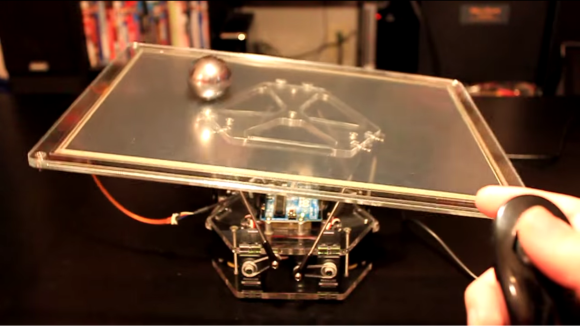
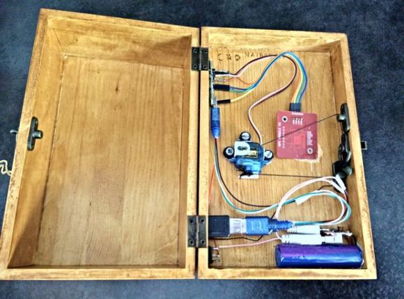
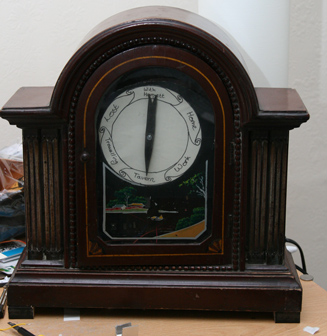
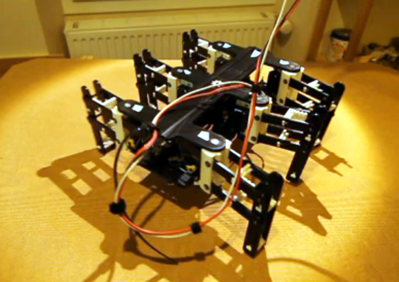
Controlling servos with the TLC5940

As the TLC5940 generates PWM (pulse-width modulation) output, it’s great for driving servos as well. Just like LEDs – you can control up to sixteen at once. Ideal for creating spider-like robots, strange clocks or making some noise. When choosing your servo, ensure that it doesn’t draw more than 120 mA when operating (the maximum current per channel) and also heed the “Managing current and heat” section at the end of this tutorial. And use external power with servos, don’t rely on the Arduino’s 5V line.

To connect a servo is simple – the GND line connects to GND, the 5V (or supply voltage lead) connects to your 5v (or other suitable supply) and the servo control pin connects to one of the TLC5940’s outputs. Finally – and this is important – connect a 2.2kΩ resistor between the TLC5940 output pin(s) being used and 5V.

Controlling a servo isn’t that different to an LED. You need the first two lines at the start of the sketch:

#include "Tlc5940.h"
#include "tlc_servos.h"

then the following in void setup():

tlc_initServos();

Next, use the following function to select which servo (channel) to operate and the required angle (angle):

tlc_setServo(channel, angle);

Just like the LEDs you can bunch a few of these together, and then execute the command with:

Tlc.update();

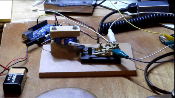
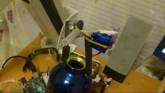
So let’s see all that in action. The following example sketch sweeps four servos across 90 degrees:

#include "Tlc5940.h"
#include "tlc_servos.h"

void setup()
{
  tlc_initServos();  // Note: this will drop the PWM freqency down to 50Hz.
}

void loop()
{
  for (int angle = 0; angle < 90; angle++) {
    tlc_setServo(0, angle);
    tlc_setServo(1, angle);
    tlc_setServo(2, angle);
    tlc_setServo(3, angle);    
    Tlc.update();
    delay(5);
  }
  for (int angle = 90; angle >= 0; angle--) {
    tlc_setServo(0, angle);
    tlc_setServo(1, angle);
    tlc_setServo(2, angle);
    tlc_setServo(3, angle);    
    Tlc.update();
    delay(5);
  }
}

And the following video captures those four servos in action:


If you servos are not rotating to the correct angle – for example you ask for 180 degrees and they only rotate to 90 or thereabouts, a little extra work is required. You need to open the tlc_servos.h file located in the TLC5940 Arduino library folder and experiment with the values for SERVO_MIN_WIDTH and SERVO_MAX_WIDTH. For example change SERVO_MIN_WIDTH from 200 to 203 and SERVO_MAX_WIDTH from 400 to 560.

Managing current and heat 

As mentioned earlier, the TLC5940 can handle a maximum of 120 mA per channel. After some experimenting you may notice that the TLC5940 does get warm – and that’s ok. However there is a maximum limit to the amount of power that can be dissipated before destroying the part. If you are just using normal garden-variety LEDs or smaller servos, power won’t be a problem. However if you’re planning on using the TLC5940 to the max – please review the notes provided by the library authors.

Conclusion

Once again you’re on your way to controlling an incredibly useful part with your Arduino. Now with some imagination you can create all sorts of visual displays or have fun with many servos. And if you enjoyed the tutorial, or want to introduce someone else to the interesting world of Arduino – check out my book (now in a third printing!) “Arduino Workshop” from No Starch Press.

In the meanwhile have fun and keep checking into tronixstuff.com. Why not follow things on twitterGoogle+, subscribe  for email updates or RSS using the links on the right-hand column? And join our friendly Google Group – dedicated to the projects and related items on this website. Sign up – it’s free, helpful to each other –  and we can all learn something.

The post Tutorial – Arduino and the TLC5940 PWM LED Driver IC appeared first on tronixstuff.

Tronixstuff 21 Oct 03:47

Harry Potter location clock spies on your smart phone

The location clock found in the Harry Potter books makes for a really fun hack. Of course there’s no magic involved, just a set of hardware to monitor your phone’s GPS and a clock face to display it.

[Alastair Barber] finished building the clock at the end of last year as a Christmas gift. The display seen above uses an old mantelpiece clock to give it a finished look. He replace the clock face with a print out of the various locations known to the system and added a servo motor to drive the single hand. His hardware choices were based on what he already had on hand and what could be acquired cheaply. The an all-in-one package combines a Raspberry Pi board with a USB broadband modem to ensure that it has a persistent network connection (we’ve seen this done using WiFi in the past). The RPi checks a cellphone’s GPS data, compares it to a list of common places, then pushes commands to the Arduino which controls the clock hand’s servo motor. It’s a roundabout way of doing things but we imagine everything will get reused when the novelty of the gift wears off.


Filed under: gps hacks

3d printed hexapod robot

This hexapod was made almost entirely via 3d printing (translated). The parts that you need to supply include a few fasteners to make connections, twelve servo motors, and a method of driving them. As you can see in the video after the break, all those parts come together into a little robot that functions quite well. The only thing that we think is missing are some grippy feet to help prevent slipping.

[Hugo] calls the project Bleuette. It is completely open source, with the cad files and source code available on his Github repository. There is additional information in the wiki page of that repo. This gives us a good look at the electronic design. He’s controlling the legs with an Arduino, but it’s all dependent on his own shield which features a PIC 18F452 to take care of the signals used to drive all of the servo motors. The board also has some peripherals to monitor the current draw and regulate the incoming power.


Filed under: robots hacks
Hack a Day 30 Jan 20:01

Arduino using a straight key for Morse code assistance

For those unfamiliar with Ham Radio, there are lots of fancy tools these days to make it easier for the radio operator. But enthusiasts still like to get back to basics, and one way to do this is to participate in Straight Key Night. This is when you pull out your traditional Morse code keyer and have a chat with others around the world. The most recent event was on New Year’s Eve. The only drag is that it sometimes takes a while to find another Ham who’s listening, and this can mean repetitively keying the letters QC SKN for long periods of time (QC invites listeners to respond, and SKN is to inform them you’re participating in Straight Key Night). Sure, a programmable keyer will do this for you, but that is against the spirit of the event. [Mike Herr] found a grey area by mechanically interfacing an Arduino with a straight key.

You can see the straight key being pressed by a hobby servo in the image above. The servo is driven by the Arduino, which will transmit the series of letters automatically. As you can see in the video after the break, once [Mike] hears back from a fellow operator he switches to a huge wooden straight key for the rest of the conversation.


Filed under: radio hacks
Hack a Day 03 Jan 22:01

Number of Servo's Attached to an Arduino.

Just a quick question that I'm struggling to get a straight answer from the intertubes about...

I'm looking at purchasing an arduino board to control some servo's, and wondering how many each can control?

For example: Uno R3 has 14 digital i/o pins (6PWM outputs), and 6 analog inputs. What does this mean exactly?

Obstacle avoidance robot (made from drift car)

Primary image

What does it do?

Navigate around via ultrasound

Hello again everybody my name is chickenparmi, and I like robots.

Today I would like to show you my obstacle avoidance bot, with a difference. The difference with this bot is that it has been build onto an RC drift car, meaning it goes very fast and is very dangerous.

Cost to build

Embedded video

Finished project

Complete

Number

Time to build

Type

URL to more information

Weight

read more

Tea-bagging an Arduino

[Dmitry Narkevich] likes a strong cup of tea and his method of getting there is to oscillate the tea bag as it steeps. But why take the time to do this when you can make an Arduino brew your tea for you. As you can see, he rigged up a system to move the tea bag as it steeps in his metal bottle.

The motion is provided by a hobby servo connected to an Arduino. This makes timing the process very simple and we’d imaging it’s only a matter of time before he adds an alarm so he’ll know when it’s ready. But the real hack comes in the apparatus that connects the servo to the bottle. Since he’ll be drinking out of it the assembly needs to be easy to remove and should be able to stand up to the abuse of being clamped on and taken off a few times each day.

The base of the device is a guitar capo. This is meant to gently clamp to the finger board of a guitar using spring tension so it is already covered in rubber which gives it a firm grip on the bottle’s opening. The servo is connected to a metal part from a stapler, and the string drapes over the body of a disposable pen. Don’t miss this in action in the clip after the break.

If you don’t have a servo on hand you could try using the sled from an optical drive.

[via Reddit]


Filed under: cooking hacks
Hack a Day 17 Dec 17:03

The A.S.R.B.

Primary image

What does it do?

Navigate via GPS, Compass, and avoids obstacles using 5 IR sensors

Hi all, I'm Matt and currently a junior in high school. I built first robot called the "A.S.R.B." over the summer for the Authentic Science Reseach Program and I wanted to share it with all of you! *I'm going to apologize in advanced if my spelling/wording/grammar is terrible--It's been a long day and I'm in a rush to get this posted.* Using the chassis of the duratrax evader EXT-2, I built this robot from the ground up.  I swapped out the esc and dc motor for a traxxas 12t 550 that I had lying around, and the esc is now the traxxas xl-5.

Cost to build

$300,00

Embedded video

Finished project

Number

Time to build

100 hours

Type

wheels

URL to more information

Weight

3500 grams

read more