Posts with «servo» label

Visualizing air quality with interactive origami flowers

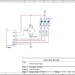
“Under the Dome – PMgami” is an installation created by designer Jiayu  Lui using Arduino Nano. Inspired by paper origami techniques, the digitally fabricated flowers move and change color according to the quality of air measured locally. The main aim of the installation is to obtain a more intuitive way to communicate pollution data and  the relationship between technology and nature.

In the gallery you can explore some other pictures and the schematic. Check the video below to see the installation in action!


New Project: Build an Automatic Photo Rig for Perfect Panoramas

Make an automatic camera rig for shooting high-resolution panoramas with a point-and-shoot camera.

Read more on MAKE

The post Build an Automatic Photo Rig for Perfect Panoramas appeared first on Make: DIY Projects, How-Tos, Electronics, Crafts and Ideas for Makers.

MT8870 DTMF - Dual Tone Multi Frequency Decoder

Project Description

We will be using an MT8870 DTMF module with an Arduino UNO to control a small servo motor in this project. The DTMF module gives the Arduino super-powers and allows you to control the Servo motor in so many ways. For example, this tutorial will show you how to control the servo motor using:
  • a YouTube Video
  • a voice recorder
  • A web application (Online tone generator)
  • A smart phone app (DTMF Pad)
  • A touch-tone phone to cell-phone call
All of these control methods will take advantage of the same exact Arduino code/sketch. But how???
The MT8870 DTMF decoder is quite a neat little module that allows you incorporate DTMF technology into your arduino projects. DTMF stands for Dual-Tone Multi-Frequency. DTMF tones are commonly associated with touch-tone phones and other telecommunication systems. When you press the number "1" on a touch-tone phone, two sine waves with frequencies: 697Hz and 1209Hz are combined to produce a unique DTMF signal which can be transmitted through the phone line. The MT8870 DTMF module can take this signal as an input, and decode it to produce a binary output.


The DTMF module does not care how you produce the DTMF tone. However, if it receives this tone, it will decode it. We can take advantage of this feature to supply the module with tones from different sources. The module has a 3.5mm port for line input. Providing you can connect your DTMF source to this line input in some way, it should work. I must warn you, however that this is a line input and NOT a microphone input. If you wanted to use a microphone, you will need to boost or amplify the signal before sending it to the DTMF module.
 
You will need the following parts for this project
 

Parts Required:

Software/Apps Required

Arduino Sketch


Upload the following sketch to the Arduino.
 

1
2
3
4
5
6
7
8
9
10
11
12
13
14
15
16
17
18
19
20
21
22
23
24
25
26
27
28
29
30
31
32
33
34
35
36
37
38
39
40
41
42
43
44
45
46
47
48
49
50
51
52
53
54
55
56
57
58
59
60
61
62
/* ================================================================================================================================================== Project: MT8870 DTMF Servo sketch Author: Scott C Created: 4th August 2015 Arduino IDE: 1.6.4 Website: http://arduinobasics.blogspot.com/p/arduino-basics-projects-page.html Description: This project will allow you to control a Servo motor using an Arduino UNO and a MT8870 DTMF Module. The DTMF signal is received through the 3.5mm port of the DTMF module and is decoded. We will use the decoded output to control the position of the Servo. A SG-5010 Servo motor was used in this project. ===================================================================================================================================================== *///This sketch uses the Servo library that comes with the Arduino IDE #include <Servo.h> //Global variables----------------------------------------------------------------------------------------- Servo SG5010; // The SG5010 variable provides Servo functionality int servoPosition = 0; // The servoPosition variable will be used to set the position of the servo byte DTMFread; // The DTMFread variable will be used to interpret the output of the DTMF module. const int STQ = 3; // Attach DTMF Module STQ Pin to Arduino Digital Pin 3 const int Q4 = 4; // Attach DTMF Module Q4 Pin to Arduino Digital Pin 4 const int Q3 = 5; // Attach DTMF Module Q3 Pin to Arduino Digital Pin 5 const int Q2 = 6; // Attach DTMF Module Q2 Pin to Arduino Digital Pin 6 const int Q1 = 7; // Attach DTMF Module Q1 Pin to Arduino Digital Pin 7 /*========================================================================================================= setup() : will setup the Servo, and prepare the Arduino to receive the MT8700 DTMF module's output. ========================================================================================================== */void setup() { SG5010.attach(9); // The Servo signal cable will be attached to Arduino Digital Pin 9 SG5010.write(servoPosition); // Set the servo position to zero. //Setup the INPUT pins on the Arduino pinMode(STQ, INPUT); pinMode(Q4, INPUT); pinMode(Q3, INPUT); pinMode(Q2, INPUT); pinMode(Q1, INPUT);} /*========================================================================================================= loop() : Arduino will interpret the DTMF module output and position the Servo accordingly ========================================================================================================== */void loop() { if(digitalRead(STQ)==HIGH){ //When a DTMF tone is detected, STQ will read HIGH for the duration of the tone. DTMFread=0; if(digitalRead(Q1)==HIGH){ //If Q1 reads HIGH, then add 1 to the DTMFread variable DTMFread=DTMFread+1; } if(digitalRead(Q2)==HIGH){ //If Q2 reads HIGH, then add 2 to the DTMFread variable DTMFread=DTMFread+2; } if(digitalRead(Q3)==HIGH){ //If Q3 reads HIGH, then add 4 to the DTMFread variable DTMFread=DTMFread+4; } if(digitalRead(Q4)==HIGH){ //If Q4 reads HIGH, then add 8 to the DTMFread variable DTMFread=DTMFread+8; } servoPosition = DTMFread * 8.5; //Set the servoPosition varaible to the combined total of all the Q1 to Q4 readings. Multiply by 8.5 to amplify the servo rotation. } SG5010.write(servoPosition); //Set the servo's position according to the "servoPosition" variable. }


Fritzing Sketch


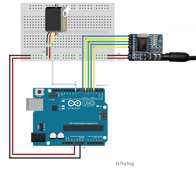
Connect the Arduino to the MT8870 DTMF module, and to a Servo.
Use the following Fritzing sketch as a guide.
 
(Click the image above to enlarge it)


Discussion


You will need to connect a cable from the DTMF module's 3.5mm port to that of your smart phone, computer, voice recorder or any other DTMF source of your choice.
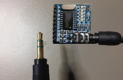


When you power up your Arduino, the Servo motor should turn all the way to the left to it's zero position. Once the DTMF module receives a DTMF signal, it will identify the relevant frequecies as described in the table at the beginning of this tutorial, and produce a binary like output. You will notice the DTMF module's onboard LEDs light up when a tone is detected. Onboard LED (D5) will turn on for the length of the DTMF tone it just received, and turn off when the tone has stopped. On the other hand, the onboard LEDs (D1 to D4) will light up depending on the tone received, and will remain lit until the module receives another tone. The onboard LEDs are a visual representation of the voltages applied to the DTMF module's pins (Q1 to Q4, and STQ). Q1 matches D1, Q2 matches D2 etc etc. and STQ matches D5.
 
You will notice that there are two STQ pins on the DTMF module. The STQ pin that is closest to Q4 will only go high when a DTMF tone is detected, and will remain high for the duration of the tone. The other STQ pin is the exact opposite. It will switch LOW when a tone is received and remain LOW for the duration of the tone. When there is no tone, this STQ pin will remain HIGH. The table below provides a summary of the DTMF module outputs, with a blue box representing a voltage applied to that pin (HIGH), whereas a black box indicates no voltage applied (LOW).


 
In order to follow this project, you need a source of DTMF tones. You can produce DTMF tones using a touch-tone phone, or through the use of a DTMF Pad app. If you are feeling creative, you can create a DTMF song/tune like the one I posted on YouTube. You can see the video below:


As you can see from the video, I also recorded the DTMF tune onto a voice recorder, and was able to control the servo that way. If you are not feeling creative, you can visit this website to create DTMF tones from your browser.

Concluding comments


This project was very fun, and shows some novel ways to control your Arduino. After completing the project, I realised that I could use this module to alert me when new emails or messages arrive on my phone or computer. If you have the ability to change the email or message notification sound to a DTMF tone, you should be able to get the module and Arduino to respond accordingly. Oh well, maybe I'll save that project for another day.
 
If this project helped you in anyway or if you use my code within your project, please let me know in the comments below. I would be interested to see what you did.


If you like this page, please do me a favour and show your appreciation :

 
Visit my ArduinoBasics Google + page.
Follow me on Twitter by looking for ScottC @ArduinoBasics.
I can also be found on Pinterest and Instagram.
Have a look at my videos on my YouTube channel.


However, if you do not have a google profile...
Feel free to share this page with your friends in any way you see fit.

Giant Fog-Breathing Robotic Crow Shoots Lasers

Artist David Cranmer's "Stakcgrox" is a 3.5 meter tall robotic crow with a rotating head and glowing eyes that shoot lasers.

Read more on MAKE

The post Giant Fog-Breathing Robotic Crow Shoots Lasers appeared first on Make: DIY Projects, How-Tos, Electronics, Crafts and Ideas for Makers.

Smile! This plant wants to take a selfie with you

Selfie Plant is an interactive installation taking pictures of itself using Arduino Yún, Facebook Graph APIs and then uploads them to Facebook. It was developed by a group of students at the Copenhagen Institute of Interaction Design during “The secret life of objects” course held also by Arduino.cc team. The final prototype was placed in the exhibition of the school, to see the interaction of the audience with it and you can see the result on Facebook.

The Selfie Plant is an attempt to provoke some thoughts above genre of expression. The Selfie Plant expresses itself in the form of nice-looking selfies, which it clicks according to its mood, weather or occasion. It mimics human behaviour, by giving it’s best pose and adjusting the camera angle to take the perfect selfie.


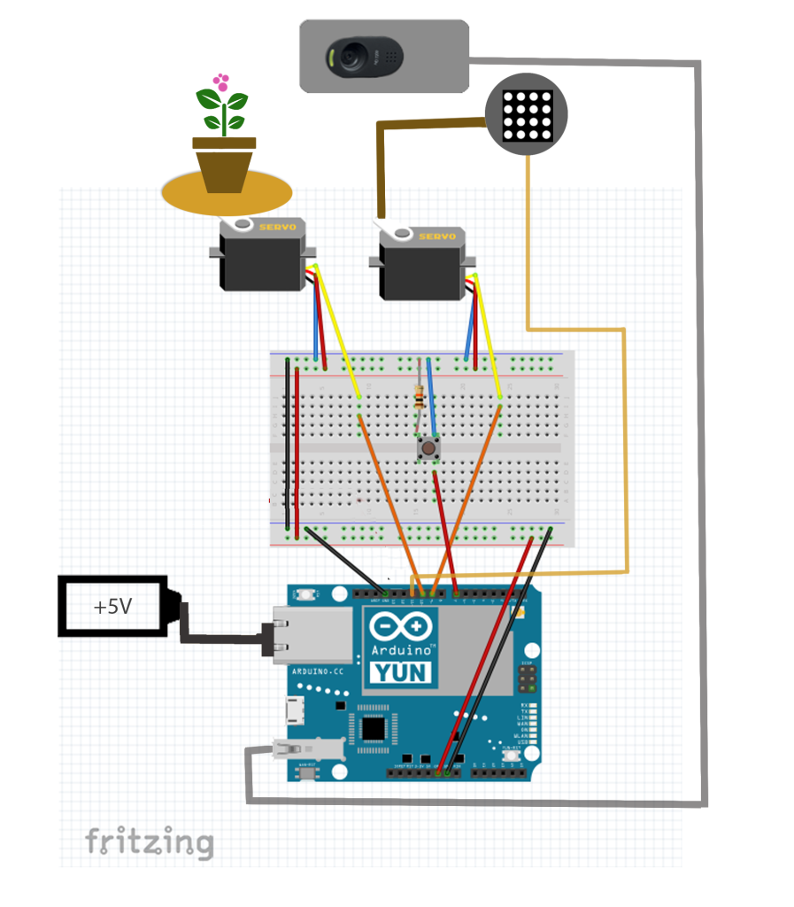
In the documentation on Github you can find all the details of the project composed by an Arduino Yún, controlling 2 servo motors and adjusting the positions of the plant and the camera stick; a python script (facebook.py) which communicates with Facebook’s graph API to post the captured photos on plant’s Facebook profile. In addition you’ll need also a LED Matrix, a Bread Board and 5 Volt Battery.

Here’s a preview of the diagram:


Smile! This plant wants to take a selfie with you

The Selfie Plant is an interactive installation taking pictures of itself using Arduino Yún, Facebook Graph APIs and then uploads them to Facebook. It was developed by a group of students at the Copenhagen Institute of Interaction Design during “The secret life of objects” course held also by Arduino.cc team by Joshua Noble and Simone Rebaudengo. The final prototype was on display at the class exhibition, to observe the interaction of the audience with it, and the results are on Facebook.

The Selfie Plant is an attempt to provoke some thoughts above genre of expression. The Selfie Plant expresses itself in the form of nice-looking selfies, which it clicks according to its mood, weather or occasion. It mimics human behaviour, by giving it’s best pose and adjusting the camera angle to take the perfect selfie.

In the documentation on Github you can find all the details of the project composed by an Arduino Yún, controlling 2 servo motors and adjusting the positions of the plant and the camera stick; a python script (facebook.py) which communicates with Facebook’s graph API to post the captured photos on plant’s Facebook profile. In addition you’ll need also a LED Matrix, a Bread Board and 5 Volt Battery.

Here’s a preview of the diagram:


The Simplest Quadrupedal Robot Ever

Wheeled and tracked robots are easy mode, and thanks to some helpful online tutorials for inverse kinematics, building quadruped, hexapod, and octopod robots is getting easier and easier. [deshipu] came up with what is probably the simplest quadruped robot ever. It’s designed to be a walking robot that’s as cheap and as simple to build as possible.

The biggest problem with walking robots is simply the frame. Where a wheeled robot is basically a model car, a walking robot needs legs, joints, and a sturdy frame to attach everything to. While there are laser cut hexapod frames out there, [deshipu]’s Tote robot uses servos for most of the skeleton. The servos are connected to each other by servo horns and screws.

The electronics are based on an Arduino Pro Mini, with a PCB for turning the Arduino’s pins into servo headers. Other than that, a 1000uF cap keeps brownouts from happening, and a 1S LiPo cell provides the power.

Electronics are easy, and the inverse kinematics and walking algorithms aren’t. For that, [deshipu] has a few tutorials for these topics. It’s a very complete guide to building a quadruped robot, but it’s still a work in progress. That’s okay, because [deshipu] says it will probably remain a work in progress until every kid on Earth builds one.


Filed under: robots hacks
Hack a Day 07 May 15:00

Making Servos Spin Right Round Without Stopping

[Brian B] found a handful of servos at his local hackerspace, and like any good hacker worth his weight in 1N4001’s, he decided to improve upon their design. Most servos are configured to spin only so far – usually 180 degrees in either direction. [Brian B’s] hack makes them spin 360 degrees in continuous rotation.

He starts off by removing the top most gear and making a small modification with a razor. Then he adds a little super glue to the potentiometer, and puts the thing back together again. A few lines of code and an arduino confirms that the hack performs flawlessly.

We’ve seen ways to modify other types of servos for 360 rotation. There’s a lot of servos out there, and every little bit of information helps. Be sure to check your parts bin for any Tower Pro SG90 9g servos and bookmark this article. It might come in handy on a rainy day.


Filed under: Arduino Hacks
Hack a Day 04 May 09:01

3D Printed Fish Feeder

[Helios Labs] recently published version two of their 3D printed fish feeder. The system is designed to feed their fish twice a day. The design consists of nine separate STL files and can be mounted to a planter hanging above a fish tank in an aquaponics system. It probably wouldn’t take much to modify the design to work with a regular fish tank, though.

The system is very simple. The unit is primarily a box, or hopper, that holds the fish food. Towards the bottom is a 3D printed auger. The auger is super glued to the gear of a servo. The 9g servo is small and comes with internal limiters that only allow it to rotate about 180 degrees. The servo must be opened up and the limiters must be removed in order to enable a full 360 degree rotation. The servo is controlled by an Arduino, which can be mounted directly to the 3D printed case. The auger is designed in such a way as to prevent the fish food from accidentally entering the electronics compartment.

You might think that this project would use a real-time clock chip, or possibly interface with a computer to keep the time. Instead, the code simply feeds the fish one time as soon as it’s plugged in. Then it uses the “delay” function in order to wait a set period of time before feeding the fish a second time. In the example code this is set to 28,800,000 milliseconds, or eight hours. After feeding the fish a second time, the delay function is called again in order to wait until the original starting time.


Filed under: 3d Printer hacks, Arduino Hacks