Posts with «sensor» label

Grove Water Sensor


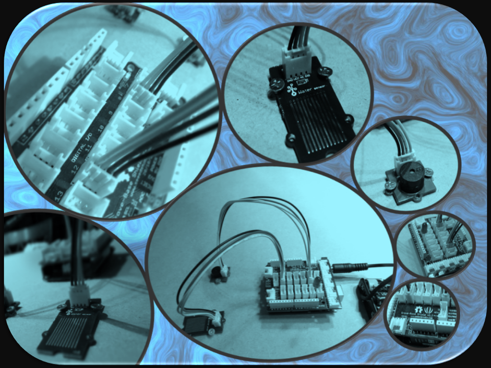
Connecting a water sensor to an Arduino is a great way to detect a leak, spill, flood, rain etc. It can be used to detect the presence, level, volume and/or the absence of water. While this could be used to remind you to water your plants, there is a better Grove sensor for that. The sensor has an array of exposed traces which will read LOW when water is detected. In this tutorial, we will connect the Water Sensor to Digital Pin 8 on the Arduino, and will enlist the very handy Grove Piezo buzzer and an LED to help identify when the Water sensor comes into contact with a source of water.


Parts Required:

Putting it together


If you have a Grove Base Shield, you just have to connect the Grove Water Sensor to D8 on the shield, and the Buzzer to D12 on the Shield. My Grove base shield obstructs the onboard LED, so I will attach an LED to Digital pin 13. If you do not have a Grove base shield, then you should connect the Sensors as described in the tables below:


Arduino Sketch


  1
2
3
4
5
6
7
8
9
10
11
12
13
14
15
16
17
18
19
20
21
22
23
24
25
26
27
28
29
30
31
32
33


/* 
  Grove Water Sensor sketch 
     Written by ScottC 5th August 2014
     Arduino IDE version 1.0.5
     Website: http://arduinobasics.blogspot.com
     Description: Use Grove Water Sensor to detect leaks, floods, spills, rain etc.
     Credits: This sketch was inspired by this website:
              http://www.seeedstudio.com/wiki/Grove_-_Water_Sensor     
 ------------------------------------------------------------- */
#define Grove_Water_Sensor 8     //Attach Water sensor to Arduino Digital Pin 8
#define Grove_Piezo_Buzzer 12    //Attach Piezo Buzzer to Arduino Digital Pin 12
#define LED 13                   //Attach an LED to Digital Pin 13 (or use onboard LED)
void setup(){
pinMode(Grove_Water_Sensor, INPUT); //The Water Sensor is an Input
pinMode(Grove_Piezo_Buzzer, OUTPUT); //The Piezo Buzzer is an Output
        pinMode(LED, OUTPUT); //The LED is an Output
}

void loop(){
        /* The water sensor will switch LOW when water is detected.
           Get the Arduino to illuminate the LED and activate the buzzer
           when water is detected, and switch both off when no water is present */
if(digitalRead(Grove_Water_Sensor) == LOW){
                digitalWrite(LED,HIGH);
digitalWrite(Grove_Piezo_Buzzer, HIGH);
                delay(2);
                digitalWrite(Grove_Piezo_Buzzer, LOW);
                delay(40);
        }else{
                digitalWrite(Grove_Piezo_Buzzer, LOW);
                digitalWrite(LED,LOW);
        }
}


The Video


If you liked this tutorial - please show your support :

ScottC 05 Aug 16:38

Add long-distance connectivity to your Arduino with the CATkit System

Introduction

Have you ever wanted to connect your Arduino to sensors or other devices but over a long distance? And we don’t mean a few metres – instead, distances of up to 100 metres? Doing so is possible with the CATkit system from SMART greenhouse.

This system is a combination of small boards that are connected between your Arduino and external devices using CAT5 networking cable, giving a very simple method of connecting devices over distances you previously thought may not have been possible – or have used costly wireless modules in the past.

The maximum distances possible depend on the signal type, for example:

  • analogue signals up to 100 metres (with a 0.125 V drop)
  • 1-wire signals (ideal for DS18B20 temperature sensors) up to 75 metres
  • SPI bus up to 50 metres
  • I2C bus up to 35 metres
  • Serial data at 9600 bps varies between 50 and 100 metres

In principle you could also use this with other development boards that utilise the Arduino Uno shield form-factor and work with 5V – so not for the Arduino Due, etc. For more information check out the .pdf documentation at the bottom of this page.

How it works

For each system you need one CATkit Arduino shield:

… and one or more Kitten boards. These are both inline – in that they can “tap in” to a run:

or have one RJ45 socket for installation at the end of a cable run:

Note that the inline Kitten has male pins for the breakout, and the end unit has females. These units are available in kit form or assembled. You then use the network cables between the shield and each Kitten, for example:

Each Kitten can distribute six signals, and up to three can be connected to one CATkit shield. These three distribute analogue pins 0~5, digital pins 0~5 and 6~11 respectively. You can also introduce external power to the CATkit shield and the onboard regulator will offer 5V at up to 950 mA for the power bus which can be accessed from the inline or end Kitten boards. This saves having to provide separate 5V power to devices away from the Arduino, and very convenient for sensors or remote I2C-interface displays.  

Using the CATkit system

If you have the units in kit form, assembly is very simple. For example – the main CATkit shield:

The shield is in the latest Arduino R3 format, and all the required parts are included. The PCB is neatly solder-masked and silk-screened so soldering is easy. The power regulator is in D-PAK form, however with a little help it’s easy to solder it in:

Otherwise the shield assembly is straight forward, and in around ten minutes you have the finished product (somehow we lost the DC socket, however one is included):

The cut-out in the PCB gives a neat clearance for the USB socket.  The inline unit was also easily assembled, and again the kit includes all the necessary parts:

… and after a few minutes of soldering the board is ready:

A benefit of using the kit version is that you can directly solder any wires from sensors straight to the PCB for more permanent installations. 

Using the CATkit system

Any Arduino user with a basic understanding of I/O will be ready for the CATkit system. You can think of it as a seamless extension to the required I/O pins, taking into account the maximum distances possible as noted on the CATkit website or earlier in this review.

For a quick test we connected an I2C-interface LCD using an inline Kitten module via 5M of network cable, as shown in this video.

Conclusion

With a little planning and the CATkit system you can create neat plug-and-play sensor or actuator networks with reusable lengths of common networking cable. To do so is simple – and it works, so for more information and distributors please visit the product website.

And if you enjoyed this article, or want to introduce someone else to the interesting world of Arduino – check out my book (now in a third printing!) “Arduino Workshop”.

Have fun and keep checking into tronixstuff.com. Why not follow things on twitterGoogle+, subscribe  for email updates or RSS using the links on the right-hand column, or join our forum – dedicated to the projects and related items on this website. Sign up – it’s free, helpful to each other –  and we can all learn something.

[Note – CATkit system parts are a promotional consideration from SMART green house]

The post Add long-distance connectivity to your Arduino with the CATkit System appeared first on tronixstuff.

Tronixstuff 12 Apr 23:33

PIR Sensor (Part 2)


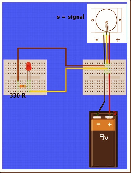
In this tutorial we will connect our HC-SR501 PIR (movement) Sensor to an Arduino UNO. The PIR sensor will be powered by the Arduino and when movement is detected, the PIR sensor will send a signal to Digital Pin 2. The Arduino will respond to this signal by illuminating the LED attached to Pin 13.

PIR Sensor (Part 1) : Showed that this sensor can be used in isolation (without an Arduino). However, I will still demonstrate how you can attach this sensor to the Arduino so that we can move forward to more advanced objectives and concepts.


Video


Parts Required


Fritzing Sketch


Arduino Sketch


 1
2
3
4
5
6
7
8
9
10
11
12
13
14
/*Simple PIR sketch: Written by ScottC, 19th Dec 2013

http://arduinobasics.blogspot.com/

----------------------------------------------------*/

void setup(){
pinMode(13,OUTPUT);
pinMode(2,INPUT);
}

void loop(){
digitalWrite(13,digitalRead(2));
}


The sketch above reads the signal coming in from the PIR sensor on Pin 2, and if it reads HIGH, it light up the LED attached to Pin 13. If it reads LOW, it will turn the LED off. This is all controlled by line 13 in the Arduino Sketch above.

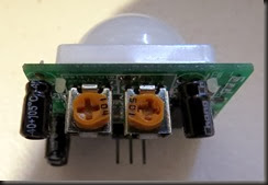
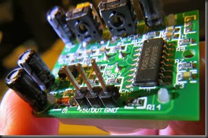
The following table helps to identify the purpose of the potentiometers on the PIR sensor. Most people say they use trial and error. I will attempt to reduce the mystery of these components on the PIR board.


104 (Left) – Max


LED on = 20 sec
LED off = 3 sec

When you move the 104 labelled potentiometer all the way to the left (max position), the LED will remain on for 20 seconds after movement is detected. The 20 seconds is independent of the other potentiometer (105) setting. When the LED turns off, it will remain off for 3 seconds before the sensor will trigger again from any further movement.


104 (Right) – Min


LED on = 1 sec
LED off = 3 sec

When you move the 104 labelled potentiometer all the way to the right (min position), the LED will remain on for 1 second after movement is detected. When the LED turns off, it will remain off for 3 seconds before the sensor will trigger again from any further movement.


105 (Left) – Max


Most sensitive – Detects movement from over 10 steps away.

The 105 labelled potentiometer controls the sensitivity of the PIR sensor. When in the left position, the PIR sensor is most sensitive and small amounts of movement will trigger the sensor. It detected my movement (ie a single step to the left of right) from over 10 steps away from the sensor. I was very impressed.


105 (Right) – Min


Least sensitive: Need significant movement for sensor to trigger. Detects movement from about 4 steps away.

When the 105 labelled potentiometer is twisted to the right, the PIR sensor becomes a lot less sensitive. I needed to take much bigger steps to the left or right to trigger the sensor (about 3 times the size compared to the left position). It also had a lot more trouble detecting movement occurring further away. It only really started to detect my movement when I was about 4 steps away from it. 

My preferred combination was 104-Right (min) + 105-Left (max), which meant that the sensor would remain on for only a short period of time, and detect any subtle movements in the room. This combination is displayed below:


I have not tested to see how it performs over a very long period with this setting, and whether it would suffer from false positive readings, but that could easily be fixed by turning the 105 labelled potentiometer a bit more to the right.

PIR Sensor (Part 1)


PIR sensors are pyroelectric or “passive” infrared sensors which can be used to detect changes in infrared radiation levels. The sensor is split in half, and any significant difference in IR levels between the two sections of the sensor will cause the signal pin to swing HIGH or LOW. Hence it can be used as a motion detector when IR levels move across and trigger the sensor (eg. human movement across a room).
The potentiometers are used to adjust the amount of time the sensor remains “on” and “off” after being triggered.  Essentially the delay between triggered events.
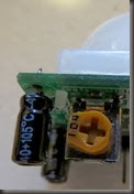
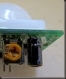
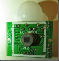
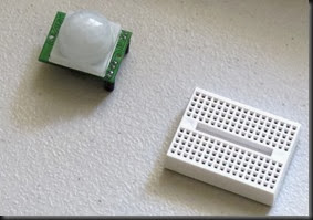
Here are a couple of pictures of the PIR sensor.


The sensor used in this tutorial is HC-SR501 PIR sensor.
You can get more information about this sensor here.


Parts Required


Sketch


Video


Sketch Explanation


The sketch described above can be used to test the functionality of the PIR sensor. I had another one of these sensors in my kit, and could not get it to work, no matter what I tried. The sensor would blink continuously even when there was no movement in the room. However, I must warn you, this specific sensor has an initialisation sequence which will cause the LED to blink once or twice in a 30-60sec timeframe. It will then remain off until the sensor detects movement. The amount of time that the LED remains on (when movement is detected) is controlled by one of the potentiometers.

Therefore, you could have it so that the LED blinks quickly or slowly after movement is detected.
If you set it to remain off for a long time, the sensor may appear to be unresponsive to subsequent movement events. Getting the timing right is mostly done out of trial an error, but at least the board indicates which side is “min” and which side is “max”.
Have a look at the PIR picture above for the potentiometer positions/timings that I used in the video.


In a future tutorial, I will connect this sensor to the Arduino. But don’t worry. The sketch is just as easy. And then the real fun begins.

See PART 2 - Connecting a PIR to an Arduino


Thankyou


I would like to thank the following people who took time out to help me when I was having issues with this sensor:
  • Steven Wallace
  • Bobby Slater
  • Pop Gheorghe
  • Mike Barela
  • Winkle ink
  • Jonathan Mayer
  • Don Rideaux-Crenshaw
  • Ralf Kramer
  • Richard Freeman
It just shows how great the maker community is. Thanks again… I almost gave up on this one !


Book – “Arduino Workshop – A Hands-On Introduction with 65 Projects”

Over the last few years I’ve been writing a few Arduino tutorials, and during this time many people have mentioned that I should write a book. And now thanks to the team from No Starch Press this recommendation has morphed into my new book – “Arduino Workshop“:

Although there are seemingly endless Arduino tutorials and articles on the Internet, Arduino Workshop offers a nicely edited and curated path for the beginner to learn from and have fun. It’s a hands-on introduction to Arduino with 65 projects – from simple LED use right through to RFID, Internet connection, working with cellular communications, and much more.

Each project is explained in detail, explaining how the hardware an Arduino code works together. The reader doesn’t need any expensive tools or workspaces, and all the parts used are available from almost any electronics retailer. Furthermore all of the projects can be finished without soldering, so it’s safe for readers of all ages.

The editing team and myself have worked hard to make the book perfect for those without any electronics or Arduino experience at all, and it makes a great gift for someone to get them started. After working through the 65 projects the reader will have gained enough knowledge and confidence to create many things – and to continue researching on their own. Or if you’ve been enjoying the results of my thousands of hours of work here at tronixstuff, you can show your appreciation by ordering a copy for yourself or as a gift

You can review the table of contents, index and download a sample chapter from the Arduino Workshop website.

Arduino Workshop is available from No Starch Press in printed or ebook (PDF, Mobi, and ePub) formats. Ebooks are also included with the printed orders so you can get started immediately.

In the meanwhile have fun and keep checking into tronixstuff.com. Why not follow things on twitterGoogle+, subscribe  for email updates or RSS using the links on the right-hand column? And join our friendly Google Group – dedicated to the projects and related items on this website. Sign up – it’s free, helpful to each other –  and we can all learn something.

The post Book – “Arduino Workshop – A Hands-On Introduction with 65 Projects” appeared first on tronixstuff.

Twine Cloud Shield puts Arduino gadgets online in seconds (video)

If you're hip-deep in Arduino projects, you're likely aware of shields: graft-on boards that add functionality, most often getting the Arduino in touch with the rest of the world. Many of these require more than a little coding skill to get the ball rolling, even in light of the Netduino, which has led Supermechanical to unveil its new Twine Cloud Shield. The board links the Arduino to a Twine WiFi sensor and gives the Arduino every internet feature the Twine can offer through just three lines of code. There's even a pair of touchpads on the shield to trigger actions through capacitive touch. Do be prepared to pony up for that ease of use when it costs $35 for the Cloud Shield alone, and $150 to bundle one with the Twine. Still, the outlay may be justified if you're more interested in quickly finishing a fun experiment than frittering your time away on the basics.

Filed under: Misc, Peripherals

Comments

Source: Supermechanical

Sonar Project Tutorial


Introduction:
This project utilises the HC-SR04 ultrasonic sensor to scan for nearby objects. You can program the Arduino to sound an alarm when the sensor detects an object within a specific vicinity. Connecting it to a computer allows data to be plotted to make a simple sonar scanner. The scanning ability is made possible through the use of a hobby servo motor SG-5010, and an Adafruit motor shield v1.0.
This project could easily be extended to provide object avoidance for any robotics project. This tutorial was designed so that you could see how the components interact, and also to see how you can use and expand the functionality of the motor shield.


Parts Required:
Freetronics Eleven or any compatible Arduino.
Adafruit motor shield v1.0
HC-SR04 Ultrasonic Sensor
MG-995  or SG-5010 Standard servo
Mini Breadboard 4.5cm x 3.5cm
Female header pins to allow easy access to the analog pins on the Motor Shield
Piezo buzzer - to sound alarm
9V Battery and Battery Clip
Wiresto connect it all together

Gauge parts:

Paper (to print the face of the gauge), and some glue to stick it to the wood.
MDF Standard panel (3mm width) - for the top and base of the gauge, and the pointer.
Galvanized bracket (25x25x40mm)
Timber screws: Hinge-long threads csk head Phillips drive (4G x 12mm)
Velcro dots - to allow temporary application of the mini-breadboard to the gauge.

The gauge was used as a customisable housing for the Arduino and related parts, and to provide some visual feedback of the servo position.


The Video:


The Arduino Sketch:


 Part of the sketch above was created using Fritzing.

The Servo motor can be connected to either of the Servo motor pins (Digital 9 or 10). In this case, the Servo is attached to digital pin 10.Make sure you read the servo motor data sheet and identify the VCC (5V), GND, and Signal connectors. Not all servos have the same colour wires. My servo motor has a white signal wire, a red VCC wire and a black GND wire.

Also when connecting your wires to the HC-SR04, pay attention to the front of the sensor. It will identify the pins for you. Make sure you have the sensor facing the correct way. In this sketch, the sensor is actually facing towards you.

In this sketch - we connect the
    Echo pin to Analog pin 0 (A0).
    Trigger pin to Analog pin 1 (A1)
    VCC to a 5V line/pin 
    and GND to a GND line/pin

Pay attention to your motor shield, I have seen some pictures on the internet where the 5V and GND are reversed.


Arduino Code:
You can download the Arduino IDE from this site.

The motor shield requires the Adafruit motor shield driver library to be installed into the Arduino IDE.

 1
2
3
4
5
6
7
8
9
10
11
12
13
14
15
16
17
18
19
20
21
22
23
24
25
26
27
28
29
30
31
32
33
34
35
36
37
38
39
40
41
42
43
44
45
46
47
48
49
50
51
52
53
54
55
56
57
58
59
60
61
62
63
64
65
66
67
68
69
70
71
72
73
74
75
76
77
78
79
80
81
82
83
84
85
86
87
88
89
90
91
92
93
94
95
96
97
98
99
100
101
102
103
104
/* ArduinoBasics: Sonar Project - Created by Scott C on 10 Jan 2013
http://arduinobasics.blogspot.com/2013/01/arduino-basics-sonar-project-tutorial.html

This project uses the Adafruit Motor shield library (copyright Adafruit Industries LLC, 2009
this code is public domain, enjoy!)

The HC-SR04 sensor uses some code from the following sources:
From Virtualmix: http://goo.gl/kJ8Gl
Modified by Winkle ink here: http://winkleink.blogspot.com.au/2012/05/arduino-hc-sr04-ultrasonic-distance.html
And modified further by ScottC here: http://arduinobasics.blogspot.com/
on 10 Nov 2012.
*/

#include <AFMotor.h>
#include <Servo.h>

// DC hobby servo
Servo servo1;

/* The servo minimum and maximum angle rotation */
static const int minAngle = 0;
static const int maxAngle = 176;
int servoAngle;
int servoPos;
int servoPin = 10;


/* Define pins for HC-SR04 ultrasonic sensor */
#define echoPin A0 // Echo Pin = Analog Pin 0
#define trigPin A1 // Trigger Pin = Analog Pin 1
#define LEDPin 13 // Onboard LED
long duration; // Duration used to calculate distance
long HR_dist=0; // Calculated Distance
int HR_angle=0; // The angle in which the servo/sensor is pointing
int HR_dir=1; // Used to change the direction of the servo/sensor
int minimumRange=5; //Minimum Sonar range
int maximumRange=200; //Maximum Sonar Range

/*--------------------SETUP()------------------------*/
void setup() {
//Begin Serial communication using a 9600 baud rate
Serial.begin (9600);

// Tell the arduino that the servo is attached to Digital pin 10.
servo1.attach(servoPin);

//Setup the trigger and Echo pins of the HC-SR04 sensor
pinMode(trigPin, OUTPUT);
pinMode(echoPin, INPUT);
pinMode(LEDPin, OUTPUT); // Use LED indicator (if required)
}

/*----------------------LOOP()--------------------------*/
void loop() {

/* check if data has been sent from the computer: */
if (Serial.available()) {

/* This expects an integer from the Serial buffer */
HR_angle = Serial.parseInt();

/* If the angle provided is 0 or greater, then move servo to that
position/angle and then get a reading from the ultrasonic sensor */
if(HR_angle>-1){
/*Make sure that the angle provided does not go beyond the capabilities
of the Servo. This can also be used to calibrate the servo angle */
servoPos = constrain(map(HR_angle, 0,180,minAngle,maxAngle),minAngle,maxAngle);
servo1.write(servoPos);

/* Call the getDistance function to take a reading from the Ultrasonic sensor */
getDistance();
}
}
}

/*--------------------getDistance() FUNCTION ---------------*/
void getDistance(){

/* The following trigPin/echoPin cycle is used to determine the
distance of the nearest object by bouncing soundwaves off of it. */
digitalWrite(trigPin, LOW);
delayMicroseconds(2);

digitalWrite(trigPin, HIGH);
delayMicroseconds(10);

digitalWrite(trigPin, LOW);
duration = pulseIn(echoPin, HIGH);

//Calculate the distance (in cm) based on the speed of sound.
HR_dist = duration/58.2;

/*Send the reading from the ultrasonic sensor to the computer */
if (HR_dist >= maximumRange || HR_dist <= minimumRange){
/* Send a 0 to computer and Turn LED ON to indicate "out of range" */
Serial.println("0");
digitalWrite(LEDPin, HIGH);
} else {
/* Send the distance to the computer using Serial protocol, and
turn LED OFF to indicate successful reading. */
Serial.println(HR_dist);
digitalWrite(LEDPin, LOW);
}
}

The code above was formatted using hilite.me

Notes:
Servo Angles: You will notice on line 22, the maximum servo angle used was 176. This value was obtained through trial and error (see below).

Calibrating the servo angles
You may need to calibrate your servo in order to move through an angle of 0 to 180 degrees without straining the motor. Go to line 21-22 and change the minAngle to 0 and the maxAngle to 180. Once you load the sketch to the Arduino/Freetronics ELEVEN, you can then open the Serial Monitor and type a value like 10 <enter>, and then keep reducing it until you get to 0. If you hear the servo motor straining, then move it back up to a safe value and change the minimum servo angle to that value. Do the same for the maximum value.

In this example, the servo's minAngle value was 0, and maxAngle value was 176 after calibration, however, as you can see from the video, the physical range of the servo turned out to be 0 to 180 degrees.


The Processing Sketch

You can download the Processing IDE from this site.

 1
2
3
4
5
6
7
8
9
10
11
12
13
14
15
16
17
18
19
20
21
22
23
24
25
26
27
28
29
30
31
32
33
34
35
36
37
38
39
40
41
42
43
44
45
46
47
48
49
50
51
52
53
54
55
56
57
58
59
60
61
62
63
64
65
66
67
68
69
70
71
72
73
74
75
76
77
78
79
80
81
82
83
84
85
86
87
88
89
90
91
92
93
94
95
96
97
98
99
100
101
102
103
104
105
106
107
108
109
110
/* Created by ScottC on 10 Jan 2013 
http://arduinobasics.blogspot.com/2013/01/arduino-basics-sonar-project-tutorial.html
*/

import processing.serial.*;

int distance;
int angle=0;
int direction=1;

int[] alphaVal = new int[100]; // used to fade the lines
int[] distance2 = new int[100]; // used to store the line lengths
int lineSize = 4; // line length multiplier (makes it longer)

String comPortString;
Serial comPort;

/*---------------------SETUP---------------------------*/
void setup( ) {
size(displayWidth,displayHeight); //allows fullscreen view
smooth();
background(0); // set the background to black

/*Open the serial port for communication with the Arduino
Make sure the COM port is correct - I am using COM port 8 */
comPort = new Serial(this, "COM8", 9600);
comPort.bufferUntil('\n'); // Trigger a SerialEvent on new line

/*Initialise the line alphaValues to 0 (ie not visible) */
for(int i=0; i<91; i++){
alphaVal[i] = 0;
}
}

/*---------------------DRAW-----------------*/
void draw( ) {
background(0); //clear the screen

/*Draw each line and dot */
for(int i=0; i<91; i++){

/*Gradually fade each line */
alphaVal[i]=alphaVal[i]-4;

/*Once it gets to 0, keep it there */
if(alphaVal[i]<0){
alphaVal[i]=0;
}

/*The colour of the line will change depending on the distance */
stroke(255,distance2[i],0,alphaVal[i]);

/* Use a line thickness of 2 (strokeweight) to draw the line that fans
out from the bottom center of the screen. */
strokeWeight(2);
line(width/2, height, (width/2)-cos(radians(i*2))*(distance2[i]*lineSize), height-sin(radians(i*2))*(distance2[i]*lineSize));

/* Draw the white dot at the end of the line which does not fade */
stroke(255);
strokeWeight(1);
ellipse((width/2)-cos(radians(i*2))*(distance2[i]*lineSize), height-sin(radians(i*2))*(distance2[i]*lineSize),5,5);
}
}

/* A mouse press starts the scan. There is no stop button */
void mousePressed(){
sendAngle();
}

/*When the computer receives a value from the Arduino, it will update the line positions */
void serialEvent(Serial cPort){
comPortString = cPort.readStringUntil('\n');
if(comPortString != null) {
comPortString=trim(comPortString);

/* Use the distance received by the Arduino to modify the lines */
distance = int(map(Integer.parseInt(comPortString),1,200,1,height));
drawSonar(angle,distance);

/* Send the next angle to be measured by the Arduino */
sendAngle();
}
}

/*---------------------------sendAngle() FUNCTION----------------*/
void sendAngle(){
//Send the angle to the Arduino. The fullstop at the end is necessary.
comPort.write(angle+".");

/*Increment the angle for the next time round. Making sure that the angle sent
does not exceed the servo limits. The "direction" variable allows the servo
to have a sweeping action.*/
angle=angle+(2*direction);
if(angle>178||angle<1){
direction=direction*-1;
}
}

/*-----------------sketchFullScreen(): Allows for FullScreen view------*/
boolean sketchFullScreen() {
return true;
}

/*----------------- drawSonar(): update the line/dot positions---------*/
void drawSonar(int sonAngle, int newDist){
alphaVal[sonAngle/2] = 180;
distance2[sonAngle/2] = newDist;
}


The Processing Output


Analog IR Temperature gauge


Introduction:
The IRTEMP module from Freetronics is an infrared remote temperature sensor that can be incorporated into your Arduino / microcontroller projects. It can scan a temperature between -33 to +220 C, and can be operated using a 3.3 to 5V power supply. It can be powered directly from the Arduino 5V pin.  This module can also provide an ambient temperature reading if required.
The Servo used in this project is a SG-5010 standard servo which will be utilised to display the temperature reading from the IRTEMP module.


Parts Required:
Freetronics Eleven or any compatible Arduino.
Freetronics IRTEMP module
MG-995  or SG-5010 Standard servo
Mini Breadboard 4.5cm x 3.5cm
Protoshieldand female header pins (not essential - but makes it more tidy)
9V Battery and Battery Clip
Wiresto connect it all together

Gauge parts:
Paper (to print the face of the gauge), and some glue to stick it to the wood.
MDF Standard panel (3mm width) - for the top and base of the gauge.
Galvanized bracket (25x25x40mm)
Timber screws: Hinge-long threads csk head Phillips drive (4G x 12mm)


The Video:


The Arduino Sketch:


     The above sketch was created using Fritzing.


Arduino Code:
You can download the Arduino IDE from this site.

The IRTemp gauge requires a driver library to be installed into the Arduino IDE.
The latest IRTemp driver library can be found here.

 1
2
3
4
5
6
7
8
9
10
11
12
13
14
15
16
17
18
19
20
21
22
23
24
25
26
27
28
29
30
31
32
33
34
35
36
37
38
39
40
41
42
43
44
45
46
47
48
49
50
51
52
53
54
55
56
57
58
59
60
61
62
63
64
65
66
67
68
69
70
71
72
73
74
75
76
77
78
79
80
81
82
83
84
/* -------------------------------------------------------
Analog IR Temperature Gauge: written by ScottC on 1st Dec 2012.
http://arduinobasics.blogspot.com/2012/12/arduino-basics-analog-ir-temperature.html


* Some of the code was adapted from a sketch by Andy Gelme (@geekscape)
* For more information on using the IRTEMP
see www.freetronics.com/irtemp

* IRTemp library uses an Arduino interrupt:
* If PIN_CLOCK = 2, then Arduino interrupt 0 is used
* If PIN_CLOCK = 3, then Arduino interrupt 1 is used
---------------------------------------------------------*/

#include "IRTemp.h"
#include <Servo.h>

Servo servo1;
static const byte PIN_DATA = 2;
static const byte PIN_CLOCK = 3; // Must be either pin 2 or pin 3
static const byte PIN_ACQUIRE = 4;

static const bool SCALE=false; // Celcius: false, Farenheit: true

/* Used to capture the temperature from the IRTEMP sensor */
float irTemperature;
int temp;

/* The minimum and maximum temperatures on the gauge. */
static const int minTemp = -45;
static const int maxTemp = 135;


/* The servo minimum and maximum angle rotation */
static const int minAngle = 0;
static const int maxAngle = 175;
int servoPos;

IRTemp irTemp(PIN_ACQUIRE, PIN_CLOCK, PIN_DATA);


/*----------------------SETUP----------------------*/

void setup(void) {

servo1.attach(9); // turn on servo
}


/*-----------------------LOOP-----------------------*/

void loop(void) {
irTemperature = irTemp.getIRTemperature(SCALE);
printTemperature("IR", irTemperature);

/* If you want the ambient temperature instead - then use the code below. */
//float ambientTemperature = irTemp.getAmbientTemperature(SCALE);
//printTemperature("Ambient", ambientTemperature);

}

/*-----------printTemperature function---------------*/

void printTemperature(char *type, float temperature) {

temp=(int) temperature;
servoPos = constrain(map(temp, minTemp,maxTemp,minAngle,maxAngle),minAngle,maxAngle);

if (isnan(temperature)) {
//is not a number, do nothing
}
else {

/* To test the minimum angle insert the code below */
//servoPos = minAngle;

/*To test the maximum angle, insert the code below */
//servoPos = maxAngle;

/* Rotate servo to the designated position */
servo1.write(servoPos);
}
}

The code above was formatted using hilite.me

Notes:
Ambient temperature: If you want to get the ambient temperature from the IRTEMP module, then have a look at lines 58-59.
Servo Angles: You will notice on line 36, the maximum servo angle used was 175. This value was obtained through trial and error (see below).

Calibrating the servo angles
You may need to calibrate your servo in order to move through an angle of 0 to 180 degrees without straining the motor.Change the minAngle on line 35to a safe value (for example: 10), and the maxAngle on line 36 to a value like 170. Remove the comment tag (//) on line 76, and then run the sketch. Lower the minAngle until it reaches the minimum value on the gauge, making sure that the servo doesn't sound like it is straining to keep it in position.

Add the comment tag (//) back in, and then take out the comment tag for line 79. And follow a similar process, until you reach the maximum value on the gauge. Once again, make sure that the servo is not making a straining noise to hold it at that value. Make sure to add the comment tag back in, when you have finished the calibration.

In this example, the servo's minAngle value was 0, and maxAngle value was 175 after calibration, however, as you can see from the video, the physical range of the servo turned out to be 0 to 180 degrees.


The Temperature Gauge Picture

The following gauge was created in Microsoft Excel using an X-Y chart.  Data labels were manually repositioned in order to get the desired numerical effect.


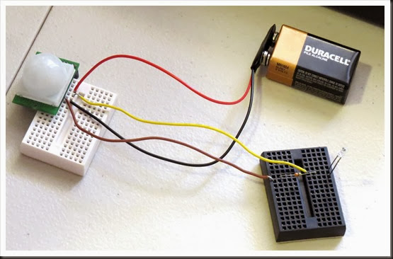
Build a Basic Infrared Motion Alarm with Weekend Projects

Build a motion-sensing alarm by combining a few common components: an Arduino, a PIR sensor, a piezo buzzer, and a breadboard. All you need is some jumper wire to connect them all, and the software to run it.

Read the full article on MAKE

Small Quadruped Robot

Primary image

What does it do?

Navigate around via ultrasound

Hi, I'm new to LMR as a member. But I've been browsing around LMR to learn robotics. First, sorry for my bad English. I finished making my quadruped robot a couple weeks ago. It was my first robotic project using microcontroller. In fact, it was my first microcontroller project. Unfortunately it wasn't well documented during the making process since I didn't plan to publish it before. :( So here is what I can collect from scattered file in my PC..


Cost to build

$150,00

Embedded video

Finished project

Complete

Number

Time to build

Type

URL to more information

Weight

read more