Posts with «robotics» label

Magnetometer and accelerometer read simultaneously

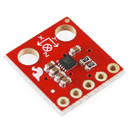
In Learning to Use I2C and Magnetometer not fried, I talked about interfacing the MAG3110 magnetometer and MQA8452Q accelerometer to an Arduino.  For both, I’m using breakout boards from Sparkfun Electronics.

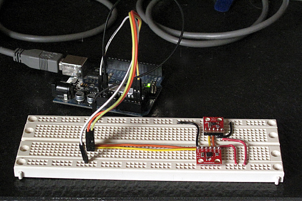
I  checked today that there are no problems when I connect both devices to the same I2C bus.

The first test was very simple: I put both the breakout boards into a breadboard and wired them together, then tried running each of the programs I’d written for the chips separately. Result: no problems—worked first time.

I then tried merging the programs (cleaning up any naming conflicts) so that both could be run from the same code.  After a few typo fixes, this also worked fine

I think I’m now ready to hand over the software to the students to use for their robot.

I still need to put the i2c.h, i2c.cpp, and accel_magnet code in some public place for others to use (perhaps on github? maybe on my web pages at work?) [UPDATE 2012-jan-31: I have put the libraries and the sample code for the accelerometer and magnetometer at http://users.soe.ucsc.edu/~karplus/Arduino/]

One thing that is still missing is doing tilt correction for the compass heading.  Since the ROV is not expected to remain level (the accelerometer is intended to be used in a feedback loop to adjust the pitch, with anything from -90° to +90° being reasonable), getting a good compass heading requires rotating the magnetometer readings into the horizontal plane.  Only one of the students in the robotics club has had trigonometry or matrix math, so I’ll have to work with him to get him to figure out how to do the tilt correction. It may be simplest conceptually  to compute pitch and roll angles first, then rotate twice, rather than trying to do the whole tilt correction in one step (especially since the Arduino does not have matrix libraries).

Related articles

Tagged: accelerometer, Arduino, I²C, magnetometer, robotics, SparkFun, SparkFun Electronics

Magnetometer was not fried

MAG3110 breakout board by Sparkfun

In Learning to Use I2C, I talked about the difficulty I’d been having getting the MAG3110 breakout board from Sparkfun to work, and my fears that I had burned it out by running it overnight at 5v (instead of the rated 3v).  I suspected that my problem was really a software problem, but debugging the software when I was afraid that the hardware was fried seemed like an exercise in futility.

I bought another of the breakout boards from Sparkfun (they’re only $15), and soldered on a header yesterday.  The code failed in almost exactly the same way with the new (presumed good) part as with the old (presumed fried) part, so I was convinced that the problem was indeed in the software.

I spent half of yesterday and most of this morning carefully rewriting the library of I2C interface code.  I was starting with example code from Sparkfun for the MMA8452Q accelerometer, which I had generalized to handle other I2C devices.

The library worked fine with the accelerometer, so I thought it was ok, but it did not work with the magnetometer. I added a lot of error checking (making sure that the microprocessor was in the expected state after each I2C operation), and found that things were not working as expected. The extra error checking made it much easier to diagnose the problems. I had to re-read the I2C documentation in the ATMega328 datasheet several times, to make sure that I had all the details right (I didn’t, of course). The documentation in that data sheet is better than several of the tutorials I’ve seen on line, and is both thorough and comprehensible in describing the interface.

I did not implement all features of the I2C  interface—in fact, I have a rather minimal implementation that uses polling rather than interrupts and assumes that the Arduino will always be the bus master.  Those assumptions are fine for most Arduino projects, which just use the I2C bus for talking to a handful of peripherals, but sometime in the future I may need to make a more complete set of code that can handle multiple masters, the Arduino as a slave device, and interrupts rather than polling and waiting for operations to finish.

Because I was more interested in simplicity and robustness than speed, I rewrote the code so that transactions were finished (and appropriate status checked) before functions returned.  With these changes I found that the STOP condition was not happening, despite being requested.  All other operations on the bus are checked with the TWINT bit  of the TWCR register and the upper bits of the TWSR register, but determining that STOP has completed requires checking the TSWTO bit of the TWCR register. The code I had started from just checked the TWINT bit for the other operations, and had a fixed timeout that was too short—it did no checking at all on the STOP state, just adding a fixed delay.

Once I got the STOP timing cleaned up (and earlier, making sure to send NAK when reading the last byte), everything worked fine.  The accelerometer code  had probably worked ok because there were enough delays after stops that the stops completed, even though I had not checked to make sure.  With the fixed code, even the magnetometer that I thought I had fried seems to work ok.

The interface for the students in the Robotics Club is fairly simple (much simpler than the standard “Wire” library):

// Read one register
uint8_t i2cReadRegister(uint8_t i2c_7bit_address, uint8_t address);
// Read num_to_read registers starting at address
void i2cReadRegisters(uint8_t i2c_7bit_address, uint8_t address, uint8_t num_to_read, uint8_t * dest);

// Write one register
void i2cWriteRegister(uint8_t i2c_7bit_address, uint8_t address, uint8_t data);
// Write num_to_write registers, starting at address
void i2cWriteRegisters(uint8_t i2c_7bit_address, uint8_t address, uint8_t num_to_write, const uint8_t *data);

I suppose I should check that there are no problems when I connect both devices to the same I2C bus, before handing this over to the students to use for their robot.

I should also put the i2c.h and i2c.cpp in some public place for others to use (perhaps on github? maybe on my web pages at work?). It is really a shame that WordPress.com does not permit code-like files as pages.

Related articles

Tagged: accelerometer, Arduino, i2c, magnetometer, robotics, SparkFun, SparkFun Electronics

Learning to use I2C

For the Santa Cruz Robotics Club, I’ve bought three sensors for their underwater ROV: a magnetometer, an accelerometer, and a pressure sensor.

Originally, we were going to an ADXL335 accelerometer (with a breakout board by Adafruit Industries) and an MPXHZ6250A pressure sensor (no magnetometer), for which I designed a small PC board, but once the specs for this year’s mission came out, we saw that they wanted us to determine compass headings for a “sunken ship”, so it seemed a natural thing to add a magnetometer to the hardware.  After looking at what was available, I chose the MAG3110 breakout board from Sparkfun, because it provided a triple-axis magnetometer for only $15.

The MAG3110 is an I2C interface, which means we need only 2 wires to hook it up (and the wires can be shared with other I2C devices).  If we are going to all the trouble of figuring out an I2C interface, I figured we might as well use it for the accelerometer as well, so I got a MMA8452Q breakout board from Sparkfun also.

I decided to do a simple test program for the I2C parts before handing them over to the robotics club, so that they could be sure they had working parts.  It was a good thing I did, because I spent more than an entire day trying to get the parts to work.  I finally gave up on the “Wire” library from the Arduino website, and tried using the i2c.h file from Sparkfun (example code linked to from the accelerometer web page).  I got that working and rewrote the library as a proper .h and .cpp file, so that it could be installed as a normal Arduino library, adding some of the utility calls that had been buried in the MMA8452 demo code.

The MMA8452Q code was working fine, so I tried using the same i2c library for the MAG3110 magnetometer.

I had gotten MAG3110 working with the Wire library, but running at 5v (I’d not noticed that it was a 3.3v part—rather, I thought I’d checked that it was a 5v part, but I was wrong).  I’d left it powered at 5v all night, and I think I burned it out, as it was quite warm in the morning.  Today, I can read and write the registers of the MAG3110, but the xyz values are not coming out reasonable at all—I frequently get the same values (like 0xF9F9)and 0x1DF9), independent of the orientation. If I read all the registers, a lot of them come out as 0xF9 or 0x1D.  Even the WHO_AM_I register (which should be 0xC4) often comes out 0x1D.  I seem to get intermittent correct values for registers, but mostly bogus values.

I’ll feel stupid if I order another part and it turns out to be a software bug, but I’m pretty sure the chip is fried.  But I guess it is time to do another Sparkfun order. (I owe them some business, after calling them for the replacement photointerrupter.)

Incidentally, I tried finding a usable pressure sensor with an I2C interface, but it doesn’t look like anyone is making them except for barometric pressure ranges for dry gases.  I suppose Freescale will eventually come out with a full range of I2C pressure sensors, but my guess is that will be a long time coming, as the automotive and industrial applications have a pretty long product design cycle (unlike consumer electronics, which is driving the barometric pressure sensors).


Tagged: accelerometer, Adafruit Industries, Arduino, magnetometer, robotics, SparkFun, SparkFun Electronics

Insert Coin: A look back at ten top projects from 2011

2011 has been a tremendous year for tech -- Amazon launched a $200 Android tablet, AT&T and Verizon continued their LTE expansion, Apple killed off the Mac mini's SuperDrive and Samsung introduced a well-received killer 5.3-inch smartphone. But tiny tech startups made their mark as well, proving that you don't need an enormous R&D budget to spur innovation. Still, development isn't free, and unless your social circle includes eager investors, seed money has been traditionally hard to come by.

For many of this year's indie devs, crowdfunding sites have been the answer, with Kickstarter leading the pack. We've seen an enormous variety of projects -- including a deluge of duds and plenty more semi-redundant iPhone accessories -- but a few treasures soared above the swill to be featured in our Insert Coin series, with many of those meeting their funding goals and even making their way into the hands of consumers. Now, as 2011 draws to a close, we've gone through this past year's projects to single out our top ten, and they're waiting for your consideration just past the break.

Continue reading Insert Coin: A look back at ten top projects from 2011

Insert Coin: A look back at ten top projects from 2011 originally appeared on Engadget on Sat, 31 Dec 2011 16:00:00 EST. Please see our terms for use of feeds.

Permalink | Email this | Comments

Underwater ROV again this year

Last year I blogged about MATE ‘s Monterey Bay Regional underwater ROV competition in Underwater ROV contest.  I coached a robotics club at my son’s high school, and they built a small vehicle which they barely got into the water the day before the contest, because we started so late.

Although my son is being home-schooled this year, we have kept the team going, losing one member and picking up another (so we still have only 3).  The robotics club is no longer affiliated with a school, but that makes no difference, as all the school provided us was an inconvenient time to meet (lunch on Tuesdays) and 15 minutes in the pool once.  We meet for 3 hours on Sundays at my house, which gives them enough time to get something done.

I’m still paying the expenses out of my own pocket, and we now have the construction of the vehicle taking up about a third of our living room (the benchtop drill press is the first thing you see on entering the house, unless it is on the floor to make room on the robotics table for the scroll saw).

The students have made considerable progress since last year, having replaced the high-resistance tether and switch box with a low-resistance power wire and a dry box that will house an Arduino microprocessor with H-bridge chips.  They’ve made the tether with a waterproof disconnect and have tested everything for water tightness (though only at bathtub depth, not 10 feet deep).  I think that they’ll have the basic vehicle and electronics finished by the end of January, leaving some time for designing and building mission-specific tools, programming the Arduino and the laptop GUI, and learning to pilot the vehicle.  Now we just have to find a pool to practice in.

The club members have gotten much more independent this year, so my coaching involves my making some suggestions about what they should work on at the beginning of the meeting, checking to see how they are doing about once an hour, and having a discussion with them about what they’ll need to design or build next over snacks near the end of the meeting.  I also try to get them to give me specific parts to buy, but I usually end up having to find and select parts for them.  If the group were bigger (and my wallet more able to tolerate mistakes), I could have the students doing more of the purchasing.

The challenges for this year have been published, and they are in the usual verbose style.  I may have a hard time getting all the students to read the specs carefully, since the specs go on and on with irrelevant “color” hiding the nuggets of critical information.  I’m not looking forward to making the items needed for practicing the missions this year, since they are described in the same wordy way as last year (which I found difficult to follow in several places), and they haven’t even released photos or drawings of what the objects are supposed to look like.  Trying to re-create the objects from the turgid assembly directions without pictures is going to be a nightmare.

The contest does not have any tasks this year that need a depth gauge (but I bought a pressure sensor, so the students will measure depth!), but they will need to determine compass headings, so we’re trying to decide whether to get a cheap compass and put it in the camera view, or add an electronic compass module to the electronics in the dry box.  An electronic compass is definitely cooler, but we may be running out of pins on the Arduino.

Related Articles

Tagged: Arduino, contests, electronic compass, H-bridge, remotely operated underwater vehicle, robotics, ROV

Boards arrived

The hexmotor rev 1.3 boards before cutting them apart.

The printed circuit boards for hexmotor rev1.3 came today from 4pcb.com. I ordered the boards on July 21, so the total turnaround time from order to delivery was only 12 days. No wonder the company is so popular for student projects—low prices and fast service will do that!

The boards looked pretty good, so the first thing I did was to check some crucial dimensions:

  • I put headers into the holes for the connection to the Arduino board and checked that it would plug in.  No problem!
  • I checked that I could spread the pins of the TLE-5206-2S chips to fit the holes where they were supposed to plug in.  No problem!  In fact, it was surprisingly easy to get the right spacing, by using the board itself as a tool for bending the pins.
  • I checked that I could put in both the MTR2 TLE-5206-2 chip and capacitor C5 without conflict (as I’d noticed that the silk screen outlines overlapped only after I’d sent in the order).  This also turned out not to be a problem
  • I checked that the mounting holes on the board lined up with those on the Arduino.  Only 2 out of 3 do.  What is going on???I got the hole placement from the Adafruit library for Eagle, and it has 3 holes, but they are not in the same places as the Arduino board.  It turns out that two of the holes correspond to holes on the Arduino board, and two to holes on the Arduino Mega board, which has holes in different locations.  Neither pair corresponds to the holes on the  Adafruit motor shield, which has only 2 diagonally opposite holes, the two holes that are actually in common between the Arduino and the Arduino Mega footprints.  For the next revision of the boards, I have to decide whether to use the 3-hole design of this board, or to go with the pair of diagonally opposite holes.  Or put in 4 holes, so that either Arduino or Arduino Mega can be securely attached with 3 screws. I think that there is room for the fourth hole, if I move one of the electrolytic capacitors.
  • I also did some continuity checks on the power lines.  The power and ground lines connect to the right pins on the TLE-5206-2 footprints, and they aren’t shorted.  The 6.25v and 5v lines also seem fine.
  • I had to make some Eagle library components for the screw terminal blocks I was using, and they seem to be fine, except for two little problems: I put a silkscreen mark for the bump on the side of the 5mm block on the wrong side, and the holes specified by the manufacturer seem a bit too big for the pins.  I’ll specify a smaller drill hole (closer to the spec for the pin size) in the next revision.  Neither of these little problems will interfere with functionality.
  • I checked out the Sparkfun header pattern, with the slightly staggered holes to hold the headers while soldering.  The holes must be a bit bigger than Sparkfun gets from their manufacturer, or my headers smaller, because the headers were not held by the staggered holes.  They fit fine, but the holes are loose enough that they aren’t held.

Tonight, I’ll fix up my Eagle library to have a 4-hole Arduino template and to have a better 5mm screw terminal component.

Here's a 12" board shear that costs $379 from Circuit Specialists.

Tomorrow I’ll go up to campus and see if I can cut the boards apart with the board shears.

I took a look at  printed circuit board shears on the web (you need to include “printed circuit” if you search, or you get book-binding equipment), and they range in price from $125 to $500, depending on size and quality.  I don’t plan to buy one for myself, but it seems like the sort of low-price, special-purpose tool that a place like Makers Factory ought to get.


Tagged: Adafruit Industries, Arduino, board shears, motor controller, Printed circuit board, robotics

Time to start doing software

The PC board for the hexmotor H-bridge is ordered and supposedly going to arrive soon, and I’ve ordered all the components from Digi-Key. The total coast of the project is looking like about $180 (including the PC board and shipping) for 2 fully populated boards (not counting an enormous amount of my time). I’ve already started designing a revised board (rev 2.0) that will be designed around the TLE-5206-2 from the beginning, and will have more versatility. I’m thinking that I’ll populate one rev 1.3 board for testing, finalize the rev 2.0 design, and send it out for fab, rather than populating a second rev 1.3 board.

Here is a preview of what my panel of 4 boards should look like.

In addition to the 6 TLE-5206-2 H-bridges, both boards have 74HC594 serial-to-parallel converters for control signals and 74HC86 XOR gates. The serial-to-parallel conversion is similar to that of the Adafruit Industries motor shield (which I have, but which does not have enough current capacity as it uses L293D H-bridges, which only support 0.6A per channel, and I need at least 2.5A per channel).

Copying the choices on the Adafruit board, I made the pin mapping LATCH=Arduino pin 12, DATA=Arduino pin 8, CLOCK=Arduino pin 4. I was wondering at first why they did not use the built-in SPI interface (which would simplify the programming of the serial output), but then realized that the output bit of the SPI interface (MOSI=pin 11) is also OC2A, one of the PWM outputs. Since there are only 6 PWM outputs (one per motor), and the serial interface does not need to be very fast, using software control of other pins is a good idea.

I’ve also brought out all the PWM signals to 3-wire servo connections, so that I can use each PWM signal as either a servo control or a motor speed control. All the connections to the Arduino digital pins are jumpered, so I can reconfigure the board if needed. For example, if I just want forward/backward/brake control of a motor, without speed control, I can rewire the input that would normally be to a PWM bit to be to a different digital pin, and free up that PWM bit for servo control.

On the hexmotor rev 2.0 board I added another 74HC594 chip (in series) so that I have 16 control bits available. Six of them are used for motor control, as on the rev 1.3 board. Another 6 are brought out to header pins adjacent to the speed control pins, so that those pins can be jumpered either to the Arduino PWM pins or to the shift register outputs, allowing 6 motors and 6 servos to be controlled by the board, as long as only 6 continuous values are needed, and the servos don’t exceed the 1.5A capacity of the switching regulator. The remaining 4 of the 16 parallel bits of the rev 2.0 will be brought out to individual header pins, so that they can be used as arbitrary digital outputs. (Also, the hexmotor 2.0 board will have an LED to indicate that 5v power is properly being provided—if the board is used as intended, with the Arduino powered from the switching regulator on the hexmotor board, this tests that all the power connections are made and the Arduino board plugged in.

I will have to start writing software for the hexmotor board soon. I’ll probably base some of the software on the Adafruit AFMotor package, to make it easier for the robotics club to switch between the Adafruit motor shield and the hexmotor board, but there will be some important differences. Since the hexmotor board has several jumpers that can customize it, but no way for the Arduino to read that configuration, I need an easy way to tell the software how the board is configured. I want software that will work with either revision of the hexmotor board. Since the rev 2.0 board has more possibilities for configuration than the rev 1.3 board (thanks to the 8 extra output bits), I’ll design the software for that, making sure that the rev 1.3 board is covered as a special case.

I’m going to have to dive into both the ATMega328 data sheet and the Arduino code to find out how to get access to all 6 PWM signals.  I already know that the Arduino initialization messes with the PWM frequencies, so the AFMotor.h control for the PWM frequencies doesn’t work.  It may turn out that using OC1A and OC2A (which the Adafruit board does not use, but which I use for motors 4 and 5) interacts in some unpleasant way with other Arduino functions.  I may have to put up with some constraints on PWM frequency, as I want to retain clock and analog input capabilities.


Filed under: Hexmotor H-bridge board, Printed Circuit Boards, Robotics Tagged: Adafruit Industries, Arduino, board shears, motor controller, Printed circuit board, robotics

Possibly salvage the boards

My son and I were looking together about whether we could salvage the board design by using the TLE-5206-2 parts that are available.

The pinout is identical, but the functionality is different.

In1 In2 5205 out1/out2 5206 out1/out2
0 0 1/0 0/0
0 1 0/1 0/1
1 0 0/0 1/0
1 1 Z/Z 1/1

The arrangements of signals that I have available to jumper to were S, PWM, and S+PWM.  The easy jumper arrangements I had were (IN1=S, IN2=PWM) and (IN1=PWM, IN2=S+PWM), which with the TLE-5205 were supposed to give me lock anti-phase drive and sign-magnitude drive.

With the 5206, lock anti-phase would require (IN1=PWM, IN2=not PWM), which I don’t have available, but the jumper setting (IN1=S, IN2=PWM) now almost makes sense as active collapse (run/brake) mode (except that it is not quite sign magnitude, since the interpretation of the pulse width is flipped depending which way the motor is supposed to turn).  The other jumper setting makes no sense.

So now I have choice:

  1. Populate a board with TLE-5206 chips and have only the run/brake mode (I could solder in jumpers, since there are no choices).  I could also omit the now-useless OR gates.
  2. Design a new board with the TLE-5206 chips in mind, with jumpering between two modes:
    • (IN1=S, IN2=S xor PWM)   run/brake with consistent magnitude interpretation
    • (IN1=PWM, IN2=S xor PWM)  lock anti-phase if S=1, brake if S=0

Wait a second!  I don’t need a new board for that! If I replace the 74HC32 quad nor-gate with a 74HC86 quad Xor, then the 5-pin headers will be

S IN1 PWM IN2 S xor PWM

I can solder the IN2 pin to S xor PWM, and just have a 3-pin header to connect IN1 to either S (for run/brake) or PWM (for lock anti-phase). The labeling on the silk screen will be wrong, but the board will be fully usable!

The interpretation of the pulse width modulation if  IN1 is set to PWM is that 0 means always on and 255 means always braking, which is kind of weird, but easily compensated for in the software. S determines the direction the motor turns.

If IN1 is set to S, then S is interpreted as RUN if it is high, STOP if it is low, and PWM gives the direction and magnitude when running (with 0 being full on in one direction and 255 being full on in the opposite direction).  PWM should probably be set to constant 0 when braking.

I think the board can be saved, and still have all the functions we needed, though we switched from sign-magnitude to active collapse as one of the modes.  The next revision of the board (if I need to make more) would fix the silk screen and replace the 5-pin header with a 3-pin header for each chip.


Filed under: Hexmotor H-bridge board, Printed Circuit Boards, Uncategorized Tagged: Arduino, design errors, motor controller, Printed circuit board, robotics

H-bridge not available

I’ll be getting a decorative but useless PC board next week.  It is a good thing it only cost me $50.

It turns out that the H-bridge that was recommended to me, Infineon’s TLE-5205, is made of unobtanium.  I thought I had checked Digi-Key’s stock before starting my design, but I must have mistyped the part number, as Digi-Key customer service just called me to say that they haven’t had any since Sept 2010 and don’t expect any in the next 18 weeks.  They do have a few  TLE-5206-2 still in stock, probably because it is a less useful part, not having the Hi-Z output state. I must have checked that part instead of the TLE-5205-2.  Probably no other distributor has any TLE-5205-2′s either, if Infineon has been unable to make any since last September.

I didn’t know that Digi-Key had customer service reps working at 8p.m. on a Saturday night—it is good to know that a supplier cares enough to keep engineer hours.

In any event, I’m going to have to completely redesign the board. The TLE-5205 is unavailable even in the surface mount packages, so I can’t just change packages.  I’ll have to find and use a different H-bridge, which will be a major pain, as the TLE-5205 came close to being ideal for this application. I suspect that since the 5206 is still available, that the problem might be with the freewheeling diodes.  Since the 5206 always has either the high-side or low-side on, it doesn’t need Schottky freewheeling diodes.  Unfortunately, most of the other H-bridges I’ve looked at expect external diodes—the TLE-5205 was attractive because it had built-in diodes, saving a lot of board space.


Filed under: Hexmotor H-bridge board, Printed Circuit Boards Tagged: Arduino, design errors, motor controller, Printed circuit board, robotics

Board panelized and ordered

I used Gerbmerge today to make a larger board out of four of my little boards, since 4 of the maximum-size Eagle freeware boards (8cm × 10cm) will fit in the 60 sq-in area limit of the $33 board from 4pcb.com’s student program.

Here is a preview of what my panel of 4 boards should look like.

It turned out to be much more difficult than I expect to install Gerbmerge.

First I had to install the SimpleParse package for Python.  That was straightforward, once I realized that the big “Looking for the latest version? Download SimpleParse-2.0.0.zip (301.5 KB) ” button on http://sourceforge.net/projects/simpleparse/files/ actually downloaded an old version, and you had to click through the directories to find version 2.1.1.a2, which was needed to get the sublibraries.  Running setup.py from the downloaded directory installed SimpleParse correctly.

Then I downloaded the gerbmerge-1.8 directory and tried installing it.  That was not so much fun, as the setup.py file was badly written.

  • First, I had to edit it to remove the MS-DOS extraneous carriage returns, which Python 2.7 does not seem to like on a Mac—that is no big deal.
  • Second, it failed because it was looking for distutils.sysconfig.get_config_var('LIBPYTHON'), which is a configuration variable that does not exist on my system.  I eventually figured out that what it should have been doing there is distutils.sysconfig.get_python_lib() and got setup.py to run.
  • Third, I still could not get gerbmerge to run, because setup.py put it in the wrong place.  I had to edit 
    fid.write(
    r"""#!/bin/sh
    python %s/site-packages/gerbmerge/gerbmerge.py $*
    """ % DestLib)

    to   
    fid.write(
    r"""#!/bin/sh
    python %s/gerbmerge.py $*
    """ % DestDir)

    and remove os.path.walk(os.path.join(DestLib, 'site-packages/gerbmerge'), fixperms, 1)

After all that fussing, I finally got Gerbmerge to run without crashing.  I then had to put together a configuration file to explain how I wanted the panelization job done.  The configuration file is not intuitive, but it is well-documented with an excellent sample to modify.

The statistics reported by Gerbmerge did alert me to one minor problem: the vias used by the auto-router used a different size hole from the ones I had placed by hand.  I figured out how to change the auto-router via size (it grabs the smallest legal size from the design-rule checker), ripped up the auto-routed stuff, and rerouted it.  That introduced some design rule violations, where newly placed vias were overlapped by some of the silkscreen, but I fixed that my manually moving the offending vias and rerouting to them.

I checked the combined board both with FreeDFM from 4pcb.com and BatchPCB, and both accepted it with no complaints.  BatchPCB charges by the square inch, so it would cost $138.57 for the 4-up board from them, more than the $124 for the boards already properly cut apart.

I ordered one of the 4-up boards from 4pcb.com for $33 plus shipping, for a total of about $50.  I only found out afterwards that they have a $50 surcharge if you have multiple copies of the same design on the board.  I hope that they don’t charge me that surcharge!  If they ask, I’ll cancel the order and redo with 4 slightly different designs (maybe customizing the silkscreen for the robotics club).

In fact, I just realized that I could probably define a few new “customization” layers in Eagle, and automatically generate 4 slightly different designs from a single .brd file.  If I have to go that route, I will, and I’ll certainly not make the mistake of sending 4 identical designs to 4pcb.com.  If they want to put in arbitrary rules for their student designs, I’ll play rule lawyer with them.


Filed under: Hexmotor H-bridge board, Printed Circuit Boards, Robotics Tagged: Arduino, Gerbmerge, motor controller, panelization, Printed circuit board, robotics