Posts with «radio hacks» label

Arduino Masters Ham Radio Digital Mode

[jmilldrum] really gets a lot of use out of his Si5351A breakout board. He’s a ham [NT7S], and the Si5351A can generate multiple square waves ranging from 8 kHz to 160 MHz, so it only stands to reason that it is going to be a useful tool for any RF hacker. His most recent exploit is to use the I2C-controllable chip to implement a Fast Simple QSO (FSQ) beacon with an Arduino.

FSQ is a relatively new digital mode that uses a form of low rate FSK to send text and images in a way that is robust under difficult RF propagation. There are 32 different tones used for symbols so common characters only require a single tone. No character takes more than two tones.

The Si5351A can easily handle the encoding job. Since the output is a square wave, you do need a low-pass filter to put it on the air. [jmilldrum] also used some relatively small amplifiers to get the output up to 20 watts.

You might remember, we’ve talked about [jmilldrum’s] work with the Si5351A before. We also recently were talking about hams experimenting with digital modes and this is a great example, both by the developers of FSQ and [jmilldrum] for implementing it with an Arduino. If you want to learn more about FSQ, see the video below.


Filed under: Arduino Hacks, radio hacks, wireless hacks

HamShield Puts Your Arduino On The Radio

Anybody can grab a USB TV tuner card and start monitoring the airwaves, but to get into the real meat of radio you’ll need your amateur radio license. Once you have that, the bandwidth really opens up… if you can afford the equipment. However, [spaceneedle] and friends have dramatically lowered the costs while increasing the possibilities of owning a radio by creating this ham radio shield for the Arduino.

The HamShield, is a versatile shield for any standard Arduino that allows it to function like an off-the-shelf radio would, but with a virtually unlimited number of functions. Anything that could be imagined can be programmed into the Arduino for use over the air, including voice and packet applications. The project’s sandbox already includes things like setting up mesh networks, communicating over APRS, setting up repeaters or beacons, monitoring weather stations, and a whole host of other ham radio applications.

HamShield operates on a wide range of frequencies and only uses a 250 mW amplifier. The power draw is small enough that the HamShield team operated it from a small solar panel, making it ideal for people in remote areas. The project is currently gathering funding and has surpassed their goal on Kickstarter, branding itself appropriately as the swiss army of amateur radio. The transceiver seems to be very robust, meaning that the only thing standing in the way of using this tool is simply writing the Arduino code for whatever project you want to do, whether that’s as a police scanner or even just a frequency counter. And if you want to follow along on hackaday.io, the project can be found here.


Filed under: Arduino Hacks, radio hacks

Retro-fit old radio with Arduino and FM module

“You can’t put new wine in old bottles” – so the saying goes. But you would if you’re a hacker stuck with a radio built in 2005, which looked like it was put together using technology from 1975. [Marcus Jenkins] did just that, pulling out the innards from his old radio and converting it to an Arduino FM radio.

His cheap, mains powered radio was pretty bad at tuning. It had trouble locating stations, and tended to drift. One look at the insides, and it was obvious that it was not well engineered at all, so any attempts at fixing it would be pointless. Instead, he drew up a simple schematic that used an Arduino Nano, an FM radio module based on the TEA5767, and an audio amplifier based on the LM386.

A single button on the Arduino helps cycle through a range of preset frequencies stored in memory. The Arduino connects to the FM radio module over I2C. The existing antenna was connected to the TEA5767 module. The radio module outputs stereo audio, but [Marcus] was content with using just a mono channel, as it would be used in his workshop. The audio amplifier is pretty straightforward, based on a typical application found in the data sheet. He put it all together on proto-board, although soldering the FM radio module was a bit tricky. The Arduino code is quite simple, and available for download (zip file).

He retained the original tuning knob, which is no longer functional. The AM-FM selector knob was fitted with a micro-switch connected to the Arduino for selecting the preset stations. Almost everything inside was held together with what [Marcus] calls “hot-snot” glue. The whole exercise cost him a few Euros, and parts scavenged from his parts bin. A good radio could probably be had for a few Euros from a yard sale and much less effort, but that wouldn’t be as cool as this.

Go deeper and explore how FM signals are modulated and demodulated for playback.


Filed under: radio hacks

APRS Tracking System Flies Your Balloons

Looking for a way to track your high-altitude balloons but don’t want to mess with sending data over a cellular network? [Zack Clobes] and the others at Project Traveler may have just the thing for you: a position-reporting board that uses the Automatic Packet Reporting System (APRS) network to report location data and easily fits on an Arduino in the form of a shield.

The project is based on an Atmel 328P and all it needs to report position data is a small antenna and a battery. For those unfamiliar with APRS, it uses amateur radio frequencies to send data packets instead of something like the GSM network. APRS is very robust, and devices that use it can send GPS information as well as text messages, emails, weather reports, radio telemetry data, and radio direction finding information in case GPS is not available.

If this location reporting ability isn’t enough for you, the project can function as a shield as well, which means that more data lines are available for other things like monitoring sensors and driving servos. All in a small, lightweight package that doesn’t rely on a cell network. All of the schematics and other information are available on the project site if you want to give this a shot, but if you DO need the cell network, this may be more your style. Be sure to check out the video after the break, too!


Filed under: radio hacks

Using RC Transmitters With Flight Simulators

It’s winter, and that means terrible weather and very few days where flying RC planes and helicopters is tolerable. [sjtrny] has been spending the season with RC flight simulators for some practice time. He had been using an old Xbox 360 controller, but that was really unsuitable for proper RC simulation – a much better solution would be to use his normal RC transmitter as a computer peripheral.

The usual way of using an RC transmitter with a computer is to buy a USB simulator adapter that emulates a USB game pad through a port on the transmitter. Buying one of these adapters would mean a week of waiting for shipping, so [sjtrny] did the logical thing and made his own.

Normally, a USB simulator adapter plugs in to a 3.5mm jack on the transmitter used for a ‘buddy box’, but [sjtrny] had an extra receiver sitting around. Since a receiver simply outputs signals to servos, this provides a vastly simpler interface for an Arduino to listen in on. After connecting the rudder, elevator, aileron, and throttle signals on the receiver to an Arduino, a simple bit of code and the UnoJoy library allows any Arduino and RC receiver to become a USB joystick.

[sjtrny] went through a second iteration of hardware for this project with a Teensy 3.1. This version has higher resolution on the joystick axes, and the layout of the code isn’t slightly terrible. It’s a great project for all the RC pilots out there that can’t get a break in the weather, and is also a great use for a spare receiver you might have sitting around.


Filed under: peripherals hacks, radio hacks

Over-engineering Ding Dong Ditch

One day, [Samy]’s best friend [Matt] mentioned he had a wireless doorbell. Astonishing. Even more amazing is the fact that anyone can buy a software defined radio for $20, a small radio module from eBay for $4, and a GSM breakout board for $40. Connect these pieces together, and you have a device that can ring [Matt]’s doorbell from anywhere on the planet. Yes, it’s the ultimate over-engineered ding dong ditch, and a great example of how far you can take practical jokes if you know which end of a soldering iron to pick up.

Simply knowing [Matt] has a wireless doorbell is not enough; [Samy] needed to know the frequency, the modulation scheme, and what the doorbell was sending. Some of this information can be found by looking up the FCC ID, but [Samy] found a better way. When [Matt] was out of his house, [Samy] simply rang the doorbell a bunch of times while looking at the waterfall plot with an RTL-SDR TV tuner. There are a few common frequencies tiny, cheap remote controls will commonly use – 315 MHz, 433 MHz, and 900 MHz. Eventually, [Samy] found the frequency the doorbell was transmitting at – 433.8 MHz.

After capturing the radio signal from the doorbell, [Samy] looked at the audio waveform in Audacity. It looked like this doorbell used On-Off Keying, or just turning the radio on for a binary ‘1’ and off for a binary ‘0’. In Audacity, everything the doorbell transmits becomes crystal clear, and with a $4 434 MHz transmitter from SparkFun, [Samy] can replicate the output of the doorbell.

For the rest of the build, [Samy] is using a mini GSM cellular breakout board from Adafruit. This module listens for any text message containing the word ‘doorbell’ and sends a signal to an Arduino. The Arduino then sends out the doorbell code with the transmitter. It’s evil, and extraordinarily over-engineered.

Right now, the ding dong ditch project is set up somewhere across the street from [Matt]’s house. The device reportedly works great, and hopefully hasn’t been abused too much. Video below.


Filed under: Arduino Hacks, radio hacks
Hack a Day 11 Dec 21:00

Morse Decoder’s Lean and Sexy Search Algorithm

Often the Morse Code centered projects that we feature are to help you practice transmitting messages. This one takes a tack and builds an automatic decoder. We think [Nicola Cimmino's] project is well worth featuring simply based on his explanation of the Digital Signal Processing used on the signal coming in from the microphone. Well done. But he’s really just getting warmed up.

What makes this really stand out is a brilliant algorithm that allows conversion from Morse to ASCII using a lookup table of only 64 bytes. This provides enough room for A-Z and 0-9 without chance of collision but could be expanded to allow for more characters. Below is a concise description of how the algorithm works but make sure you take the time to read [Nicola's] project description in its entirety.

The algorithm can be decribed as follows. Have an index inside the lookup string inizialied to zero. Have an initial dash jump size of 64. At every received element (dot or dash) halve the initial dash jump and then increase by 1 the index inside the lookup string if a dot was received and by dash jump size if a dash was received. Repeat until a letter separator is reached, at that point the index inside the lookup string will point to the ASCII corresponding to the decoded morse.

Have you heard of this technique before? If so, tell us about it in the comments below. Before you jump all over this one, realize that Magic Morse uses a different technique.


Filed under: Microcontrollers, radio hacks

Build Your Own Stand Alone Web Radio


If you’re the type who enjoys passing idle time by keeping up with podcasts or listening to web stations but don’t always want to occupy your laptop or tablet, this Arduino based radio player will provide a base station for tunes.

The Web Radio project by [Vassilis Serasidis] outlines in a pleasing amount of detail exactly how to wire up a short list of four modules. These including an Ethernet shield, LCD screen, MP3 decoder, and USB serial converter, with an Arduino Mini in order to bookmark and play fourteen of your favorite channels. His hand-soldered board couples everything into one neatly stacked package. The instructional video shows this off and he even explains how to locate your favorite stations on internet-radio.com and copy their port and IP number directly into an example sketch which is provided for use. If you’ve been wanting to build a self contained radio node for your desk free of extra baggage, this is a no-sweat project for both the hardware savvy and those more oriented with code writing.

If you’re going to build your own radio, it’s always cool to disguise your high-tech creation as something more rustic. Check out this project by [Dominic Buchstaller] for a great example of a vintage radio given a second calling.


Filed under: Arduino Hacks, radio hacks

Reverse Engineering a Wireless Studio Lighting Remote

If you want to take a photograph with a professional look, proper lighting is going to be critical. [Richard] has been using a commercial lighting solution in his studio. His Lencarta UltraPro 300 studio strobes provide adequate lighting and also have the ability to have various settings adjusted remotely. A single remote can control different lights setting each to its own parameters. [Richard] likes to automate as much as possible in his studio, so he thought that maybe he would be able to reverse engineer the remote control so he can more easily control his lighting.

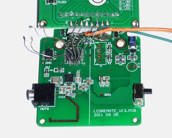
[Richard] started by opening up the remote and taking a look at the radio circuitry. He discovered the circuit uses a nRF24L01+ chip. He had previously picked up a couple of these on eBay, so his first thought was to just promiscuously snoop on the communications over the air. Unfortunately the chips can only listen in on up to six addresses at a time, and with a 40-bit address, this approach may have taken a while.

Not one to give up easily, [Richard] chose a new method of attack. First, he knew that the radio chip communicates to a master microcontroller via SPI. Second, he knew that the radio chip had no built-in memory. Therefore, the microcontroller must save the address in its own memory and then send it to the radio chip via the SPI bus. [Richard] figured if he could snoop on the SPI bus, he could find the address of the remote. With that information, he would be able to build another radio circuit to listen in over the air.

Using an Open Logic Sniffer, [Richard] was able to capture some of the SPI communications. Then, using the datasheet as a reference, he was able to isolate the communications that stored information int the radio chip’s address register. This same technique was used to decipher the radio channel. There was a bit more trial and error involved, as [Richard] later discovered that there were a few other important registers. He also discovered that the remote changed the address when actually transmitting data, so he had to update his receiver code to reflect this.

The receiver was built using another nRF24L01+ chip and an Arduino. Once the address and other registers were configured properly, [Richard's] custom radio was able to pick up the radio commands being sent from the lighting remote. All [Richard] had to do at this point was press each button and record the communications data which resulted. The Arduino code for the receiver is available on the project page.

[Richard] took it an extra step and wrote his own library to talk to the flashes. He has made his library available on github for anyone who is interested.


Filed under: Arduino Hacks, radio hacks

Arduino Translates Signals Between Steering Wheel Buttons and Aftermarket Head Unit

There is no question that steering wheel mounted controls are super convenient. Reaching all the way over to the dashboard to change a radio station is so 1990’s. An ever-increasing percentage of new cars are coming equipped with steering wheel controls for the stereo, however, you’ll lose the button control if you change out the stock head unit to something a little higher in quality. Sure, there may be an adapter readily available for your car/stereo combination, but there also may not be. [Ronnied] took the DIY road and made his own adapter.

The first obstacle for [Ronnied] was to figure out the wiring on the steering wheel controls. After some poking around he found that there were only two wires used for all of the control buttons, each button only changing the resistance between the two wires. The button states could easily be read by using an Arduino’s analog input. A Pro Mini model was chosen for its small size as it could be housed in the radio compartment of the dash.

The next step was getting the Arduino to control the aftermarket head unit. [Ronnied] did some research regarding JVC’s Stalk digital control interface but came to the conclusion that it would be easier to direct wiring the Arduino outputs to the appropriate spot on the head unit’s circuit board. To do this the button for each function that would also be represented on the steering wheel was traced out to find a common point on the circuit board. Jumper wires soldered to the circuit board simply allow the Arduino to emulate button pushes. To ensure that the head unit buttons still work in conjunction with the steering wheel buttons, the Arduino would have to keep the pins as inputs until a steering wheel button was pushed, the pin changed to an output, the signal sent and the pin changed back to an input. This feature was easily created in the Arduino sketch.

Video below.


Filed under: radio hacks
Hack a Day 28 Sep 18:00