Cheap 433 MHz wireless switches are a tempting way to enter the world of home automation, but without dedicated hardware, they can be less easy to control from a PC. That’s the position [TheStaticTurtle] was in, so the solution was obvious. Build a USB 433 MHz transceiver.
At the computer end is a CH340 USB-to-serial chip and the familiar ATmega328 making this a compact copy of the Arduino. At the RF end are a pair of modules for transmit and receive, unexpectedly with separate antennas. This device is a second revision, after initial experiments with a single antenna connector and an RF switch proved not to work. On the software side the Arduino uses the rc-switch library, while on the PC side there’s a Python library to make sense of it all. The code and hardware files are all on GitHub, should you wish to experiment.
The problem of making a single antenna transceiver is not for the faint-hearted RF engineer, as while diode switches seem on paper to deliver the goods, they can be extremely difficult to get right and preserve linearity. We’re curious that a transceiver module wasn’t used instead, but we’re guessing that cost played a significant part in the equation.
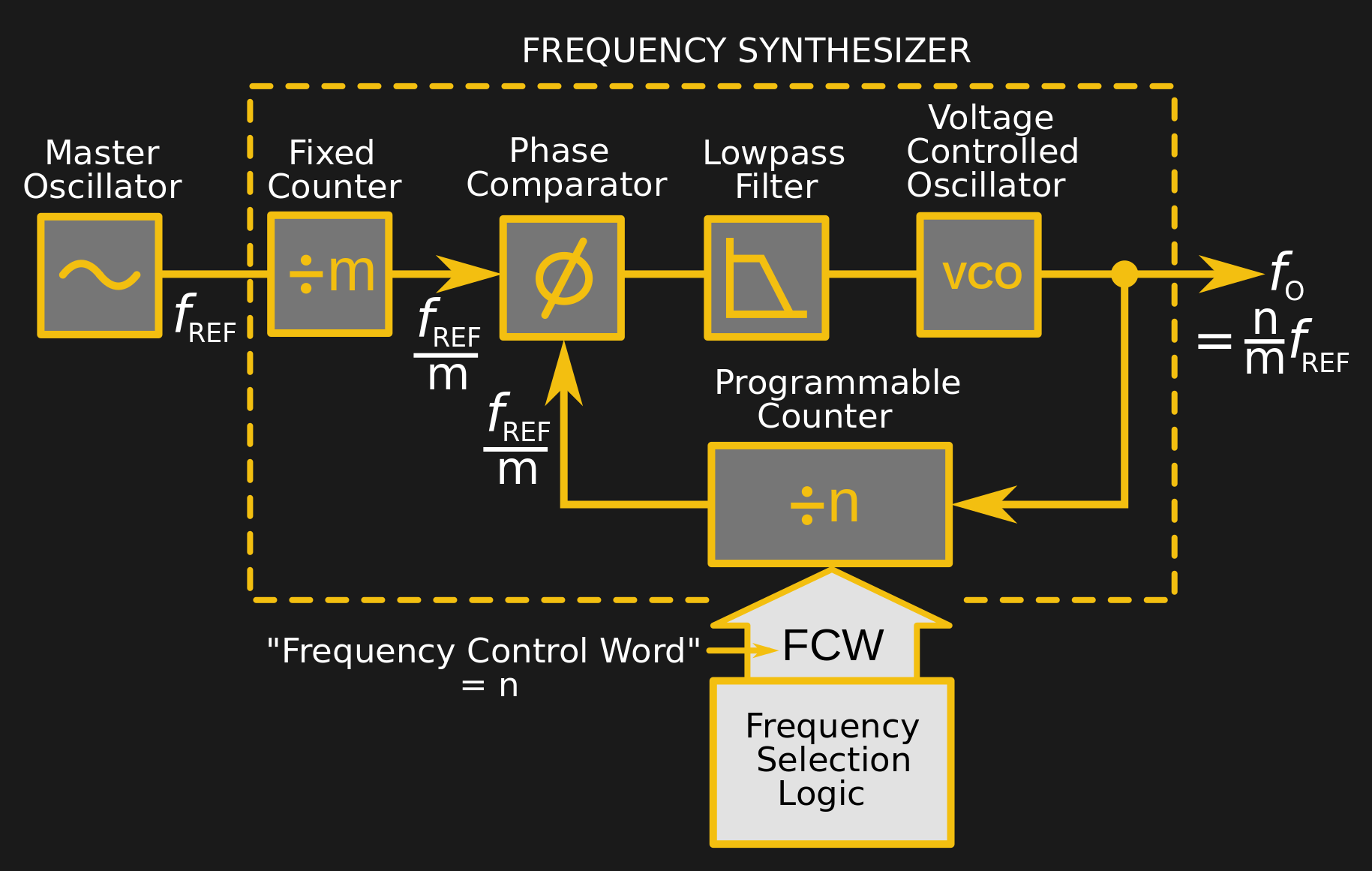
At the heart of many amateur radio and other projects lies the VFO, or Variable Frequency Oscillator. Decades ago this would have been a free-running LC tuned circuit, then as technology advanced it was replaced by a digital phase-locked-loop frequency synthesiser and most recently a DDS, or Direct Digital Synthesis chip in which the waveform is produced directly by a DAC. The phase-locked loop (PLL) remains a popular choice due to ICs such as the Si5351 but is rarely constructed from individual chips as it once might have been. [fvfilippetti] has revisited this classic circuit by replacing some of its complexity with an Arduino (Spanish language, Google Translate link).
A PLL is a simple circuit in which one oscillator is locked to another by controlling it with a voltage derived from comparing the phase of the two. Combining a PLL with a set of frequency dividers creates a frequency synthesiser, in which a variable frequency oscillator can be locked to a single frequency crystal with the output frequency set by the division ratios. The classic PLL chip is the CMOS 4046 which would have been combined with a pile of logic chips to make a frequency synthesiser. The Arduino version uses the Arduino’s internal peripherals to take the place of crystal oscillator, dividers, and phase comparator, resulting in an extremely simple physical circuit of little more than an Arduino and a VCO for the 40 metre amateur band. The code can be found on GitLab, should you wish to try for yourself.
It would be interesting to see how good this synthesiser is at maintaining both a steady frequency and minimal phase noise. It’s tempting to think of such things as frequency synthesisers as a done deal, so it’s always welcome to see somebody bringing something new to them. Meanwhile if PLLs are new to you, we have just the introduction for you.
It is getting harder and harder to tell homemade projects from commercial ones. A good case in point is [Mirko’s] all band radio which you can see in the video below the break. On the outside, it has a good looking case. On the inside, it uses a Si4730 radio which has excellent performance that would be hard to get with discrete components.
The chip contains two RF strips with AGC, built-in converters to go from analog to digital and back and also has a DSP onboard. The chip will do FM 64 to 108 MHz and can demodulate AM signals ranging from 153 kHz to 279 kHz, 520 kHz to 1.71 MHz, and 2.3 MHz to 26.1 MHz. It can even read RDS and RBDS for station information. The output can be digital (in several formats) or analog.
The radio takes serial (I2C) commands, and the Arduino converts the user interface so that you can control it. The chip comes in several flavors, each with slightly different features. For example, the Si4731 and Si4735 have the RDS/RBDS decoder, and the shortwave mode is available on Si4734 and Si4735. Confused? Page 2 of the programming guide should help. According to [Mirko], he used a 4730, but it still did shortwave with the 4735 library.
Breakout boards with the chip are just a few bucks. It appears the chip has the technical capability to receive single sideband, but it requires a poorly documented patch. It is in recent versions of this library, though.
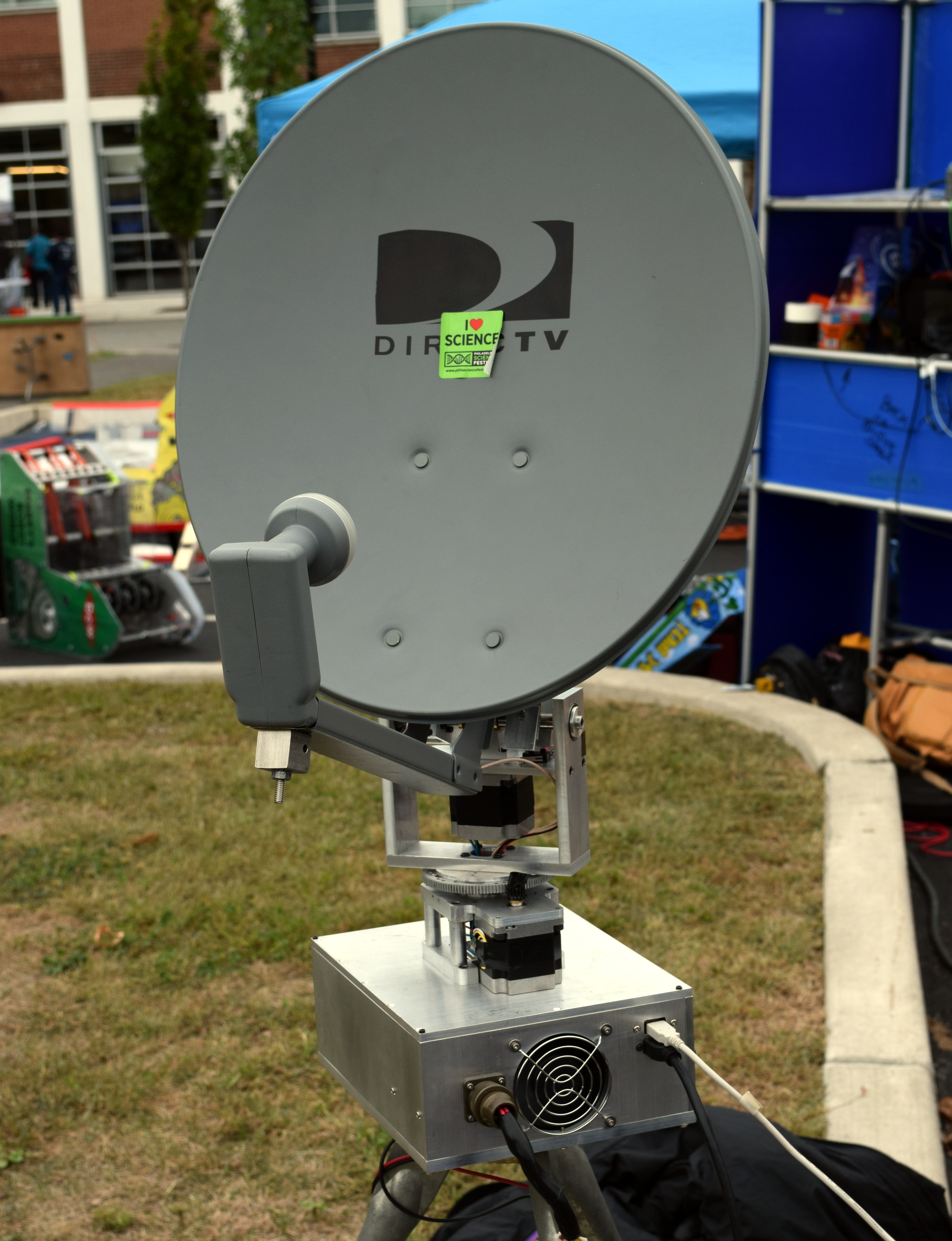
You probably wouldn’t expect to see somebody making astronomical observations during a cloudy day in the center of a dense urban area, but that’s exactly what was happening at the recent 2019 Philadelphia Mini Maker Faire. Professor James Aguirre of the University of Pennsylvania was there demonstrating the particularly compact Mini Radio Telescope (MRT) project built around an old DirecTV satellite dish and a smattering of low-cost components, giving visitors a view of the sky in a way most had never seen before.
Thanks to the project’s extensive online documentation, anyone with a spare satellite dish and a couple hundred dollars in support hardware can build their very own personal radio telescope that’s capable of observing objects in the sky no matter what the time of day or weather conditions are. Even if you’re not interested in peering into deep space from the comfort of your own home, the MRT offers a framework for building an automatic pan-and-tilt directional antenna platform that could be used for picking up signals from orbiting satellites.
With the slow collapse of satellite television in the United States these dishes are often free for the taking, and a fairly common sight on the sidewalk come garbage day. Perhaps there’s even one (or three) sitting on your own roof as you read this, waiting for a new lease on life in the Netflix Era.
Whether it’s to satisfy your own curiosity or because you want to follow in Professor Aguirre’s footsteps and use it as a tool for STEM outreach, projects like MRT make it easier than ever to build a functional DIY radio telescope.
Point and Shoot
The MRT, and really any radio telescope project like this, is essentially made up of two separate systems: one that provides the motorized aiming of the dish, and the receiver that actually captures the signals. Either system could work independently of the other, but when combined with the appropriate software “glue”, they allow the user to map the sky in radio frequencies.
Obviously, the electronics and mechanical components required to pan an antenna across the sky aren’t terribly complex. If you wanted to keep things really simple and were content with moving in a single axis, you could even do it with a “barn door” tracker. What’s really kicked off the recent explosion of DIY radio telescopes is the RTL-SDR project and the era of low-cost Software Defined Radios (SDRs) it’s inspired.
Unsurprisingly, the MRT also uses an RTL-SDR receiver for processing signals from the Low-Noise Block (LNB) in the dish. Professor Aguirre says that since they are still using the stock DirecTV LNB, the telescope is fairly limited in what it can actually “see”. But it’s good enough to image the sun or pick up satellites in orbit, which is sufficient for the purposes of demonstrating the basic operating principles of a radio telescope.
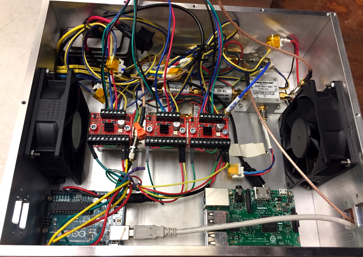
To move the satellite dish, the MRT is using an Arduino connected to a trio of Big Easy Drivers from Sparkfun. These are in turn connected to the stepper motors in the antenna mount, which are sufficiently geared so they can move the dish around without the need for a counterweight. This makes it an excellent candidate for enclosure inside a dome, which would allow for all-weather observations.
Both the RTL-SDR receiver and the Arduino are connected to a Raspberry Pi, which runs the software for the telescope and provides the interface for the user. The MRT GitHub repository contains all of the various tools and programs created for the project, mostly written in Python, which should provide a useful reference even if you’re not interested in duplicating the telescope’s overall design.
Wandering Through the Sky
When we visited Professor Aguirre, he was attempting to use the MRT to find the Sun. You’d think that a simple enough task in the middle of the afternoon, but thanks to an unbroken layer of steel-gray clouds hanging low in the October sky, Sol was absolutely nowhere to be found with our meager human senses.
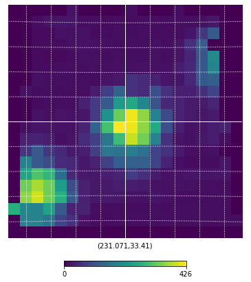
Geostationary satellites as seen by the MRT
As the dish made its slow robotic pans across the sky, we spoke with the Professor about the telescope and the various revisions it went through over the years. Eventually the display lit up, showing a representation of an unusually strong signal, clearly the MRT was hearing something out there. After brief scrutiny, the Professor announced that we hadn’t found the sun; instead, the telescope most likely crossed paths with a geostationary satellite.
It was this raconteur style of discovery that kept visitors to the Mini Radio Telescope enthralled. Nobody expected this hacked together contraption of consumer-grade hardware to discover a new exoplanet or help solve some long-pondered mystery of the cosmos while sitting in a Philadelphia parking lot.
But it was more than capable of pointing out objects tens of thousands of kilometers away while our own eyes couldn’t even figure out where the Sun was. It reaffirmed in a very real way that something was out there, and students both young and old couldn’t help but be fascinated by it.
The field of radio control has benefited much from the onward march of technology. Where a basic 2-channel setup would once have cost hundreds of dollars, it’s now possible to get a high-end 2.4GHz 9-channel rig for well under $100, shipped to your door. However, the vast majority of these systems are closed-source and built for purpose. Sometimes, there are benefits to doing things your own way, and that’s precisely what this project does.
At its heart, it’s a simple combination. An Arduino Pro Mini talks to a NRF24L01 which handles the wireless communication. At that point, it’s up to you – throw in as few or as many controls as you like. For this build, [HowToMechatronics] has gone with a twin-stick setup, with a pair of potentiometers and twin toggle switches to round out the options.
The build comes in handy, as it’s possible to program in whatever features you may need for a given project. [HowToMechatronics] has used it to control a hexapod robot, among other projects. It’s a build that shows that with cheap and readily available parts, it’s possible to whip up a custom solution to suit your needs.
There are a multitude of radio shields for the Arduino and similar platforms, but they so often only support one protocol, manufacturer, or frequency band. [Jan Gromeš] was vexed by this in a project he saw, so decided to create a shield capable of supporting multiple different types. And because more is so often better, he also gave it space for not one, but two different radio modules. He calls the resulting Swiss Army Knife of Arduino radio shields the Kite, and he’s shared everything needed for one on a hackaday.io page and a GitHub repository.
Supported so far are ESP8266 modules, HC-05 Bluetooth modules, RFM69 FSK/OOK modules, SX127x series LoRa modules including SX1272, SX1276 and SX1278, XBee modules (S2B), and he claims that more are in development. Since some of those operate in very similar frequency bands it would be interesting to note whether any adverse effects come from their use in close proximity. We suspect there won’t be because the protocols involved are designed to be resilient, but there is nothing like a real-world example to prove it.
[Kerry Wong] comes across the coolest hardware, and always manages to do something interesting with it. His widget du jour is an old demo board for a digital RF attenuator chip, which can pad a signal in discrete steps according to the settings of some DIP switches. [Kerry]’s goal: forget the finger switch-flipping and bring the attenuator under Arduino control.
As usual with his videos, [Kerry] gives us a great rundown on the theory behind the hardware he’s working with. The chip in question is an interesting beast, an HMC624LP4E from Hittite, a company that was rolled into Analog Devices in 2014. The now-obsolete device is a monolithic microwave integrated circuit (MMIC) built on a gallium arsenide substrate rather than silicon, and attenuates DC to 6-GHz signals in 64 steps down to -31.5 dBm. After a functional check of the board using the DIP switches, he whipped up a quick Arduino project to control the chip with its built-in serial interface. It’s just a prototype for now, but spinning the encoder is a lot handier than flipping switches, and once this is boxed up it’ll make a great addition to [Kerry]’s RF bench.
There’s an old saying that the nice thing about standards is there are so many of them. For digital voice modes, hams have choices of D-Star, DMR, System Fusion, and others. An open source project, the Multimode Digital Voice Modem (MMDVM), allows you to use multiple modes with one set of hardware.
There are some kits available, but [flo_0_] couldn’t wait for his order to arrive. So he built his own version without using a PCB. Since it is a relatively complex circuit for perf board, [flo_0_] used Blackboard to plan the build before heating up a soldering iron. You can see the MMDVM in action below.
[Tom Hall], along with many hams around the world, have been hacking the Silicon Labs Si5351 to create VFOs (variable frequency oscillators) to control receivers and transmitters. You can see the results of his work in a video after the break.
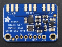
[Tom] used a Teensy 3.1 Arduino compatible board, to control the Si5351 mounted on an Adafruit breakout board. An LCD display shows the current frequency and provides a simple interface display for changing the output. A dial encoder allows for direct adjustment of the frequency. The ham frequency band and the frequency increment for each encoder step are controlled by a joystick. When you get into the 10 meter band you definitely want to be able to jump by kHz increments, at least, since the band ranges from 28 mHz to 29.7 mHz.
So what is the Si5351? The data sheets calls it an I2C-Programmable Any-Frequency CMOS Clock Generator + VCXO. Phew! Let’s break that down a bit. The chip can be controlled from a microprocessor over an I2C bus. The purpose of the chip is to generate clock outputs from 8 kHz to 160 kHz. Not quite any frequency but a pretty good range. The VCXO means voltage controlled crystal oscillator. The crystal is 25 mHz and provides a very stable frequency source for the chip. In addition, the Si5351 will generate three separate clock outputs.
[Tom] walks through the code for his VFO and provides it via GitHub. An interesting project with a lot of the details explained for someone who wants to do their own hacks. His work is based on work done by others that we’ve published before, which is what hacking is all about.
The name of the game in rocketry or ballooning is weight. The amount of mass that can be removed from one of these high-altitude devices directly impacts how high and how far it can go. Even NASA, which estimates about $10,000 per pound for low-earth orbit, has huge incentives to make lightweight components. And, while the Santa Barbara Hackerspace won’t be getting quite that much altitude, their APRS-enabled balloon/rocket tracker certainly helps cut down on weight.
Tracksoar is a 2″ x .75″ x .5″ board which weighs in at 45 grams with a pair of AA batteries and boasts an ATmega 328P microcontroller with plenty of processing power for its array of on-board sensors. Not to mention everything else you would need like digital I/O, a GPS module, and, of course, the APRS radio which allows it to send data over amateur radio frequencies. The key to all of this is that the APRS module is integrated with the board itself, which saves weight over the conventional method of having a separate APRS module in addition to the microcontroller and sensors.
As far as we can see, this is one of the smallest APRS modules we’ve ever seen. It could certainly be useful for anyone trying to save weight in any high-altitude project. There are a few other APRS projects out there as well but remember: an amateur radio license will almost certainly be required to use any of these.


 [Tom] used a Teensy 3.1 Arduino compatible board, to control the Si5351


