Posts with «nano» label

This Arduino G meter shows how fast your car really is!

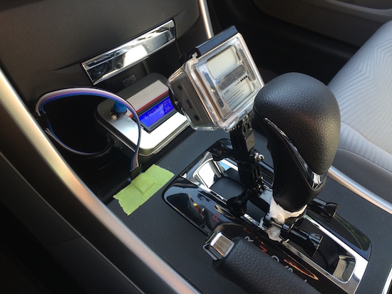
Using an Arduino with an accelerometer, this handy display lets you know how “extreme” your driving really is!

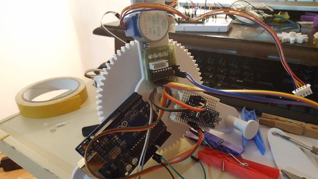
Modern cars tell us all kinds of information about how our vehicles are working and how you are driving. One thing that is generally missing is a display that tells you how many “G’s” (or how much you are pushed back into your seat) your car is pulling. With this clever setup, you can know how much force your tires are putting to the ground (neglecting body-roll factors) in both straight-line acceleration, braking, and even side-to-side turning.

As an automotive enthusiast and a mechanical engineer, I had a poor physical understanding of G’s. Sure, I’m experiencing 1g as I’m standing upright, but how many G’s did I experience as I came to a quick stop in LA traffic? To gain a better physical understanding of G’s, I built this device.

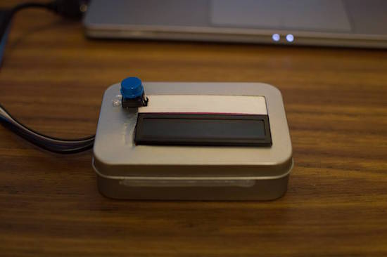
You can see more details of this simple yet very useful build on eadiec’s Imgur page.

Arduino Blog 11 Oct 19:55
arduino  featured  g meter  nano  

Capture time-lapses with a steel and aluminum camera slider

Using an Arduino, along with a stepper motor and ball bearings, YouTuber GreatScott! has created a very smooth camera slider.

Time-lapse sequences can be interesting on their own, but if you can add motion to the camera, this adds a really neat element. To give a little extra flair to his video production, GreatScott! built his own motorized slider using stainless steel and aluminum parts. Movement is accomplished via an Arduino Nano controlling a stepper motor, and ball bearings are used to keep the shots smooth. You can see the results and process in the two-part video sequence below.

In this project, I will show you how I repurposed two old camera tripods in order to create a motorized camera slider. The mechanical system consist mostly of aluminium and stainless steel which makes the slider sturdy and pretty decent looking. The electrical system consists of an Arduino Nano with LCD, rotary encoder, limit switches and stepper motor.

Besides the videos seen here, check out GreatScott!’s Instructables writeup as well.

A room light controller with its own light display

Hansi (aka “Natural Nerd”) wasn’t content simply controlling his room’s lighting, so he had his control box illuminate along with it!

In order to control lighting intensity, you could hook up a potentiometer directly, but Hansi decided to instead connect four potentiometers to an Arduino Nano to control an external light source. These four inputs are attached to analog pins on the Arduino, which control a strip of RGB LEDs inside of a partially translucent box. When the knobs are turned, the number of LEDs on display increase or decrease, in different colors depending on which it turned. An external light can then be controlled along with the beautiful controller display.

This Instructable will show you how I made a control panel that has three 12 volt power output ports which can be controlled with knobs at the front. I will be connecting the lighting in my basement to the three outputs, so that it can be controlled through the panel.

The panel has a nice and ambient light pulsation when it’s passive, and when you turn the knobs, the internal light indicates how much the knob is turned, with a separate color for each knob.

Intrigued? You can check out the project’s page on Instructables, and find the Arduino code here.

EasyEDA RGB5050 LED Scroll Bar


Guest Post Disclaimer

This is a guest post by the EasyEDA team. I would like to thank EasyEDA for providing this tutorial for everyone to enjoy. All information within this post was provided by EasyEDA.


Description

None of us could deny the fact that we would love with to play with LED’s and lighting stuff. I love to play with LED’s and create attractive lighting effects. This project was a result of such an attempt where I created a stunning RGB light effect using the popular development platform Arduino Nano. Let’s see the circuit, code and instruction on building this project:


Image source: EasyEDA


Arduino Libraries and IDE

No libraries are required for this project. The Arduino IDE can be downloaded from the Arduino website. Here is the download link.

ARDUINO CODE:


Preparing the LED strips

Cut down the LED strips into 10 single pieces. Make sure you cut them into equal halves and make sure that only the copper conduction plate in the strip is cut. Making a wrong cut disrupts the electrical conductivity between the LED’s. After cutting down into separate strips, you will need to connect each strip using a Dupont wire connectors.

Image source: EasyEDA


Designing the Control Board

I have made a custom control board that incorporates an Arduino Nano. The control board is used to boost the incoming signal from Arduino and lights up the corresponding LED strips.


Image source: EasyEDA


Control Board Circuit diagram

I used a free Online circuit and PCB designing platform called EasyEDA to develop my control board. It is pretty easy to use especially because of the large library of parts to choose from. Once the design is complete, you have the option to order it through EasyEDA. They offers great prices on custom PCB manufacturing. I have added 10 connection points for 10 LED strips. Each RGB LED strip is controlled by one of the Arduino Nano digital pins.. Transistors Q1,Q2,Q3….Q10 act as a switch for these LED strips for controlling 12V strips via a 5V signal from the Arduino. And switches S1,S2..S4 were added to be able to select the effect on the strip. The schematic can be seen below:


Schematic

You can access the actual EasyEDA schematic by clicking on the image below:

Image source: EasyEDA


PCB Board Design

Here is the PCB board design for this project.
You can access the actual EasyEDA design by clicking on the image below.

Image source: EasyEDA


PCB Fabrication

After completing the PCB design, you can click on the Fabrication icon.

You will then have access to the PCB order page which will allow you to download your PCB Gerber files that can be sent to any manufacturer. However it is a lot easier (and cheaper) to order it directly from EasyEDA.
Here you can select:

  • the number of PCBs you want to order
  • the number of copper layers you need
  • the PCB thickness
  • copper weight
  • and even the PCB color
After you’ve selected all of the options, click “Save to Cart” and complete you order. You will then get your PCBs shipped a few days later.

Image source: EasyEDA


PCB final product

When I received the PCBs, I am quite impressed with the quality, they are pretty nice.

Image source: EasyEDA


PCB Build of Materials

Image source: EasyEDA


PCB connections

Connect the LED strips through the connection points in the board. Make sure that you connect these correctly (push the connectors all the way onto the pin), because the chances of a short increase significantly with the number of wires connected. Once all the connections are done all that left is to install your Arduino Nano (pre-programmed with the Arduino code above), and to power the PCB with a 12V power supply.


Image source: EasyEDA


Project Video


Concluding comments

Hope you like this RGB light effects project, do try it out and post your feedback below.
 
Disclaimer:
This is a guest blog post by the EasyEDA team. All information within this post was provided by EasyEDA.

ScottC 11 Sep 07:09

Motion-activated bed lighting system for nighttime wandering

Rather than stumble around in the dark or blind himself with a bedside lamp, Maker Scott Clandinin has come up with an Arduino-powered, motion-activated lighting system for nighttime wandering.

The setup is fairly simple. A PIR sensor detects movement, which automatically triggers a hidden strip of RGB LEDs to illuminate a path as you get out of bed. An RTC module keeps the time and ensures that the lights only turn on between 9pm and 8am. (The good news is that the strip will only stay lit for approximately two minutes, and won’t keep you up for the rest of the night.) A small capacitive touch sensor on the bottom of its case can also be used to test the lighting display outside of operational hours. 

Tired of bumping into things or having to find the switch? Then check out Clandinin’s entire project on Hackaday.io.

Relive the ‘80s with a MIDI-controlled Scanjet keytar

The ‘80s may be long gone, but James Cochrane is bringing the keytar back with the help of an old HP Scanjet. For this, the Maker has taken an Arduino, a stepper motor shield, an optocoupler and an off-the-shelf MIDI keyboard for input, and integrated it into the flatbed scanner’s original features. The end result: the world’s first (and only) MIDI-controlled HP Scanjet keytar.

As he describes in his YouTube video:

This scanner had a hidden command set within the Scanner Control Language which allows you to send musical notes directly to the stepper motor. This is a tedious method where you have to enter the notes and durations manually into a text file (similar to G-code on a CNC machine). I have always used and will always use this method for my old school music videos; however, I wanted to try and build a MIDI-controlled stepper motor.

One day I had one of my HP Scanjets sitting on its side and for some reason it resembled a Roland SH-101 and that’s when I came up with the idea for the HP Scanjet Keytar. What a great way to merge both into a musical instrument.

Those wishing to relive the days of classic yet quirky keytar are in luck. Cochrane has provided a detailed breakdown of the device in the video below, and has shared its code on GitHub.

Star Track is an Arduino-powered star pointer and tracker

Maker and astronomy enthusiast Görkem Bozkurt has built a GoTo telescope mount-inspired system that points and tracks any object in the sky using its celestial coordinates. The aptly named Star Track sports a 3D-printed structure along with a pair of Arduinos (an Uno and Nano), a gyroscope, an RTC module, two low-cost 5V stepper motors, and a laser pointer.

Many computerized telescopes have a type of telescope mount and related software which can automatically point a telescope to astronomical objects that the user selects. Called GoTo mounts. Like a standard equatorial mount, equatorial GoTo mounts can track the night sky by driving the right-ascension axis. Since laser pointers are a perfect way to point stars, I thought a laser pointer with a GoTo mount would be a perfect tool for locating stars and to track them.

First I had to design a two-axis mount.

1. 360-degree rotating axis for RA
2. A up-down axis for DEC

After aligning the RA axis with the North Celestial Pole, an Arduino connected with an RTC should be able to calculate and track RA with sidereal time. And you can adjust the two axes to the user input from a computer via serial.

But first I had to find a way to precisely point the mount to given degrees. The main idea was to use step motors and give them a specific step to take. But after a few tests that was not totally accurate.

Instead, I used a gyroscope placed on the laser pointer to track the degrees on the two axes, this way I was able to send a command to the step motor to start and stop the movement if necessary.

Intrigued? Bozkurt provides a basic overview of positional astronomy on his project page, along with all of Star Track’s 3D files, code and assembly instructions.

This Arduino machine will sort your Skittles by color

Do you just really hate yellow Skittles? Only love the red ones? Well, why waste your time sorting them out yourself when an automated machine can do it for you? As part of a recent tutorial, Dejan Nedelkovski has built what we calls the “Arduino Color Sorter” using a TCS3200 color sensor, two hobbyist servo motors, and an Arduino Nano.

How it works is fairly straightforward: The candies are stored within a plastic tube on top of the contraption and dropped onto a platform attached to the first servo. The motor then rotates the platform, bringing the Skittle to the color sensor. From there, the bottom servo moves into position while the top servo rotates again until the candy falls into the guide rail and into its respective bin.

So whether you’re tired of grouping your Skittles or need to meet the request of rockstars like Van Halen (no brown M&Ms!), you can find the Arduino Color Sorter’s 3D model, code and instructions here.


The CALEIDUINO is a digital and sound reactive kaleidoscope

The CALEIDUINO is an Arduino-based digital and sound reactive kaleidoscope, designed to serve as a toy, an art object, and a tool for teaching electronics and programming in a playful yet creative way.

At the heart of CALEIDUINO is a PCB for connecting an Arduino Nano, a TFT 1.8 “display, an analog 3-axis accelerometer GY-61, a piezoelectric, a switch, and a 9V battery–all of which are housed inside a hexagonal methacrylate case. Just like in any kaleidoscope, t three mirrors in triangular prism shape, while an accelerometer collects a user’s movement to generate the psychedelic graphics and sounds.

In terms of software, the CALEIDUINO uses the Arduino IDE along with the Adafruit GFX and ST7735 libraries. The project is entirely open source and is the work of artist José Manuel González. You can read more about the device here, or see it in action below.