Posts with «nano» label

Pong embedded in a vintage Sony Watchman with Arduino

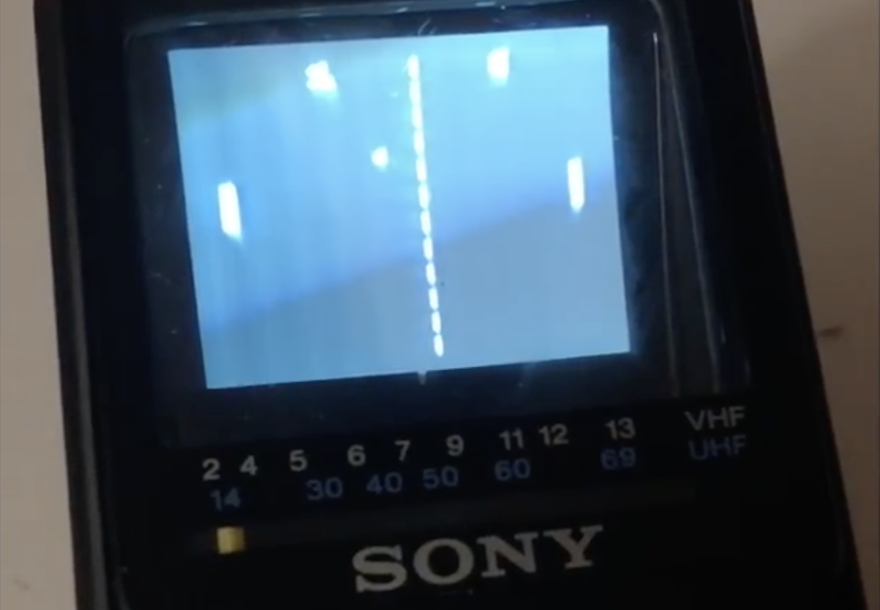
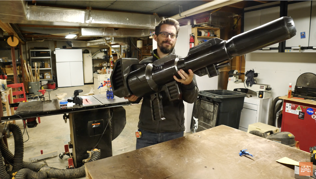
There’s perhaps no other game more classic than Pong, and likely none that require fewer control inputs, making it perfect for “porting” to a Sony Watchman. While an amazing piece of tech when introduced in the early ’80s, the current lack of analog TV signals means they only receive static.

As seen here, hacker “sideburn” decided to do something about it, and removed the tuner and decoder chip, making space for an Arduino Nano in the device’s housing. To complete the build, he hooked up the Arduino outputs to TV inputs, along with the tuner as a paddle controller and built-in switch as a start/pause button, and was able to seal the unit up again.

The result is a retro gaming system that looks completely stock, playing Pong as if it was there the whole time. Be sure to check out the video to see it in action!

Automate a rubber strip door with Arduino

In order to separate their office and shop areas, NYC CNC installed a rubber strip assembly that had to be pushed out of the way every time someone wanted to walk through. Although functional, it was also quite annoying, so they installed a system that uses a pneumatic cylinder to automatically move the rubber strips out of the way.

The device uses an Arduino Nano for control and VL53L0X  time-of-flight sensors for presence detection. In addition, it features a clever gear and belt assembly to mirror one side of the door with the other.

You can find more details of the build in the video below and check out the project’s components, Fusion 360 design files, and Arduino code here.

Measure RPM with an IR sensor and Arduino

When dealing with robotics and other electronics projects, it can be important to know how many revolutions a motor is making. From here, you can infer the distance that your device has traveled, or any number of other important variables.

If you’d like to get started with this type of sensing, this electronoobs tutorial will show you how to get things hooked up using an Arduino and a computer, along with an oscilloscope to verify measurements up to 10,000 RPM.

In his setup, an IR emitter/receiver bounces light off a spinning object. When light reflects back, it opens the circuit, causing the output to be grounded via a pulldown resistor, telling you that a revolution has been made. The 3D-printed device also features an OLED screen.

To emit infrared light we need a IR LED and to detect it a IR sensible transistor. Usually you could find those as a one unique module. To amplify the signal I’ve used the LM324 amplifier. You will also need a 100 ohm resistor and a 4.7k ohm one. To supply the system we will need a basic 9V battery and connector, an Arduino Nano, and an OLED screen. The case is 3D printed…

You can find more details on the build process here, as well as a demo of the tachometer below!

Arduino Blog 27 Feb 20:09

YouTuber creates an organ out of 44 Furbies

If you think Furbies have become extinct, think again, as musical hacker “Look Mum No Computer” has decided to revive a number of them to create his own Furby Organ.

To make this horrifying yet awesome instrument, he placed 44—yes, 44—of these strange creatures on top of an organ frame with a keyboard and several dials, along with a switch labeled ominously as “collective awakening.”

Each individual Furby is controlled by two Arduino Nano boards, and as you might imagine, the whole project took a massive amount of work to wire things together. You can see the incredible results in the first video below, while the second gives a bit more background on the device’s origin.

Arduino Blog 12 Feb 21:01

Recreate Optimus Prime’s blaster with Arduino

YouTuber Bob Clagett has dreamed of creating his own life-sized Optimus Prime ion blaster for years, and now after hours of 3D printing and finishing, he finally has something worthy of that universe.

While he opted to construct it in a 1:2 scale, it’s still an impressive physical build, looking comically large, but not entirely unwieldy as a full-sized 8-foot blaster would have been.

Inside, sound and lighting effects are controlled by an Arduino, which plays clips from the show and flashes in different patterns via an Adafruit sound board and RGB LED strip.

I wanted the blaster to play sounds and have lights come out of the barrel so I rigged up an Arduino Nano with an Adafruit sound board and amp that would cycle blaster sounds and lights when a button was pressed. And because there’s always more than meets the eye, I had a separate button that played just Transformers sound clips. To defuse the LED strip when the lights fired, I printed a semi-translucent disc that would stand-off from the sides so that sound could still escape, but the light would be diffused. I decided to mount all of the audio components in the barrel so that the cannon could be taken apart to charge the battery back.

You can see the entire process in the video below, or check out his post for a summary.

Add an Arduino-based tachometer to your CNC router

In order to get a good cut with a CNC router, the cutting tool speed needs to be properly set. Since his CNC didn’t come with RPM feedback, Troy Barbour came up with his own solution using an Arduino Nano along with an IR emitter/sensor pair.

The spindle was set up with a single reflective surface, enabling it to sense one pulse per revolution that is sent to the Arduino at up to up to 30,000 RPM. To ensure accurate measurement, the device was programmed using an interrupt, meaning that if another process is running, it will temporarily drop what it’s doing and count the incoming pulse.

RPM is displayed on a tiny OLED screen, which shows both an RPM number as well as a dial indicator for quick reference.

Build an optical RPM indicator for your CNC router with an Arduino Nano, an IR LED/IR photodiode sensor and an OLED display for less than $30. I was inspired by eletro18’s Measure RPM – Optical Tachometer Instructable and wanted to add a tachometer to my CNC router. I simplified the sensor circuit, designed a custom 3D-printed bracket for my Sienci CNC router. Then I wrote an Arduino sketch to display both a digital and analog dial on an OLED display.

You can see it in action below, and find build instructions and code on Barbour’s write-up.

Fall asleep with the help of LEDs and an Arduino

While some fall asleep nearly immediately with no assistance, others need the drone of a fan or a dedicated noisemaker to help them relax. The Fall Asleep Device, also known as “FADing,” by Youz takes a different approach. FADing shines an LED onto the ceiling out via a piece of acrylic, so that you can use it whether you like to sleep on your back or side.

An Arduino Nano controls the nicely-shaped wooden unit, and causes light to fade in and out at a pace that decreases from 11 to 6 pulses per minute, prompting you to regulate and relax your breathing accordingly.

After being started by a button below, FADing is kept on by a relay until it finishes, meaning it uses no power in standby. You can check it out in the video below, and find build instructions and code in Youz’s write-up.

Optical Tach Addresses the Need for Spindle Speed Control

With CNC machines, getting the best results depends on knowing how fast your tool is moving relative to the workpiece. But entry-level CNC routers don’t often include a spindle tachometer, forcing the operator to basically guess at the speed. This DIY optical spindle tach aims to fix that, and has a few nice construction tips to boot.

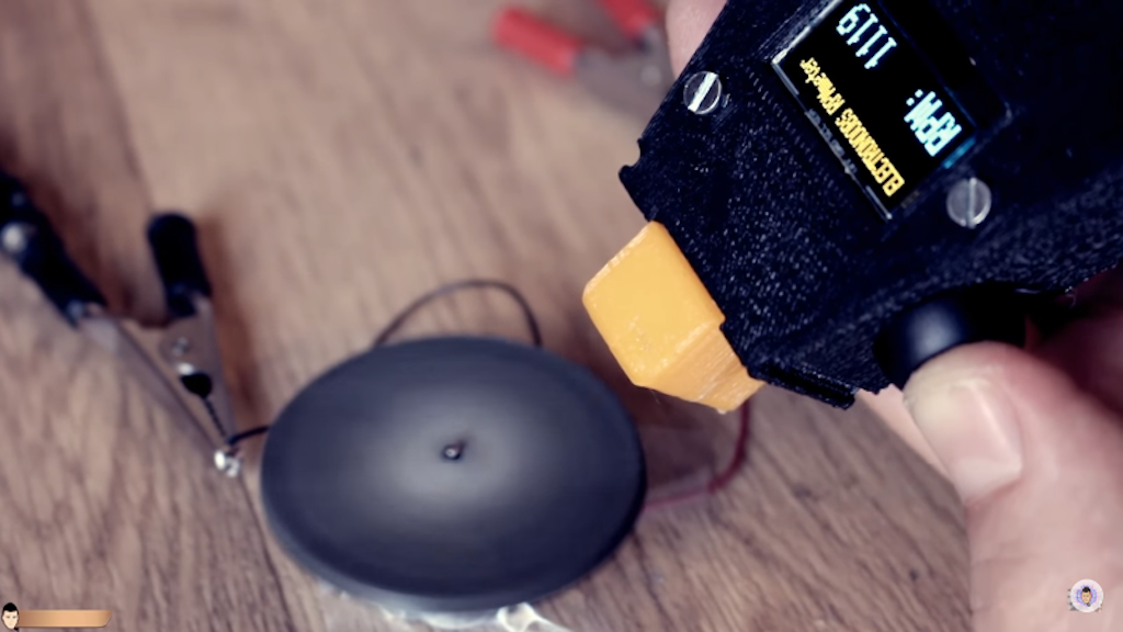
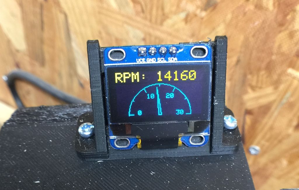
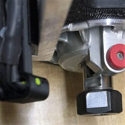
The CNC router in question is the popular Sienci, and the 3D-printed brackets for the photodiode and LED are somewhat specific for that machine. But [tmbarbour] has included STL files in his exhaustively detailed write-up, so modifying them to fit another machine should be easy. The sensor hangs down just far enough to watch a reflector on one of the flats of the collet nut; we’d worry about the reflector surviving tool changes, but it’s just a piece of shiny tape that’s easily replaced.  The sensor feeds into a DIO pin on a Nano, and a small OLED display shows a digital readout along with an analog gauge. The display update speed is decent — not too laggy. Impressive build overall, and we like the idea of using a piece of PLA filament as a rivet to hold the diodes into the sensor arm.

Want to measure machine speed but don’t have a 3D printer? No worries — a 2D-printed color-shifting tach can work too.

Hack a Day 28 Jan 09:01

The Edgytokei is a nunchucks-inspired edge clock

Just when you thought you’d seen every possible hacked clock design, creator Ekaggrat Singh Kalsi has come up with something new: a faceless clock that is able to tell time with two hands that never make a full rotation.

Instead, an Arduino Nano powers a novel mechanical gear assembly via two motors, which causes the two hands to physically switch positions between the second arm being mounted on the base and on the tip of the first arm. This strange representation of time changes form every fifteen minutes.

The Edgytokei which literally means edge clock is inspired from the Japanese nunchucks. Just like the nunchucks the clock is just a pair of two arms displaying time by balancing themselves on the edge. The clock consists of two arms and the base on which the arms are anchored. Both the arms are of equal length as the role of the arms changes with different hours of the day.

The fulcrum of the clock flips from the center to the left or right of the clock every quarter hour so that the clock can stand on the edge to represent the time between quarter past and quarter to hour. This flipping of the arms keeps the clock dancing on the edge throughout the day. The base which contains the electronics of the clock provides a anchor for the clock and prevents the arms from falling over.

If that sounds unique, then wait until you see it in action below. More details on the build can be found via this Hackaday write-up.

Arduino Blog 11 Jan 15:01

Recreating the Apollo Guidance Computer Display and Keyboard with Arduino

Nearly 50 years ago, mankind made the giant leap of being able to travel to the moon. To celebrate, ST-Geotronics has come of with a replica of the Apollo Guidance Computer Display/Keyboard, or AGC DSKY as it’s abbreviated.

The display was prototyped on a huge breadboard assembly, along with an Arduino Mega, then finished using a custom PCB and Arduino Nano.

3D-printed parts are used to form the housing, in addition to a variety of electronics. These include an actual GPS unit, along with a custom three-segment LED assemblies to display “+” and “-” as needed.

Be sure to check it out in the video seen here, showing off its interface, as well as an MP3 unit that plays back a 1962 JFK speech about going to the moon.