Posts with «library» label

Yet another cool Pong with Arduino Uno

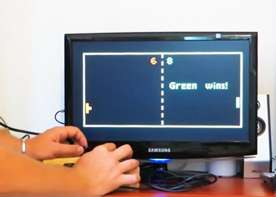
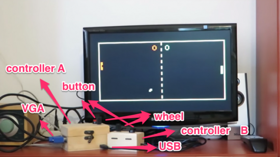
Everyone knows Pong, the first commercially successful arcade video game machine  originally release by Atari in 1972. In those years the game helped to establish the video game industry and nowadays is often used by makers to experiment with creating game consoles with Arduino.

Roberto Melzi recently shared on the Arduino forum a new version of Pong made with Arduino Uno:

Thanks to the VGAx library done by Smaffer, based on the previous work done by Nick Gammon, I have done a little color game for an Arduino Uno working for a VGA monitor. See for details here:

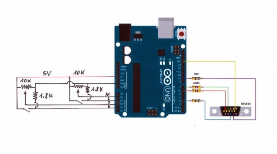
The target was to use an Arduino Uno board without special shields and supporting IC.
the fundamental components are a button, a potentiometer, few resistors and DSUB15 connector.

Tale a look at the video to see it in action:

Follow the step-by-step guide on Instructables to build one yourself.

Arduino Blog 24 Sep 21:11
arduino  featured  forum  library  pong  tutorial  uno  vga  video game  

A JTAG/XSVF Library for Arduino

Marcelo Jimenez developed a library to use an Arduino as a JTAG programmer. Basically a Python script uploads a XSVF file to an Arduino which interprets it and performs the necessary JTAG manipulation in order to do the programming.

The project is pretty simple because it just uses  a few resistors and some wires and the library is included in the Arduino library manager or you can check it  on Github.

He also wrote an article to explain some JTAG, SVF and XSVF basics:

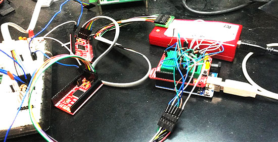
 I have recently felt the need to incorporate a JTAG port in a project to program a hardware that contained a CPLD. The idea was to both program it and perform some integrity tests on the board. I imagined something using pogo pins, to make it easier and quicker to test everything. I would also write the necessary test routines and generate some kind of report.

With this objective in mind, I have decided to design an Arduino shield to do the job. The testing routines were not really a big deal. And I was sure I would find some JTAG library for Arduino ready to be used. That was not the case.

There were some projects using Arduino to control a JTAG TAP (Test Access Port), but they were all incomplete. And I had no idea what was really JTAG. So I had to study a little bit to make things work for me.

In the end, the challenge proved enlightening. There were some caveats, both from hardware and from software. I’ll try to address them in this article.

Continue reading on his blog.

Arduino Blog 02 Sep 18:12
arduino  arduino uno  featured  jtag  library  uno  xsvf  

NeoPixel Heart Beat Display


Project Description


In this project, your heart will control a mesmerising LED sequence on a 5 metre Neopixel LED strip with a ws2812B chipset. Every heart beat will trigger a LED animation that will keep you captivated and attached to your Arduino for ages. The good thing about this project is that it is relatively easy to set up, and requires no soldering. The hardest part is downloading and installing the FastLED library into the Arduino IDE, but that in itself is not too difficult. The inspiration and idea behind this project came from Ali Murtaza, who wanted to know how to get an LED strip to pulse to his heart beat.
 
Have a look at the video below to see this project in action.


The Video


Parts Required:


Power Requirements

Before you start any LED strip project, the first thing you will need to think about is POWER. According to the Adafruit website, each individual NeoPixel LED can draw up to 60 milliamps at maximum brightness - white. Therefore the amount of current required for the entire strip will be way more than your Arduino can handle. If you try to power this LED strip directly from your Arduino, you run the risk of damaging not only your Arduino, but your USB port as well. The Arduino will be used to control the LED strip, but the LED strip will need to be powered by a separate power supply. The power supply you choose to use is important. It must provide the correct voltage, and must able to supply sufficient current.
 

Operating Voltage (5V)

The operating voltage of the NeoPixel strip is 5 volts DC. Excessive voltage will damage/destroy your NeoPixels.

Current requirements (9.0 Amps)

OpenLab recommend the use of a 5V 10A power supply. Having more Amps is OK, providing the output voltage is 5V DC. The LEDs will only draw as much current as they need. To calculate the amount of current this 5m strip can draw with all LEDs turned on at full brightness - white:

30 NeoPixel LEDs x 60mA x 5m = 9000mA = 9.0 Amps for a 5 metre strip.

Therefore a 5V 10A power supply would be able to handle the maximum current (9.0 Amps) demanded by a 5m NeoPixel strip containing a total of 150 LEDs.


Arduino Libraries and IDE


Before you start to hook up any components, upload the following sketch to the Arduino microcontroller. I am assuming that you already have the Arduino IDE installed on your computer. If not, the IDE can be downloaded from here.
 
The FastLED library is useful for simplifying the code for programming the NeoPixels. The latest "FastLED library" can be downloaded from here. I used FastLED library version 3.0.3 in this project.
 
If you have a different LED strip or your NeoPixels have a different chipset, make sure to change the relevant lines of code to accomodate your hardware. I would suggest you try out a few of the FastLED library examples before using the code below, so that you become more familiar with the library, and will be better equipped to make the necessary changes. If you have a 5 metre length of the NeoPixel 30 LED/m strip with the ws2812B chipset, then you will not have to make any modification below.
 

ARDUINO CODE:


1
2
3
4
5
6
7
8
9
10
11
12
13
14
15
16
17
18
19
20
21
22
23
24
25
26
27
28
29
30
31
32
33
34
35
36
37
38
39
40
41
42
43
44
45
46
47
48
49
50
51
52
53
54
55
56
57
58
59
60
61
62
63
64
65
66
67
68
69
70
71
72
73
74
75
76
77
78
79
80
81
82
83
84
85
86
87
88
89
90
91
92
93
94
95
96
97
98
99
100
101
102
103
104
105
106
107
108
109
110
111
112
113
114
115
116
117
118
119
120
121
122
123
124
125
126
127
128
129
130
131
132
133
134
135
136
137
138
139
140
/* ================================================================================================ Project: NeoPixel Heart Beat Display Neopixel chipset: ws2812B (30 LED/m strip) Author: Scott C Created: 8th July 2015 Arduino IDE: 1.6.4 Website: http://arduinobasics.blogspot.com/p/arduino-basics-projects-page.html Description: This sketch will display a heart beat on a 5m Neopixel LED strip. Requires a Grove Ear-clip heart rate sensor and a Neopixel strip. This project makes use of the FastLED library: http://fastled.io/ You may need to modify the code below to accomodate your specific LED strip. See the FastLED library site for more details. ================================================================================================== */ //This project needs the FastLED library - link in the description. #include "FastLED.h" //The total number of LEDs being used is 150 #define NUM_LEDS 150 // The data pin for the NeoPixel strip is connected to digital Pin 6 on the Arduino #define DATA_PIN 6 //Attach the Grove Ear-clip heart rate sensor to digital pin 2 on the Arduino. #define EAR_CLIP 2 //Initialise the LED array CRGB leds[NUM_LEDS]; //Initialise the global variables used to control the LED animation int ledNum = 0; //Keep track of the LEDs boolean beated = false; //Used to identify when the heart has beated int randomR = 0; //randomR used to randomise the fade-out of the LEDs //================================================================================================ // setup() : Is used to initialise the LED strip //================================================================================================ void setup() { FastLED.addLeds<NEOPIXEL,DATA_PIN>(leds, NUM_LEDS); //Set digital pin 2 (Ear-clip heart rate sensor) as an INPUT pinMode(EAR_CLIP, INPUT);} //================================================================================================ // loop() : Take readings from the Ear-clip sensor, and display the animation on the LED strip //================================================================================================ void loop() { //If the Ear-clip sensor moves from LOW to HIGH, call the beatTriggered method if(digitalRead(EAR_CLIP)>0){ //beatTriggered() is only called if the 'beated' variable is false. //This prevents multiple triggers from the same beat. ifbeated){ beatTriggered(); } } else { beated = false; //Change the 'beated' variable to false when the Ear-clip heart rate sensor is reading LOW. } //Fade the LEDs by 1 unit/cycle, when the heart is at 'rest' (i.e. between beats) fadeLEDs(5);} //================================================================================================ // beatTriggered() : This is the LED animation sequence when the heart beats //================================================================================================ void beatTriggered(){ //Ignite 30 LEDs with a red value between 0 to 255 for(int i = 0; i<30; i++){ //The red channel is randomised to a value between 0 to 255 leds[ledNum].r=random8(); FastLED.show(); //Call the fadeLEDs method after every 3rd LED is lit. if(ledNum%3==0){ fadeLEDs(5); } //Move to the next LED ledNum++; //Make sure to move back to the beginning if the animation falls off the end of the strip if(ledNum>(NUM_LEDS-1)){ ledNum=0; } } //Ignite 20 LEDS with a blue value between 0 to 120 for(int i = 0; i<20; i++){ //The blue channel is randomised to a value between 0 to 120 leds[ledNum].b=random8(120); FastLED.show(); //Call the fadeLEDs method after every 3rd LED is lit. if(ledNum%3==0){ fadeLEDs(5); } //Move to the next LED ledNum++; //Make sure to move back to the beginning if the animation falls off the end of the strip if(ledNum>(NUM_LEDS-1)){ ledNum=0; } } //Change the 'beated' variable to true, until the Ear-Clip sensor reads LOW. beated=true;} //================================================================================================ // fadeLEDs() : The fading effect of the LEDs when the Heart is resting (Ear-clip reads LOW) //================================================================================================ void fadeLEDs(int fadeVal){ for (int i = 0; i<NUM_LEDS; i++){ //Fade every LED by the fadeVal amount leds[i].fadeToBlackBy( fadeVal ); //Randomly re-fuel some of the LEDs that are currently lit (1% chance per cycle) //This enhances the twinkling effect. if(leds[i].r>10){ randomR = random8(100); if(randomR<1){ //Set the red channel to a value of 80 leds[i].r=80; //Increase the green channel to 20 - to add to the effect leds[i].g=20; } } } FastLED.show();}


NeoPixel Strip connection

The NeoPixel strip is rolled up when you first get it. You will notice that there are wires on both sides of the strip. This allows you to chain LED strips together to make longer strips. The more LEDs you have, the more current you will need. Connect your Arduino and power supply to the left side of the strip, with the arrows pointing to the right. (i.e. the side with the "female" jst connector).


NeoPixel Strip Wires

There are 5 wires that come pre-attached to either side of the LED strip.


You don't have to use ALL FIVE wires, however you will need at least one of each colour: red, white & green.


Fritzing sketch

The following diagram will show you how to wire everything together
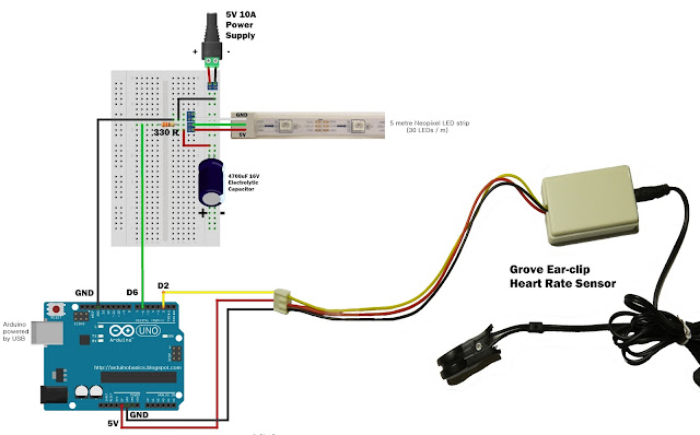
 
(click to enlarge)

Arduino Power considerations

Please note that the Arduino is powered by a USB cable.
If you plan to power the Arduino from your power supply, you will need to disconnect the USB cable from the Arduino FIRST, then connect a wire from the 5V line on the Power supply to the VIN pin on the Arduino. Do NOT connect the USB cable to the Arduino while the VIN wire is connected.


Large Capacitor

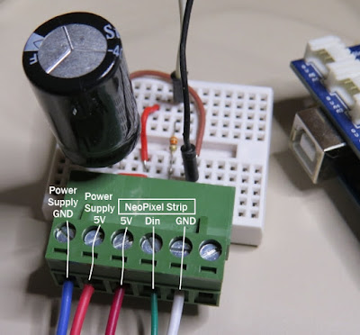
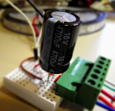
Adafruit also recommend the use of a large capacitor across the + and - terminals of the LED strip to "prevent the initial onrush of current from damaging the pixels". Adafruit recommends a capacitor that is 1000uF, 6.3V or higher. I used a 4700uF 16V Electrolytic Capacitor.


Resistor on Data Pin

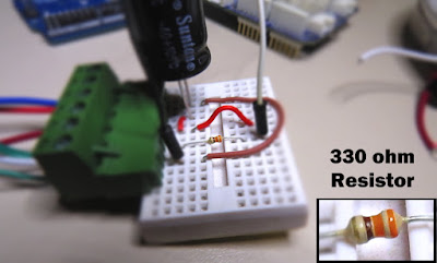
Another recommendation from Adafruit is to place a "300 to 500 Ohm resistor" between the Arduino's data pin and the data input on the first NeoPixel to prevent voltage spikes that can damage the first pixel. I used a 330 Ohm resistor.


Grove Ear-clip heart rate sensor connection

The Grove Base shield makes it easy to connect Grove modules to the Arduino. If you have a Grove Base shield, you will need to connect the Ear-clip heart rate sensor to Digital pin 2 as per the diagram below.


Completed construction

Once you have everything connected, you can plug the USB cable into the Arduino, and turn on the LED power supply. Attach the ear-clip to your ear (or to your finger) and allow a few seconds to allow the sensor to register your pulse. The LED strip will light up with every heart beat with an animation that moves from one end of the strip to the other in just three heart beats. When the ear-clip is not connected to your ear or finger, the LEDs should remain off. However, the ear clip may "trigger" a heart beat when opening or closing the clip.
 
Here is a picture of all the components (fully assembled).


Concluding comments


This very affordable LED strip allows you to create amazing animations over a greater distance. I thought that having less LEDs per metre would make the animations look "jittery", but I was wrong, they look amazing. One of the good things about this strip is the amount of space between each Neopixel, allowing you to easily cut and join the strip to the size and shape you need.
 
This LED strip is compatible with the FastLED library, which makes for easy LED animation programming. While I used this LED strip to display my heart beat, you could just as easily use it to display the output of any other sensor attached to the Arduino.


If you like this page, please do me a favour and show your appreciation :

 
Visit my ArduinoBasics Google + page.
Follow me on Twitter by looking for ScottC @ArduinoBasics.
I can also be found on Pinterest and Instagram.
Have a look at my videos on my YouTube channel.


This project would not have been possible without OpenLab's collaborative effort.
Please visit their site for more cool projects.


However, if you do not have a google profile...
Feel free to share this page with your friends in any way you see fit.
NeoPixel Heart Beat Display


Project Description


In this project, your heart will control a mesmerising LED sequence on a 5 metre Neopixel LED strip with a ws2812B chipset. Every heart beat will trigger a LED animation that will keep you captivated and attached to your Arduino for ages. The good thing about this project is that it is relatively easy to set up, and requires no soldering. The hardest part is downloading and installing the FastLED library into the Arduino IDE, but that in itself is not too difficult. The inspiration and idea behind this project came from Ali Murtaza, who wanted to know how to get an LED strip to pulse to his heart beat.
 
Have a look at the video below to see this project in action.


The Video


Parts Required:


Power Requirements

Before you start any LED strip project, the first thing you will need to think about is POWER. According to the Adafruit website, each individual NeoPixel LED can draw up to 60 milliamps at maximum brightness - white. Therefore the amount of current required for the entire strip will be way more than your Arduino can handle. If you try to power this LED strip directly from your Arduino, you run the risk of damaging not only your Arduino, but your USB port as well. The Arduino will be used to control the LED strip, but the LED strip will need to be powered by a separate power supply. The power supply you choose to use is important. It must provide the correct voltage, and must able to supply sufficient current.
 

Operating Voltage (5V)

The operating voltage of the NeoPixel strip is 5 volts DC. Excessive voltage will damage/destroy your NeoPixels.

Current requirements (9.0 Amps)

OpenLab recommend the use of a 5V 10A power supply. Having more Amps is OK, providing the output voltage is 5V DC. The LEDs will only draw as much current as they need. To calculate the amount of current this 5m strip can draw with all LEDs turned on at full brightness - white:

30 NeoPixel LEDs x 60mA x 5m = 9000mA = 9.0 Amps for a 5 metre strip.

Therefore a 5V 10A power supply would be able to handle the maximum current (9.0 Amps) demanded by a 5m NeoPixel strip containing a total of 150 LEDs.


Arduino Libraries and IDE


Before you start to hook up any components, upload the following sketch to the Arduino microcontroller. I am assuming that you already have the Arduino IDE installed on your computer. If not, the IDE can be downloaded from here.
 
The FastLED library is useful for simplifying the code for programming the NeoPixels. The latest "FastLED library" can be downloaded from here. I used FastLED library version 3.0.3 in this project.
 
If you have a different LED strip or your NeoPixels have a different chipset, make sure to change the relevant lines of code to accomodate your hardware. I would suggest you try out a few of the FastLED library examples before using the code below, so that you become more familiar with the library, and will be better equipped to make the necessary changes. If you have a 5 metre length of the NeoPixel 30 LED/m strip with the ws2812B chipset, then you will not have to make any modification below.
 

ARDUINO CODE:


1
2
3
4
5
6
7
8
9
10
11
12
13
14
15
16
17
18
19
20
21
22
23
24
25
26
27
28
29
30
31
32
33
34
35
36
37
38
39
40
41
42
43
44
45
46
47
48
49
50
51
52
53
54
55
56
57
58
59
60
61
62
63
64
65
66
67
68
69
70
71
72
73
74
75
76
77
78
79
80
81
82
83
84
85
86
87
88
89
90
91
92
93
94
95
96
97
98
99
100
101
102
103
104
105
106
107
108
109
110
111
112
113
114
115
116
117
118
119
120
121
122
123
124
125
126
127
128
129
130
131
132
133
134
135
136
137
138
139
140
/* ================================================================================================ Project: NeoPixel Heart Beat Display Neopixel chipset: ws2812B (30 LED/m strip) Author: Scott C Created: 8th July 2015 Arduino IDE: 1.6.4 Website: http://arduinobasics.blogspot.com/p/arduino-basics-projects-page.html Description: This sketch will display a heart beat on a 5m Neopixel LED strip. Requires a Grove Ear-clip heart rate sensor and a Neopixel strip. This project makes use of the FastLED library: http://fastled.io/ You may need to modify the code below to accomodate your specific LED strip. See the FastLED library site for more details. ================================================================================================== */ //This project needs the FastLED library - link in the description. #include "FastLED.h" //The total number of LEDs being used is 150 #define NUM_LEDS 150 // The data pin for the NeoPixel strip is connected to digital Pin 6 on the Arduino #define DATA_PIN 6 //Attach the Grove Ear-clip heart rate sensor to digital pin 2 on the Arduino. #define EAR_CLIP 2 //Initialise the LED array CRGB leds[NUM_LEDS]; //Initialise the global variables used to control the LED animation int ledNum = 0; //Keep track of the LEDs boolean beated = false; //Used to identify when the heart has beated int randomR = 0; //randomR used to randomise the fade-out of the LEDs //================================================================================================ // setup() : Is used to initialise the LED strip //================================================================================================ void setup() { FastLED.addLeds<NEOPIXEL,DATA_PIN>(leds, NUM_LEDS); //Set digital pin 2 (Ear-clip heart rate sensor) as an INPUT pinMode(EAR_CLIP, INPUT);} //================================================================================================ // loop() : Take readings from the Ear-clip sensor, and display the animation on the LED strip //================================================================================================ void loop() { //If the Ear-clip sensor moves from LOW to HIGH, call the beatTriggered method if(digitalRead(EAR_CLIP)>0){ //beatTriggered() is only called if the 'beated' variable is false. //This prevents multiple triggers from the same beat. ifbeated){ beatTriggered(); } } else { beated = false; //Change the 'beated' variable to false when the Ear-clip heart rate sensor is reading LOW. } //Fade the LEDs by 1 unit/cycle, when the heart is at 'rest' (i.e. between beats) fadeLEDs(5);} //================================================================================================ // beatTriggered() : This is the LED animation sequence when the heart beats //================================================================================================ void beatTriggered(){ //Ignite 30 LEDs with a red value between 0 to 255 for(int i = 0; i<30; i++){ //The red channel is randomised to a value between 0 to 255 leds[ledNum].r=random8(); FastLED.show(); //Call the fadeLEDs method after every 3rd LED is lit. if(ledNum%3==0){ fadeLEDs(5); } //Move to the next LED ledNum++; //Make sure to move back to the beginning if the animation falls off the end of the strip if(ledNum>(NUM_LEDS-1)){ ledNum=0; } } //Ignite 20 LEDS with a blue value between 0 to 120 for(int i = 0; i<20; i++){ //The blue channel is randomised to a value between 0 to 120 leds[ledNum].b=random8(120); FastLED.show(); //Call the fadeLEDs method after every 3rd LED is lit. if(ledNum%3==0){ fadeLEDs(5); } //Move to the next LED ledNum++; //Make sure to move back to the beginning if the animation falls off the end of the strip if(ledNum>(NUM_LEDS-1)){ ledNum=0; } } //Change the 'beated' variable to true, until the Ear-Clip sensor reads LOW. beated=true;} //================================================================================================ // fadeLEDs() : The fading effect of the LEDs when the Heart is resting (Ear-clip reads LOW) //================================================================================================ void fadeLEDs(int fadeVal){ for (int i = 0; i<NUM_LEDS; i++){ //Fade every LED by the fadeVal amount leds[i].fadeToBlackBy( fadeVal ); //Randomly re-fuel some of the LEDs that are currently lit (1% chance per cycle) //This enhances the twinkling effect. if(leds[i].r>10){ randomR = random8(100); if(randomR<1){ //Set the red channel to a value of 80 leds[i].r=80; //Increase the green channel to 20 - to add to the effect leds[i].g=20; } } } FastLED.show();}


NeoPixel Strip connection

The NeoPixel strip is rolled up when you first get it. You will notice that there are wires on both sides of the strip. This allows you to chain LED strips together to make longer strips. The more LEDs you have, the more current you will need. Connect your Arduino and power supply to the left side of the strip, with the arrows pointing to the right. (i.e. the side with the "female" jst connector).


NeoPixel Strip Wires

There are 5 wires that come pre-attached to either side of the LED strip.


You don't have to use ALL FIVE wires, however you will need at least one of each colour: red, white & green.


Fritzing sketch

The following diagram will show you how to wire everything together
 
(click to enlarge)

Arduino Power considerations

Please note that the Arduino is powered by a USB cable.
If you plan to power the Arduino from your power supply, you will need to disconnect the USB cable from the Arduino FIRST, then connect a wire from the 5V line on the Power supply to the 5V pin on the Arduino. Do NOT connect the USB cable to the Arduino while the 5V wire is connected to the Arduino.


Large Capacitor

Adafruit also recommend the use of a large capacitor across the + and - terminals of the LED strip to "prevent the initial onrush of current from damaging the pixels". Adafruit recommends a capacitor that is 1000uF, 6.3V or higher. I used a 4700uF 16V Electrolytic Capacitor.


Resistor on Data Pin

Another recommendation from Adafruit is to place a "300 to 500 Ohm resistor" between the Arduino's data pin and the data input on the first NeoPixel to prevent voltage spikes that can damage the first pixel. I used a 330 Ohm resistor.


Grove Ear-clip heart rate sensor connection

The Grove Base shield makes it easy to connect Grove modules to the Arduino. If you have a Grove Base shield, you will need to connect the Ear-clip heart rate sensor to Digital pin 2 as per the diagram below.


Completed construction

Once you have everything connected, you can plug the USB cable into the Arduino, and turn on the LED power supply. Attach the ear-clip to your ear (or to your finger) and allow a few seconds to allow the sensor to register your pulse. The LED strip will light up with every heart beat with an animation that moves from one end of the strip to the other in just three heart beats. When the ear-clip is not connected to your ear or finger, the LEDs should remain off. However, the ear clip may "trigger" a heart beat when opening or closing the clip.
 
Here is a picture of all the components (fully assembled).


Concluding comments


This very affordable LED strip allows you to create amazing animations over a greater distance. I thought that having less LEDs per metre would make the animations look "jittery", but I was wrong, they look amazing. One of the good things about this strip is the amount of space between each Neopixel, allowing you to easily cut and join the strip to the size and shape you need.
 
This LED strip is compatible with the FastLED library, which makes for easy LED animation programming. While I used this LED strip to display my heart beat, you could just as easily use it to display the output of any other sensor attached to the Arduino.


If you like this page, please do me a favour and show your appreciation :

 
Visit my ArduinoBasics Google + page.
Follow me on Twitter by looking for ScottC @ArduinoBasics.
I can also be found on Pinterest and Instagram.
Have a look at my videos on my YouTube channel.


This project would not have been possible without OpenLab's collaborative effort.
Please visit their site for more cool projects.


However, if you do not have a google profile...
Feel free to share this page with your friends in any way you see fit.
A Simple Floppy Music Controller

While playing music with floppy drives has been done many times over, making any device with a stepper motor play music still appeals to the hacker in all of us. [Tyler] designed an Arduino shield and a library which lets you get up and running in no time. [Tyler]‘s shield includes pin headers to connect 4 floppy drives, which plug directly into the shield. The drives don’t need any modification before being used.

While you could simply wire a few floppy drives up to an Arduino with some jumpers, this breakout shield makes connecting your drives trivial. In addition to designing the shield, [Tyler] released an Arduino library to make things even easier. The library lets you simply set the frequency you want each drive to play, which saves a bit of legwork.

The floppy-controlling Arduino library is available on GitHub and a video of the controller is included after the break.


Filed under: musical hacks
Hack a Day 12 Oct 12:00

Reverse Engineering a Wireless Studio Lighting Remote

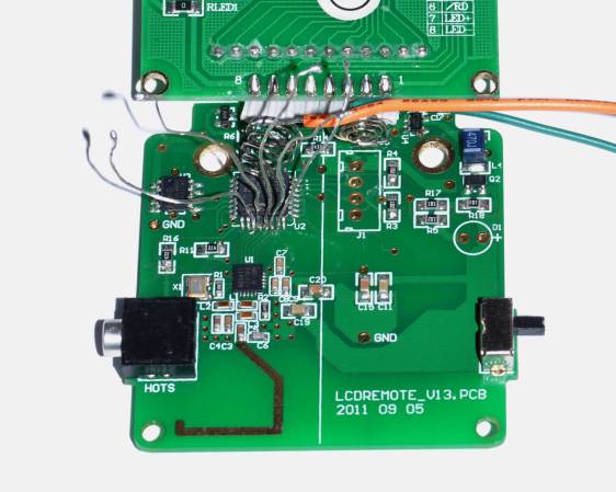
If you want to take a photograph with a professional look, proper lighting is going to be critical. [Richard] has been using a commercial lighting solution in his studio. His Lencarta UltraPro 300 studio strobes provide adequate lighting and also have the ability to have various settings adjusted remotely. A single remote can control different lights setting each to its own parameters. [Richard] likes to automate as much as possible in his studio, so he thought that maybe he would be able to reverse engineer the remote control so he can more easily control his lighting.

[Richard] started by opening up the remote and taking a look at the radio circuitry. He discovered the circuit uses a nRF24L01+ chip. He had previously picked up a couple of these on eBay, so his first thought was to just promiscuously snoop on the communications over the air. Unfortunately the chips can only listen in on up to six addresses at a time, and with a 40-bit address, this approach may have taken a while.

Not one to give up easily, [Richard] chose a new method of attack. First, he knew that the radio chip communicates to a master microcontroller via SPI. Second, he knew that the radio chip had no built-in memory. Therefore, the microcontroller must save the address in its own memory and then send it to the radio chip via the SPI bus. [Richard] figured if he could snoop on the SPI bus, he could find the address of the remote. With that information, he would be able to build another radio circuit to listen in over the air.

Using an Open Logic Sniffer, [Richard] was able to capture some of the SPI communications. Then, using the datasheet as a reference, he was able to isolate the communications that stored information int the radio chip’s address register. This same technique was used to decipher the radio channel. There was a bit more trial and error involved, as [Richard] later discovered that there were a few other important registers. He also discovered that the remote changed the address when actually transmitting data, so he had to update his receiver code to reflect this.

The receiver was built using another nRF24L01+ chip and an Arduino. Once the address and other registers were configured properly, [Richard's] custom radio was able to pick up the radio commands being sent from the lighting remote. All [Richard] had to do at this point was press each button and record the communications data which resulted. The Arduino code for the receiver is available on the project page.

[Richard] took it an extra step and wrote his own library to talk to the flashes. He has made his library available on github for anyone who is interested.


Filed under: Arduino Hacks, radio hacks

Arduino SPI Library Gains Transaction Support

Transaction SPI Timing

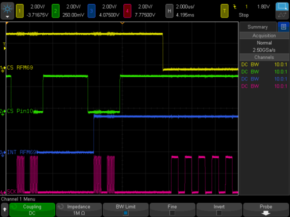
To prevent data corruption when using multiple SPI devices on the same bus, care must be taken to ensure that they are only accessed from within the main loop, or from the interrupt routine, never both. Data corruption can happen when one device is chip selected in the main loop, and then during that transfer an interrupt occurs, chip selecting another device. The original device now gets incorrect data.

For the last several weeks, [Paul] has been working on a new Arduino SPI library, to solve these types of conflicts. In the above scenario, the new library will generate a blocking SPI transaction, thus allowing the first main loop SPI transfer to complete, before attempting the second transfer. This is illustrated in the picture above, the blue trace rising edge is when the interrupt occurred, during the green trace chip select. The best part, it only affects SPI, your other interrupts will still happen on time. No servo jitter!

This is just one of the new library features, check out the link above for the rest. [Paul] sums it up best: “protects your SPI access from other interrupt-based libraries, and guarantees correct setting while you use the SPI bus”.


Filed under: Arduino Hacks
Hack a Day 01 Aug 21:01

Need Help with conflicting Arduino libraries

Hello everyone,

I recently recieved some HC-SR04's and am wanting to make a little device to test them. The idea is that one sensor controls when a piezo buzzer will play, and the other sensor will decide the pitch of that note. I have written some code together but on trying to compile I get this error:


core.a(Tone.cpp.o): In function `__vector_7':

C:\Program Files (x86)\arduino-1.0.1\hardware\arduino\cores\arduino/Tone.cpp:523: multiple definition of `__vector_7'

read more

Let's Make Robots 05 Dec 01:35
arduino  avr  conflict  help  library  newping  tone  

Converting an STL file to Gcode to drive a CNC mill or lathe

As mentioned in my blog, "Multipurpose Mini Machine" DAGU wants to develop a low cost CNC machine kit. The models shown here will not be the final product, they are simply what I used for testing the quality of the components.

Part of the kit will be an Arduino compatible controller. Ok, I know, nothing new so far.

read more

Let's Make Robots 04 Nov 09:20
arduino  card  cnc  dagu  gcode  library  programming  sd  stl  

DSS Circuits - bringing SMD to DIY

This is a cool site with some interesting PCB's including an I2C GPS Arduino sheild. The owner of the site, Wayne Truchsess has also written a great I2C library that I am using now.

Check out his open source tracking device that featured on Kickstarter here: http://www.kickstarter.com/projects/dsscircuits/open-source-tracking-device

read more

Let's Make Robots 18 Sep 06:52
arduino  gps  i2c  library  pcb  robot  shield  shops  smd