Posts with «led hacks» label

540 LEDs On A Geodesic Sphere

[burgerga] loves attending Music Festivals. He’s also a MechE who loves his LED’s. He figured he needed to put it all together and do something insane, so he build a huge, 15″ geodesic sphere containing 540 WS2812B addressable LED’s. He calls it the SOL CRUSHER. It sips 150W when all LED’s are at full intensity, making it very, very, bright.

As with most WS2812B based projects, this one too is fairly straightforward, electrically. It’s controlled by four Teensy 3.2 boards mounted on Octo WS2811 adapter boards. Four 10,000 mAh 22.2V LiPo batteries provide power, which is routed through a 5V, 30Amp heatsinked DC-DC converter. To protect his LiPo batteries from over discharge, he built four voltage monitoring modules. Each had a TC54 voltage detector and an N-channel MOSFET which switches off the LiPo before its voltage dips below 3V. He bundled in a fuse and an indicator, and put each one in a neat 3D printed enclosure.

The mechanical design is pretty polished. Each of the 180 basic modules is a triangular PCB with three WS2812B’s, filter capacitors, and heavy copper pours for power connections. The PCB’s are assembled in panels of six and five units each, which are then put together in two hemispheres to form the whole sphere. His first round of six prototypes set him back as he made a mistake in the LED footprint. But it still let him check out the assembly and power connections. For mechanical support, he designed an internal skeleton that could be 3D printed. There’s a mounting frame for each of the PCB panels and a two piece central sphere. Fibreglass rods connect the central sphere to each of the PCB panels. This lets the whole assembly be split in to two halves easily.

It took him over six months and lots of cash to complete the project. But the assembly is all done now and electrically tested. Next up, he’s working on software to add animations. He’s received suggestions to add sensors such as microphones and accelerometers via comments on Reddit. If you’d like to help him by contributing animation suggestions, he’s setup a Readme document on Dropbox, and a Submission form. Checkout the SolCrusher website for more information.

Thanks [Vinny Cordeiro], for letting us know about this build.


Filed under: led hacks
Hack a Day 12 Jun 12:00

Banish Dangerous Shadows Under Kitchen Cabinets

[nebulous] has a lot of problems with his kitchen cabinets. Aside from a noted lack of micro-controllers, he was especially suspicious of the dark spaces under them. Anything could be hiding there.

The core of the project is a $10 Arduino-compatible esp8266 board from digistump. The board is powered by the five volt regulator of an L298N motor driver module hooked to a power-supply. All this controls a set-of LED strips adhered to the underside of the cabinets with the traditionally bad adhesive strips with which they come standard. We can predict an hour spent bent awkwardly cursing at them, a hot-glue gun in one hand, in [nebulous]’s future. The whole set-up is housed in a SparkFun cardboard box above the microwave. You can barely tell it’s not a commercial product.

We’re not certain if we like a future where even our cabinetry has an IP address. However, this is a good weekend project that could make all our cabinetry brighter, safer, and more connected.


Filed under: home hacks, led hacks

The Flowing Pixels of Time Wait for No Man

The hourglass dramatically depicts the flow of time; gravity pulling grains of sand inevitably downward. So it is with the Bits of Time project by [Frank Andre]. The pixels drop, stopping only when the battery dies. Or, when your eggs are ready. (Pssst, it’s also on Hackaday.io.)

Look, Ma! No GIF!

The project starts with a couple of [Frank’s] PixBlocks. A processor is added to one PixBlock to serve as the controller for both after they are connected via the serial bus. A tilt switch, with a debouncing circuit, is connected to an IO pin. This tells the processor the orientation of the box and therefore which way the pixels should flow.

Two  switches set the duration of the timer in 15 second increments. A third starts the timer. When the box is rotated the pixels start flowing in the opposite direction. With code available on GitHub the system can be programmed for other effects such as changing colors, flickering, or even text display.

You’ll agree this is a bit less intimidating than the MacGyver-ish kitchen timer we covered last year.


Filed under: clock hacks, led hacks

Swimming Pool Dance Floor Enlightened With Leds

In a well documented blog entry, [Loren Bufanu] presents a project that lit up a glass dance floor covering a swimming pool with RGB strips. We mentioned a video of his project in a Hackaday links but didn’t have any background information. Now we do.

The project took around 450 meters of RGB strips controlled by two Rainbowduinos and driven by sixty-four power Mosfets, sixty-four bipolar transistors, and a few other components. Running just the white LEDs draws 8 amps of power.
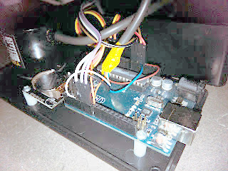
The Rainbowduino is an ATmega328 Arduino compatible board with two MY9221 controllers. Each  controller handles 12 channels of Adaptive Pulse Density Modulation. In other words, it makes the LEDs flash nicely. [Loren] used the Rainbowduino instead of some alternatives because multiple R’duinos can coordinate their activities over I2C.

The software part of the project did not work as well as the hardware. The light patterns were supposed to follow the music being played. A PC software package intended to drive the R’duinos produced just a muddy mess. Some kludges, including screen captures (!), driven by a batch file tamed the unruliness.

It’s been awhile, but a similar disco dance floor, built by [Chris Williamson] but not over a pool, previously caught our attention. [Chris] is a principle in Terror Tech that recently got a mention on Sparkfun.

The video after the break fortunately does not make a big splash, but is still electrifying.


Filed under: Arduino Hacks, led hacks

LED Pendulum Pulses Out Clock Face

You have to admit [Dylan Rush’s] clock is a real swinger. Literally. You’ve seen the desk novelties where an arm with leds mounted on it sweeps out a message? [Dylan] did the same thing to make a clock but instead of drawing numbers, he actually draws an analog clock face. Y’know one of those round things with arms?

Behind the clock is an Arduino driving a MAX7219 LED controller. Using the MAX7219 was a challenge because it expects a grid of LEDs while the clock needs a linear array. [Dylan] used a line of individual LEDs wired to match what the controller wanted. A rotary encoder tells the processor the position of the arm so the Arduino sketch can determine which LEDs should be lit to show the time and clock face.

What’s even more amazing is [Dylan] created this before clocks became infamous.

Swing over to the video after the break.


Filed under: Arduino Hacks, clock hacks, led hacks

“Arduino Borealis” Combines LEDs and Paint

[Stef Cohen] decided to combine three different artistic mediums for her latest project. Those are painting, electronics, and software. The end goal was to recreate the aurora borealis, also known as the northern lights, in a painting.

The first step was to make the painting. [Stef] began with a shadow box. A shadow box is sort of like a picture frame that is extra deep. A snowy scene was painted directly onto the front side of the glass plate of the shadow box using acrylic paint. [Stef] painted the white, snowy ground along with some pine trees. The sky was left unpainted, in order to allow light to shine through from inside of the shadow box. A sheet of vellum paper was fixed to the inside of the glass pane. This serves to diffuse the light from the LEDs that would eventually be placed inside the box.

Next it was time to install the electronics. [Stef] used an off-the-shelf RGB LED matrix from Adafruit. The matrix is configured with 16 rows of 32 LEDs each. This was controlled with an Arduino Uno. The LED matrix was mounted inside the shadow box, behind the vellum paper. The Arduino code was easily written using Adafruit’s RGB Matrix Panel library.

To get the aurora effect just right, [Stef] used a clever trick. She took real world photographs of the aurora and pixelated them using Photoshop. She could then sample the color of each pixel to ensure that each LED was the appropriate color. Various functions from the Adafruit library were used to digitally paint the aurora into the LED matrix. Some subtle animations were also included to give it an extra kick.


Filed under: Arduino Hacks, led hacks

An Introduction To Individually Addressable LED Matrices

The most fascinating project you can build is something with a bunch of blinky hypnotic LEDs, and the easiest way to build this is with a bunch of individually addressable RGB LEDs. [Ole] has a great introduction to driving RGB LED matrices using only five data pins on a microcontroller.

The one thing that is most often forgotten in a project involving gigantic matrices of RGB LEDs is how to mount them. The enclosure for these LEDs should probably be light and non-conductive. If you’re really clever, each individual LED should be in a light-proof box with a translucent cover on it. [Ole] isn’t doing that here; this matrix is just a bit of wood with some WS2812s glued down to it.

To drive the LEDs, [Ole] is using an Arduino. Even though the WS2812s are individually addressable and only one data pin is needed, [Ole] is using five individual data lines for this matrix. It works okay, and the entire setup can be changed at some point in the future. It’s still a great introduction to individually addressable LED matrices.

If you’d like to see what can be done with a whole bunch of individually addressable LEDs, here’s the FLED that will probably be at our LA meetup in two weeks. There are some crazy engineering challenges and several pounds of solder in the FLED. For the writeup on that, here you go.


Filed under: Arduino Hacks, led hacks
Hack a Day 27 Apr 06:00

Arduino Tetris on a Multiplexed LED Matrix

[Alex] needed a project for his microcomputer circuits class. He wanted something that would challenge him on both the electronics side of things, as well as the programming side. He ended up designing an 8 by 16 grid of LED’s that was turned into a game of Tetris.

He arranged all 128 LED’s into the grid on a piece of perfboard. All of the anodes were bent over and connected together into rows of 8 LED’s. The cathodes were bent perpendicularly and forms columns of 16 LED’s. This way, if power is applied to one row and a single column is grounded, one LED will light up at the intersection. This method only works reliably to light up a single LED at a time. With that in mind, [Alex] needed to have a very high “refresh rate” for his display. He only ever lights up one LED at a time, but he scans through the 128 LED’s so fast that persistence of vision prevents you from noticing. To the human eye, it looks like multiple LED’s are lit up simultaneously.

[Alex] planned to use an Arduino to control this display, but it doesn’t have enough outputs on its own to control all of those lights. He ended up using multiple 74138 decoder/multiplexer IC’s to control the LED’s. Since the columns have inverted outputs, he couldn’t just hook them straight up to the LED’s. Instead he had to run the signals through a set of PNP transistors to flip the logic. This setup allowed [Alex] to control all 128 LED’s with just seven bits, but it was too slow for him.

His solution was to control the multiplexers with counter IC’s. The Arduino can just increment the counter up to the appropriate LED. The Arduino then controls the state of the LED using the active high enable line from the column multiplexer chip.

[Alex] wanted more than just a static image to show off on his new display, so he programmed in a version of Tetris. The controller is just a piece of perfboard with four push buttons. He had to work out all of the programming to ensure the game ran smoothly while properly updating the screen and simultaneously reading the controller for new input. All of this ran on the Arduino.

Can’t get enough Tetris hacks? Try these on for size.


Filed under: Arduino Hacks, led hacks

LED Matrix Infinity Mirror

[Evan] wrote in to let us know about the LED matrix infinity mirror he’s been working on. [Evan] built a sizable LED matrix out of WS2812B LEDs and mounted them to a semi-reflective acrylic sheet, which makes a pretty awesome infinity mirror effect.

Instead of buying pre-wired strands of serial LEDs like we’ve seen in some other projects, [Evan] purchased individual WS2812 LEDs in bulk. Since the LEDs just had bare leads, [Evan] had to solder wires between each of his 169 LEDs (with some help from a few friends). After soldering up hundreds of wires, [Evan] drilled out holes for each LED in a piece of semi-reflective acrylic and inserted an LED into each hole.

To create the infinity mirror effect, [Evan] mounted the LED matrix behind a window. [Evan] put some one-way mirror film on the outside of the window, which works with the semi-reflective acrylic to create the infinity mirror effect. The LEDs are driven by an Arduino, which is controlled by a couple of free programs to show a live EQ of [Evan]’s music along with patterns and other effects.


Filed under: led hacks

Binary Clock Fit For Queen Elsa’s Ice palace

When life gives you lemons, you make lemonade. When life gives you freezing cold temperatures and a yard full of snow, you make binary clocks out of ice. At least that’s what [Dennis] does, anyway.

[Dennis’] clock is made from several cylindrical blocks of ice stacked on top of one another. There are six columns of ice blocks. The blocks were made by pouring water into empty margarine containers and freezing them. Once they were frozen, [Dennis] bore a 5/16″ hole into the bottom of each block to house an LED. Wires ran from the LEDs back into the drainage port of a cooler.

The cooler housed the main electronics. The LED controller board is of [Dennis’] own design. It contains six TLC59282 chips allowing for control of up to 96 LEDs. Each chip has its output lines running to two RJ45 connectors. [Dennis] couldn’t just use one because one of the eight wires in the connector was used as a common power line. The main CPU is an Arduino. It’s hooked up to a DS3234 Real Time Clock in order to keep accurate time. The oscillator monitors temperature in order to keep accurate time even in the dead of winter.


Filed under: Arduino Hacks, led hacks