In Newton’s measurement of g, I described a failed experiment to measure g with a motorized circular pendulum. Further experimentation on my own lead me to adopt for this week’s lab the standard approach using an unpowered circular pendulum. The cone formed by the string can be described as having height  , base radius
  , and hypotenuse
  , the length of the string. If the circular pendulum has period
  , then
  (derived in the Newton post). If we make the string long and push the pendulum with the right speed to get a nearly circular (rather than elliptical) motion, then
 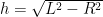 is nearly constant for many orbits, and we can estimate the period with just a stopwatch by counting 20 or 30 periods. Using a large enough mass means that neglecting air resistance is now reasonable (which it was not for the tiny mass I started with).
Thanks to John Burk for suggesting that I forget about the motor—that seems to be the best approach, even though I then can’t use the photogate to time the period. I’m hopeful that we can measure the height and the period accurately enough to get within about 2% of the right value for  .
.
This week in addition to doing the circular pendulum right, I wanted to do simple pendulums. I’ve assigned problem 4.P.89 in Matter and Interactions, which seems to be the only place in the book that simple pendulums are done. It is a computational problem, since there isn’t an analytic solution (though the small-angle approximation works pretty well up to about 45°). I hope the students have done that by tomorrow!
I wanted to measure the period of the pendulum directly (not averaging over many periods), to demonstrate that the amplitude does not matter much. Unfortunately, I’ve not yet built a sensor that works for this. I tried using the photogate, but I could not hit the 1 cm gap consistently, even with a shorter pendulum.
I also tried using a magnetic sensor (using the circuit I used for the speed-of-sound lab) with a magnet for the pendulum weight, but that triggered at random times as the magnet came close. Even 20cm away the field was enough to trigger the detector, and I got almost random timings. A magnetometer was no better than the coil and comparator, as the magnetic field varied chaotically (from movements of the magnet other than the simple pendulum swing, such as twirling on the string). The magnetometer was usable as a compass, though, which is good, because I originally bought it for the robotics club to use as a compass. There are some tricky points to using it as a compass, which I’ll talk about in a different post.
I then tried marking the top of the string with a bit of electrical tape and using the photogate there. That was the most successful so far—if I hold the photogate steady enough, I can get readings repeatable to ±20msec, which is much better than I can do with any other approach I’ve tried. For one pendulum hanging from the edge of my desk, I either got two pulses at about 1.11 and 0.45 seconds or one pulse every 1.56 seconds, depending on whether the marker on the string passes all the way through the beam or blocks it continuously at the end of the swing. The random variation I get is probably because of holding the sensor by hand (to align with the string).
If I had a more rigid way to mount the sensor, I should be able get more consistent readings, so my main engineering task was to get a rigid pivot point on the ceiling beam (without making any holes) and mount the photogate in a rigid, but adjustable, way. Of my two standard mechanical engineering techniques, duct tape and Lego, I chose Lego:

A view of the photogate mounted on the Lego beam next to the pendulum string.

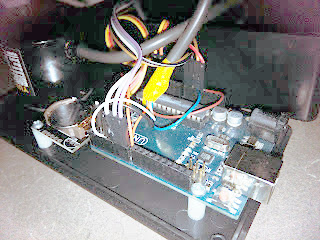
Closeup of the photogate, showing the breakout board and sensor wedged between a plate and a beam, with a 2-plate spacer.
Having come up with a nice way to grip the photogate and still be able to swing a pendulum string into the gap, I connected the beam holding the photogate to the same right-angle platform that we had used last week for the motorized pendulum. This left a little gap that I could rest the Arduino board in, so that there was no tension on the wires to the photogate.
I was a bit worried that I might have to put my laptop on top of a ladder, since the USB cord is not very long, but I have a spare pair of USB-to-Cat5 converters (one set is for the robotics project), so I was able to make an extension cord out of a flexible Cat-5 Ethernet cable, giving me enough length to put my laptop safely on the desk.

The same Lego that holds the photogate can also support the Arduino, so I don't need to hold anything in my hands.
I had two other ideas I haven’t tried: using one of the ultrasonic range finders to track the pendulum motion and using a video camera to time the motion. These require interpolation of position data to estimate the period, so I’d rather avoid them for now. The top-of-string photogate will work (I think) for the simple pendulum, and the circular pendulum can be timed with a stopwatch averaged over many periods. (I could even use the photogate timer as a stopwatch, though the resolution of the stop watch on my Casio wristwatch is 0.01 seconds, and human reflexes make anything less than 0.1 second pretty much noise.)
Tagged:
AP physics,
Arduino,
circular pendulum,
g,
gravity,
high school,
Lego,
Newton,
pendulum,
photogate,
physics 


 Behind the clock is an Arduino driving a MAX7219 LED controller. Using the MAX7219 was a challenge because it expects a grid of LEDs while the clock needs a linear array. [Dylan] used a line of individual LEDs wired to match what the controller wanted. A rotary encoder tells the processor the position of the arm so the Arduino sketch can determine which LEDs should be lit to show the time and clock face.

 , then measured both circular and simple pendulums. For the circular pendulum we measured the radius of the cone on the first orbit and the last orbit, the length of the string (the slant height of the cone), and approximated the period by timing 10 or 20 periods and dividing. For the simple pendulum, we used the photogate setup described in


