IKEA’s products are known for their clean, Scandinavian design and low cost, but it is their DIY or “assemble it yourself” feature that probably makes them so popular with hackers. We seem to receive tips about IKEA hacks with a consistent regularity. [Robin Reiter] has a Bekant Sit/Stand motorized table with buttons to raise and lower the surface, but it doesn’t have any memory presets. That’s a shame because it requires a lot of fiddling with the up/down buttons to get it right every time. It would be nice to press a button, go grab a Coffee, and come back to find it adjusted at the desired height. With a little bit of hacking, he was able to not only add memory preset buttons, but also a USB interface for future computer control.
The existing hardware consists of a PIC16LF1938 micro-controller with two buttons for movement control and a LIN bus protocol which communicates with the automotive grade motors with integrated encoders that report position values. After a bit of sniffing around with his oscilloscope and analyzer, he was able to figure out the control codes for the motor movements. For some strange reason, however, the LIN signals were inverted, so he had to introduce a transistor signal inverter between the PIC master and the Arduino Nano that would act as a slave LIN node. Software was made much easier thanks to an Arduino library developed by [Zapta] for the LIN Bus signal Injector, The controls now have four buttons — two to replicate the original up/down movements, and the other two to act as memory presets.
The code, schematic and a simple wiring layout are posted on Github, in case there are others out there who’d like to replicate this hack. Check out the video after the break where he gives a walk through the code.
When teaching Industrial Automation to students, you need to give them access to the things they will encounter in industry. Most subjects can be taught using computer programs or simulators — for example topics covering PLC, DCS, SCADA or HMI. But to teach many other concepts, you need to have the actual hardware on hand to be able to understand the basics. For example, machine vision, conveyor belts, motor speed control, safety and interlock systems, sensors and peripherals all interface with the mentioned control systems and can be better understood by having hardware to play with. The team at [Absolutelyautomation] have published several projects that aim to help with this. One of these is the DIY conveyor belt with a motor speed control and display.
This is more of an initial, proof of concept project, and there is a lot of room for improvement. The build itself is straightforward. All the parts are standard, off the shelf items — stuff you can find in any store selling 3D printer parts. A few simple tools is all that’s required to put it together. The only tricky part of the build would likely be the conveyor belt itself. [Absolutelyautomation] offers a few suggestions, mentioning old car or truck tyres and elastic resistance bands used for therapy / exercise as options.
If you plan to replicate this, a few changes would be recommended. The 8 mm rollers could do with larger “drums” over them — about an inch or two in diameter. That helps prevent belt slippage and improves tension adjustment. It ought to be easy to 3D print the add-on drums. The belt might also need support plates between the rollers to prevent sag. The speed display needs to be in linear units — feet per minute or meters per minute, rather than motor rpm. And while the electronics includes a RS-485 interface, it would help to add RS-232, RS-422 and Ethernet in the mix.
While this is a simple build, it can form the basis for a series of add-ons and extensions to help students learn more about automation and control systems. Or maybe you want a conveyor belt in your basement, for some reason.
Remember that feeling when you first looked down on a microscope? Now you can re-live it but in slightly different way. [Venkes] came up with a way to make a Laser Scanning Microscope (LSM) with mostly off the shelf components that you probably have sitting around, collecting dust in your garage. He did it using some modified DVD pick-ups, an Arduino Uno, a laser and a LDR.
EPROM die shot
To be honest, there’s some more stuff involved in the making of the LSM but [Venkes] did a detailed Instructable explaining how everything fits together. You will need a fair dose of patience, it’s not very easy to get the focus right and it’s quite slow, an image takes about half an hour to complete, but it can do 1300x amplification at 65k pixels (256×256). From reading the instructions it seems that you will need a steady hand to assemble it together, some steps look kind of tricky. On the software side, the LSM uses Arduino and Processing. The Arduino part is responsible for the steering of the lens and taking the LDR readings. This information is then sent to Processing which takes care of interpreting the data and translate it to an image.
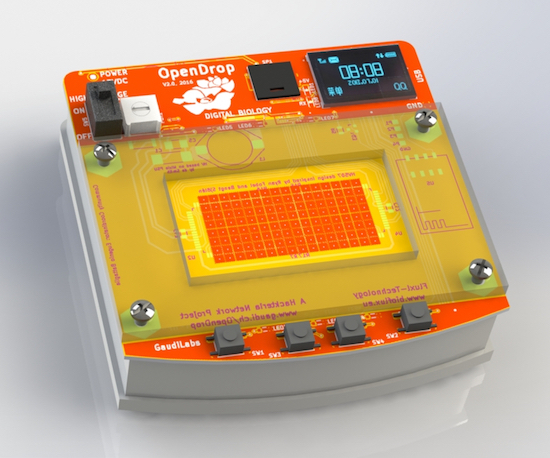
OpenDrop V2 is an updated design for an open-source digital microfludics platform, which was initiated by GaudiLabs in Luzern, Switzerland and developed by several communities including hackteria | open source biological art, BioFlux and digi.bio. The device is part of a much larger ecosystem focused around digital biology with hopes of making personal lab automation accessible to more people.
OpenDrop runs on a new technology called “electro-wetting” to control small droplets of liquids, which allows anyone to carry out digital biology experiments. Potential applications are not only limited to science, but the art, music, gaming and education fields as well.
One such example is OpenDropper, an 8-bit video game based on the OpenDrop. You can see it below!
Finding a product that is everything you want isn’t always possible. Making your own that checks off all those boxes can be. [Peter Clough] took the latter route and built a small Bluetooth speaker with an LED visualization display that he calls Magic Box.
A beefy 20W, 4Ohm speaker was screwed to the lid of a wooden box converted to the purpose. [Clough] cut a clear plastic sheet to the dimensions of the box, notching it 2cm from the edge to glue what would become the sound reactive neopixel strip into place — made possible by an electret microphone amplifier. There ended up being plenty of room inside the speaker box to cram an Arduino Pro Mini 3.3V, the RN-52 Bluetooth receiver, and the rest of the components, with an aux cable running out the base of the speaker. As a neat touch, neodymium magnets hold the lid closed.
We gotta say, a custom speaker with LED visualization makes for a tidy little package — aside from the satisfaction that comes from building it yourself.
High-altitude ballooning is becoming a popular activity for many universities, schools and hacker spaces. The balloons, which can climb up to 40 km in the stratosphere, usually have recovery parachutes to help get the payload, with its precious data, back to solid ground safely. But when you live in areas where the balloon is likely to be flying over the sea most of the time, recovery of the payload becomes tricky business. [Paul Clark] and his team from Durham University’s Centre for Advanced Instrumentation are working on building a small, autonomous glider – essentially a flying hard drive – to navigate from 30 km up in the stratosphere to a drop zone somewhere near a major road. An important element of such a system is the locator beacon to help find it. They have now shared their design for an “Iridium 9603 Beacon” — a small Arduino-compatible unit which can transmit its location and other data from anywhere via the Iridium satellite network.
The beacon uses the Short Burst Data service which sends email to a designated mail box with its date, time, location, altitude, speed, heading, temperature, pressure and battery voltage. To do all of this, it incorporates a SAMD21G18 M0 processor; FGPMMOPA6H GPS module; MPL3115A2 altitude sensor; Iridium 9603 Short Burst Data module + antenna and an LTC3225 supercapacitor charger. Including the batteries and antenna, the whole thing weighs in at 72.6 g, making it perfectly suited for high altitude ballooning. The whole package is powered by three ‘AAA’ Energizer Ultimate Lithium batteries which ought to be able to withstand the -56° C encountered during the flight. The supercapacitors are required to provide the high current needed when the beacon transmits data.
The team have tested individual components up to 35 km on a balloon flight from NASA’s Columbia Scientific Balloon Facility and the first production unit will be flown on a much smaller balloon, launched from the UK around Christmas. The GitHub repository contains detailed information about the project along with the EagleCAD hardware files and the Arduino code. Now, if only Santa carried this on his Sleigh, it would be easy for NORAD to track his progress in real time.
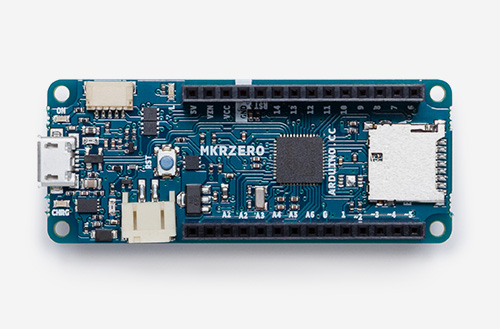
Say hello to the newest member of the Arduino family! The MKRZero–now available on our stores at the price of $21.90/€20.90 (+ tax)–shrinks the functionality of the Arduino Zero down into an Arduino MKR1000 form factor, making it a great educational tool for learning about 32-bit application development.
Like the Zero, the latest board is based on a Microchip SAM D21 ARM Cortex®-M0+ MCU. An integrated SD connector with dedicated SPI interfaces (SPI1) allows you to play with files without any extra hardware, while an analog converter enables you to monitor its battery voltage.
The MKRZero’s features in a nutshell:
small form factor
number crunching capability
low power consumption
integrated battery management
USB host
integrated SD management
programmable SPI, I2C and UART
Interested? You can explore the MKRZero in more detail, including its technical documentation, via the links below:
If you use the Arduino IDE, you will need to add the new Intel SAMD Core, selecting Tools menu, then Boards, and last Boards Manager on the Arduino Software (IDE).
Watch out music makers, we’ve got some news for you! We have released two libraries for your enjoyment:
Arduino Sound library – a simple way to play and analyze audio data using Arduino on SAM D21-based boards.
I2S library – to use the I2S protocol on SAMD21-based boards. For those who don’t know, I2S (Inter-IC Sound) is an electrical serial bus interface standard for connecting digital audio devices.
This robust DIN-rail mountable, Leonardo-compatible controller enables you to take your existing Arduino projects and swiftly transform them into permanent installations. The prototyping area and screw connectors allow you to install your own circuitry and reliably connect to accessories.
In the video below, Industruino co-founder Loic De Buck discusses these key features and more with Davide Gomba. (You can also find an extended version here.)
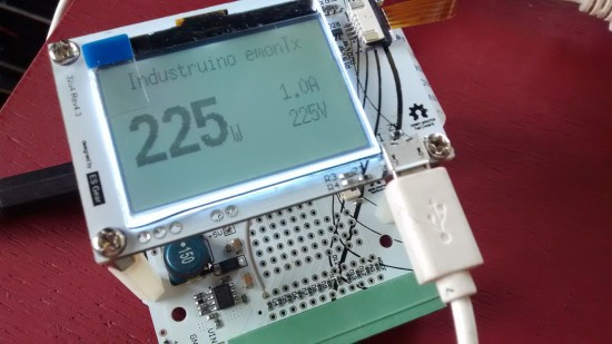
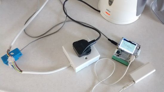
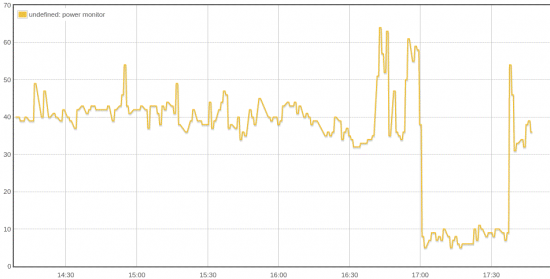
The team recently created an excellent tutorial showing how you to build an Arduino-based electricity consumption monitor with the Industruino PROTO platform. You can use it to measure AC power of your appliances, including a water cooker, TV, laptop charger, or anything else plugged into a wall socket. Alternatively, you can even use it in your electricity cabinet to evaluate the power consumption throughout your entire house (at least one phase).
The challenge is to measure an AC of a relatively high voltage (220-240V) with a direct current 5V Arduino MCU.
This may seem dangerous, but we will use a non-invasive Current Transformer (CT), so our Arduino remains galvanically isolated from the high voltage AC.
This prototype is based on the excellent open source project OpenEnergyMonitor. It uses parts of the its standard emonTx hardware and software to report the AC apparent power consumption, based on measurements of a Current Transformer as in the picture on the left. The original project also allows to measure 3 phase and/or real power, but for our prototype here we are only measuring the current of one phase, not its voltage which would require an AC/AC adaptor.
“The great thing about standards is that there are so many to choose from.” Truer words were never spoken, and this goes double for the hobbyist world of hardware hacking. It seems that every module, every company, and every individual hacker has a favorite way of putting the same pins in a row.
We have an entire drawer full of adapters that just go from one pinout to another, or one programmer to many different target boards. We’ll be the first to admit that it’s often our own darn fault — we decided to swap the reset and ground lines because it was convenient for one design, and now we have two adapters. But imagine a world where there was only a handful of distinct pinouts — that drawer would be only half full and many projects would simply snap together. “You may say I’m a dreamer…”
This article is about connectors and standards. We’ll try not to whine and complain, although we will editorialize. We’re going to work through some of the design tradeoffs and requirements, and maybe you’ll even find that there’s already a standard pinout that’s “close enough” for your next project. And if you’ve got a frequently used pinout or use case that we’ve missed, we encourage you to share the connector pinouts in the comments, along with its pros and cons. Let’s see if we can’t make sense of this mess.
FTDI TTL Serial
The de-facto standard for a hacker’s TTL serial pinout is definitely the layout that FTDI uses for their USB/TTL serial cables. Said cable is just so handy to have on hand that you’d be silly to use any other pinout for the job. And the good news is that the rest of the world has basically joined in. From the Chinese “Pro Mini” cloneduinos to the Hackaday Edition Huzzah ESP8266 board, and from Adafruit’s FTDI Friend to Modern Device’s USB-BUB, almost everyone uses this pinout. A victory for the common man!
There is one slight point of contention, however, and that’s whether pin 6 is DTR or RTS#. We never use either, so we couldn’t care less, but if you’re counting on your programmer sending the DTR signal to enter programming mode on the device (we’re looking at you Arduino!) then you’ll want DTR on pin 6, and the original FTDI cable, ironically, has the “wrong” pinout. Perhaps that’s why Sparkfun avoided the whole debacle and went their own way, breaking out every signal off the FTDI chip into their own unique configuration.
If you’re only going to break out TTL serial lines, you’d be a fool to use any other pinout.
Modules and Other Communications
Unlike the case with simple serial, connecting various kinds of modules to mainboards is a difficult problem. Creating a single pinout or connector specification for many potential protocols or arbitrary signals is a Herculean task. Surprisingly, it’s been done a few times over. Here are some notables.
Pmod
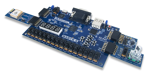
Digilent makes a wide range of FPGA demo boards, and they needed an in-house standard pinout that they could use to plug into various add-on peripheral modules that they sell. Thus Pmod was born. It has since become a full-fledged, and trademarked, open standard that you can use in your designs. Here’s the PDF version of the specification for you to print out, so you know they mean business.
There are a few aspects of Pmod that we think are particularly clever. First, the number of pins involved is “just right” at six, and it’s easily expandable. They use standard 0.1″ pitch pins and headers. Two lines carry power and ground, leaving four free pins for SPI, UART, or whatever else. The specification is that all power and signal voltages are 3.3 V because they’re designed for FPGAs after all. You can mix and match if you know what you’re doing, but they won’t let you call it Pmod(tm).
Eric Brombaugh’s iceRadio FPGA SDR, plugged together with Pmods
If you need more than four signals, there’s a twelve-pin version which is just two six-pin Pmods stacked into a double-row header. The extra power and ground are redundant, but it makes a twelve-pin output very flexible, because nothing stops it from being used as two sixes. The standard also says that the twelve-pin headers are to be spaced at 0.9″ center-to-center, so you can even connect two of them together when you need sixteen board-to-board signal connections. We like the modularity and expandability.
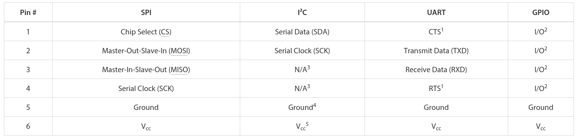
Pmod connectors are multi-protocol, but for each protocol there is a single pinout. So there’s an SPI Pmod and an I2C Pmod, and the pins are always in the same place. There isn’t a Pmod standard for every conceivable application, of course, so there’s a GPIO pinout that gives you free rein over what goes where. We think that it would be nice if some additional notable protocols (I2S? one-wire? servos? analog stereo audio?) were included in the specs, but the community can also handle these lower-level details.
In our eyes, Pmod is nearly perfect. It uses cheap hardware, is easily expandable, and the smallest incarnations are small enough to fit on all four sides of a one-inch-square board. If you’re willing to pay the brand-name premium, Digilent makes an incredible range of modules. We want to see more hackers outside of the FPGA scene get on it.
mikroBUS
What Digilent is to development boards in the US, MikroElektronika is in Europe. While Pmod aims to be capable of doing anything, Mikro-E’s mikroBUS connector wants to do everything, which is to say it has I2C, SPI, UART, two voltages, and even a few extra signals all on the same pinout. Physically, it’s two single rows of eight pins, spaced 0.9″ apart side-to-side, which means it fits into a breadboard nicely. Here’s the spec in PDF.
The tradeoff here, relative to Pmod, is that a lot of pins go unused on any given design. With (only) one “analog” channel, you wouldn’t choose mikroBUS to send stereo audio, whereas nothing stops you from calling the Pmod’s GPIO lines analog and sending four channels of sound. But that mikroBUS gains is fool-proofness. (Well, they could have also made it asymmetric…) There’s no chance of a newbie plugging an SPI module in where an I2C module is expected and scratching their heads. With mikroBus, it should just work.
Microchip has added a mikroBus port to their Curiosity boards, and MikroElektronika makes a ton of modules. If your audience consists of beginners, and one footprint for all protocols, it’s worth considering.
Seeed’s Grove
Meanwhile in China, Seeed Studios makes open-source modules, and makes them cheap. Their Grove connector uses only four pins, with power and ground among them. The have standard pinouts for UART, I2C, and for servo motors. Sensors and other analog peripherals are allocated one “primary” pin and one “secondary” and it’s assumed that you know what you’re doing. The idea behind their system is that you add a shield to your microcontroller board, and they break out the relevant pins into these four-pin Grove headers.
This is great for small things and I2C devices, which is Seeed’s catalog, but there just aren’t enough signal pins to run SPI or an analog RGB LED, for instance. But because of the small number of pins, they use very inexpensive polarized cables and shrouds that you can’t plug in the wrong way, and that take up relatively little board space. That’s Grove’s design trade-off.
Servo Motor control
One of these things is not like the others…
Hobby servo motors need three wires: voltage, ground, and a signal to tell them where to point. There are three distinct ways to arrange these wires, but Futaba, HiTec, Tower, GWS, and JR servos all chose to put them in SVG (or GVS) order, and there’s no reason to buck the trend. (Airtronics, what were you thinking?!)
SVG is also a handy pinout to use for all sorts of one-signal sensors or actuators where space is a premium, and we’ve seen this in a few designs (here and here, for instance). But we’re torn. Relative to the Grove, for instance, you’re just saving one pin. Even the Pmod would work with only three pins’ overhead. Is that worth complicating your life with another pinout? If you need a lot of powered one-signal devices, or servos, it probably is, and you can hardly beat SVG or GVS, whichever way you look at it.
Arduino
Viewed in the light of any of the other module interconnection systems, the Arduino is the worst of all worlds. It’s monolithic like mikroBUS, but it’s gigantic — you have to build a 55×73 mm board and accommodate 30 pins and pass-throughs if you’d like it to be stackable. The pins have a funny spacing (that gap!), that doesn’t fit any normal protoboard. Nobody goes through the trouble of building a shield just for an I2C connection. No wonder most Arduino projects look like a breadboard hedgehog. About the only good thing we can say about it is that it’s hard to plug one in backwards.
There’s also the tiny little factor that there’s a million Arduino shields out there, a huge community built around them, and widespread support for them. Which turns out to trump all of the reasonable design concerns. (Shakes head.)
Miscellany
Of course, there are other very specific pinouts that one might encounter, like the old ESP-01 module, or the XBee, or the nRF24. Adapting modules to fit boards is always going to be a pain, because the manufacturers will pick whatever suits them on that day. Programmer pinouts for specific microcontrollers are a similar story, as is JTAG, which is a beautiful standard with a dogs’ breakfast of pinout possibilities. (We could do a whole column!)
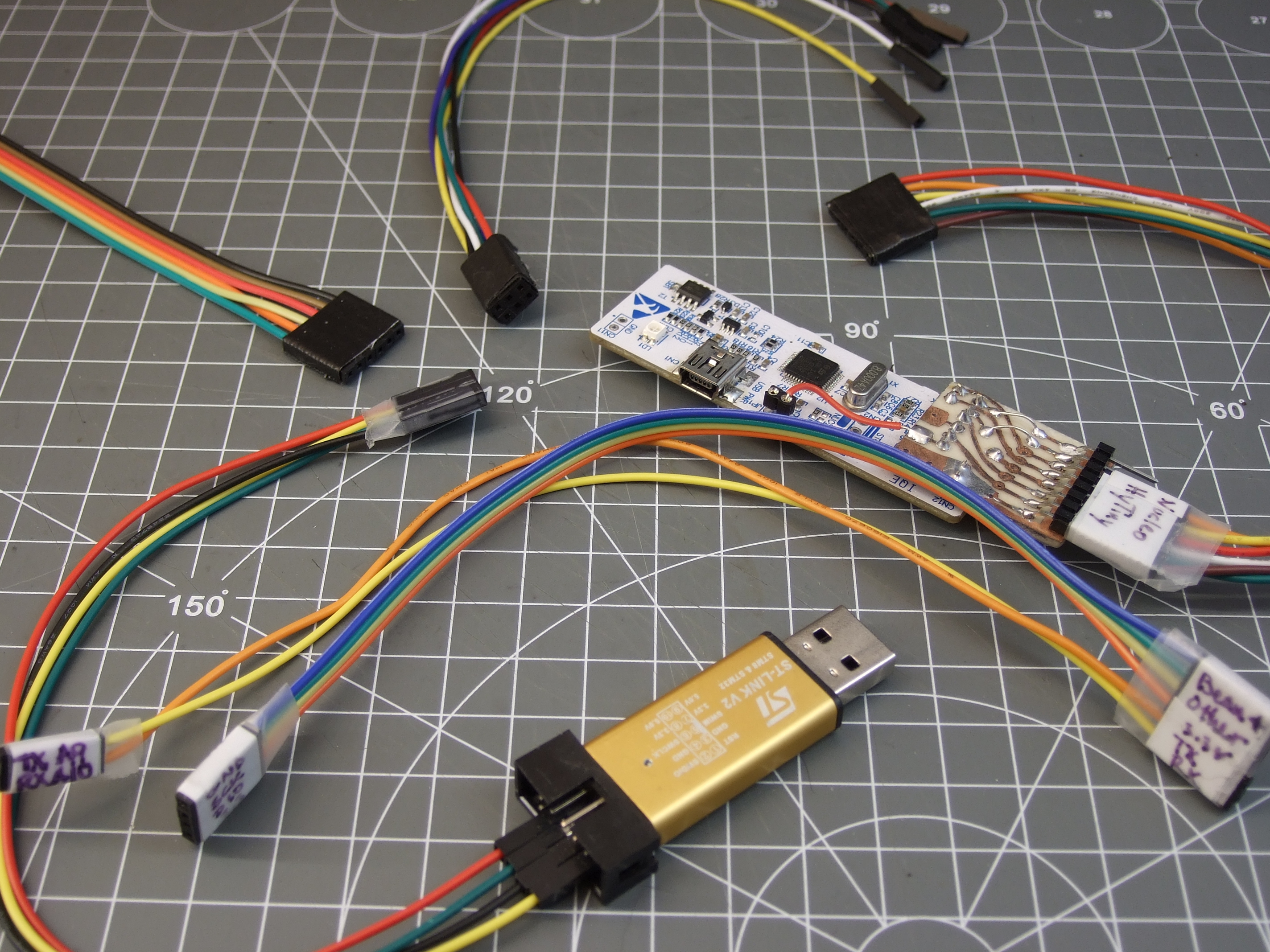
Faced with this inevitability, and the need for many one-off adapters, what can you do? What we do is buy a lot of those cheap “Dupont” female-to-female cables, get the connections working and tested, and then tape them permanently together and label them. It’s not as pretty as a dedicated PCB adapter, but it’s quick and easy and gets you moving on to what you wanted to do in the first place.
Wrapup and Recommendations
The goal of connectors, and their standards, is putting parts together. If you’re designing a sensor module with more than a couple components, and you want it to be maximally easy for yourself and others to hook up to whatever mainboard they’ve got, this is no easy task. The end result is a proliferation of translators, adapter boards, hats, shields, capes, or whatever else. We have a drawer and a half full, and we bet you do too.
Yes, I do see what I’m suggesting here. [source: xkcd 927]We’d be happy to see the world settle on Pmod for most needs, honestly, and we’d even throw away our beloved FTDI serial pinout in the name of standardization (or make an adapter). We can also see the need for exceptions like SVG / servo connectors when small sensors or multiples are in play. There will always be the need for dedicated on-board connectors as well, of course. Nobody said hardware was easy.
What’s your solution to the ultimate connector conundrum? Are there important connector systems that we’ve left out? What are their design tradeoffs? How stoked would you be if things could just plug together? Let us know!
As we’ve mentioned previously, the integrity of your vehicle in an era where even your car can have a data connection could be a dubious bet at best. Speaking to these concerns, a soon-to-be published paper out of the University of Birmingham in the UK, states that virtually every Volkswagen sold since 1995 can be hacked and unlocked by cloning the vehicle’s keyfob via an Arduino and software defined radio (SDR).
The research team, led by [Flavio Garcia], have described two main vulnerabilities: the first requires combining a cyrptographic key from the vehicle with the signal from the owner’s fob to grant access, while the second takes advantage of the virtually ancient HiTag2 security system that was implemented in the 1990s. The former affects up to 100 million vehicles across the Volkswagen line, while the latter will work on models from Citroen, Peugeot, Opel, Nissan, Alfa Romero, Fiat, Mitsubishi and Ford.
The process isn’t exactly as simple as putting together $40 of electronics and walking away with a vehicle. The would-be thief must be close in order to detect the fob’s unique key — although they only need to do so once for that vehicle! — as well as reverse-engineer the other half of the code from the vehicle’s internal network. Exploiting HiTag2’s vulnerabilities to unlock the vehicle can be achieved within a minute by a well-prepared thief. [Garcia] and his team note that only the VW Golf 7 has been spared from this exploit.
If thievery is not your thing and you’re looking to white-hat hack your vehicle, Volkswagen still has the best option in the form of the loveable Beetle.