Portable Bluetooth speakers have joined the club of ubiquitous personal electronics. What was once an expensive luxury is now widely accessible thanks to a prolific landscape of manufacturers mass producing speakers to fit every taste and budget. Some have even become branded promotional giveaway items. As a consequence, nowadays it’s not unusual to have a small collection of them, a fertile field for hacking.
But many surplus speakers are put on a shelf for “do something with it later” only to collect dust. Our main obstacle is a side effect of market diversity: with so many different speakers, a hack posted for one speaker wouldn’t apply to another. Some speakers are amenable to custom firmware, but only a small minority have attracted a software development community. It doesn’t help that most Bluetooth audio modules are opaque, their development toolchains difficult to obtain.
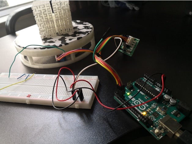
So what if we just take advantage of the best parts of these speakers: great audio fidelity, portability, and the polished look of a consumer good, to serves as the host for our own audio-based hacks. Let’s throw the Bluetooth overboard but embrace all those other things. Now hacking these boxes just requires a change of mindset and a little detective work. I’ll show you how to drop an Arduino into a cheap speaker as the blueprint for your own audio adventures.
Directing the Hacker Mindset at Myriad Bluetooth Speakers
There’s way too many different speakers out there for one hack to rule them all. But by changing our Bluetooth speaker mindset from “it’s a reprogrammable computer” to “it’s an integrated collection of useful electronic components”, we turn market diversity into our ally.
Look at this from the perspective of Bluetooth speaker manufacturers: they want their Bluetooth speaker to stand out from competitors, and the most obvious way is in their selection of loudspeaker drivers. Surprising the customer with big sound from a little box is key for success, so each product can offer a unique combination for driving the audio, all housed inside an eye-catching enclosure that lets consumers tell one portable Bluetooth speaker from another.
Tailoring for loudspeaker selection has cascading effects through the rest of the system. For best sound, they will need matching audio amplifier modules, which will have their own power requirements, which dictates battery performance, and so on. Catering to these desires, components are excluded from the tightly integrated mystery black boxes. Fortunately for hardware hackers, such an architecture also makes components easy to reuse:
- A rechargeable battery.
- Ability to charge that battery from USB.
- A low-power standby mode to monitor press of the power button.
- Protecting battery from over-discharge.
- A voltage regulator supplying battery power to the device.
- An audio line-in jack.
- Volume up/down control.
- Amplifier and driver.
All of these are useful for projects, already neatly packaged in a mass-produced enclosure.
Putting Theory Into Practice With An Example
Now that we have a general background, let’s apply this concept to a specific example. But before we begin, an obligatory note in case it is not obvious to any beginners reading this: This activity very definitely voids the warranty (do it, it’s worth it!), and modern portable electronics use lithium chemistry batteries that can be dangerous if mistreated.


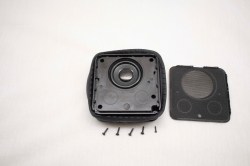

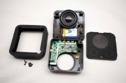

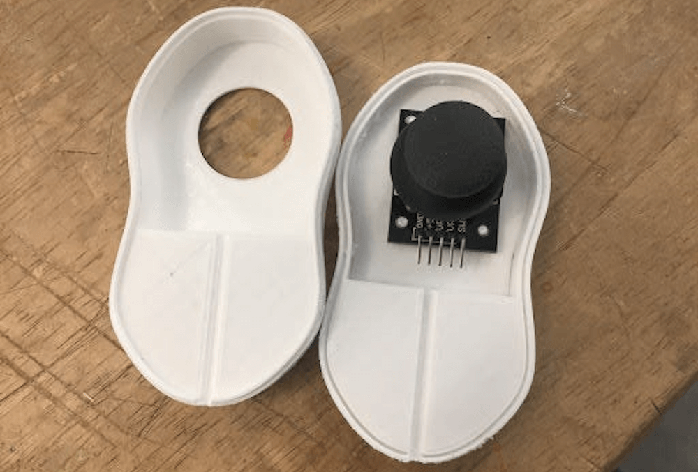
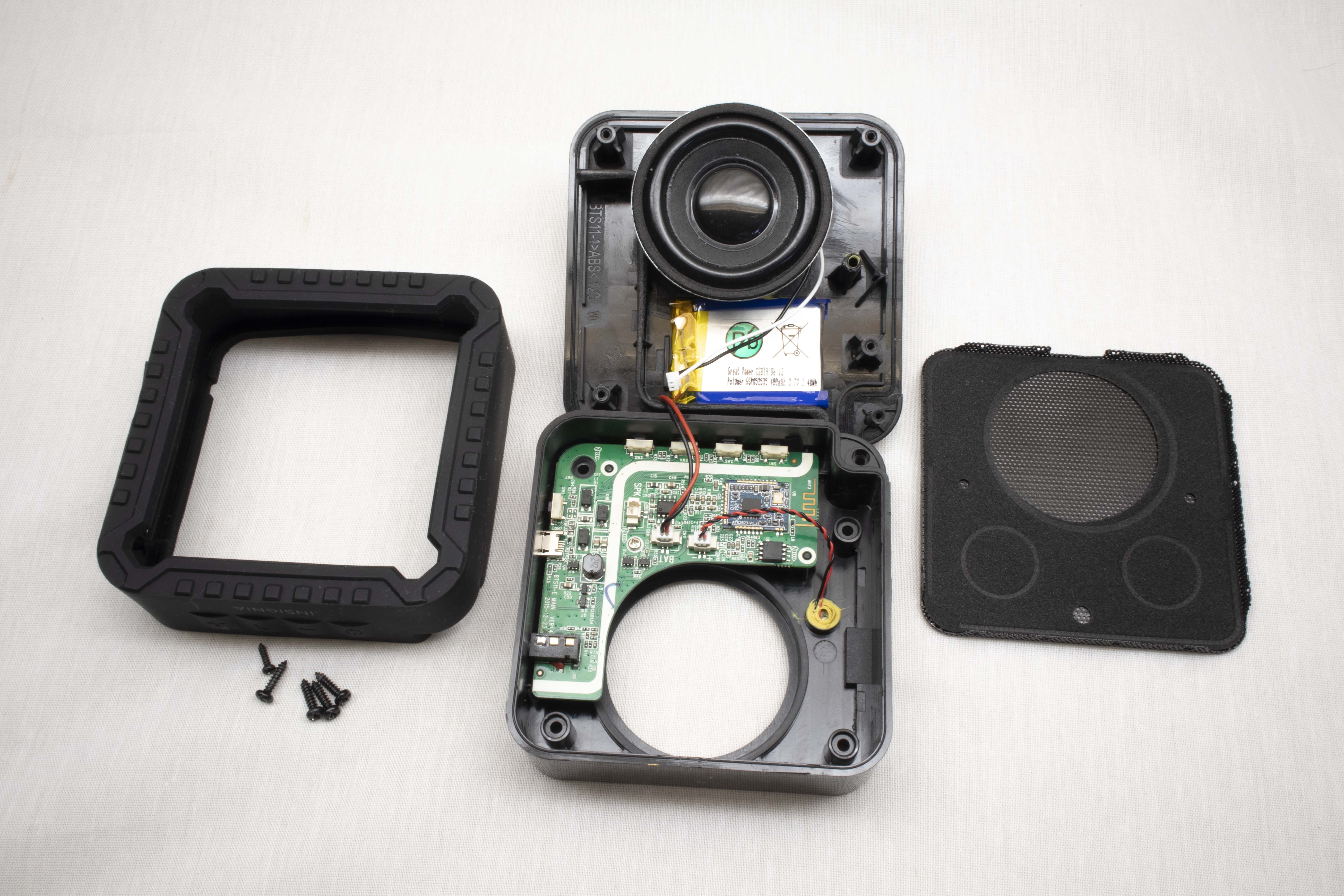
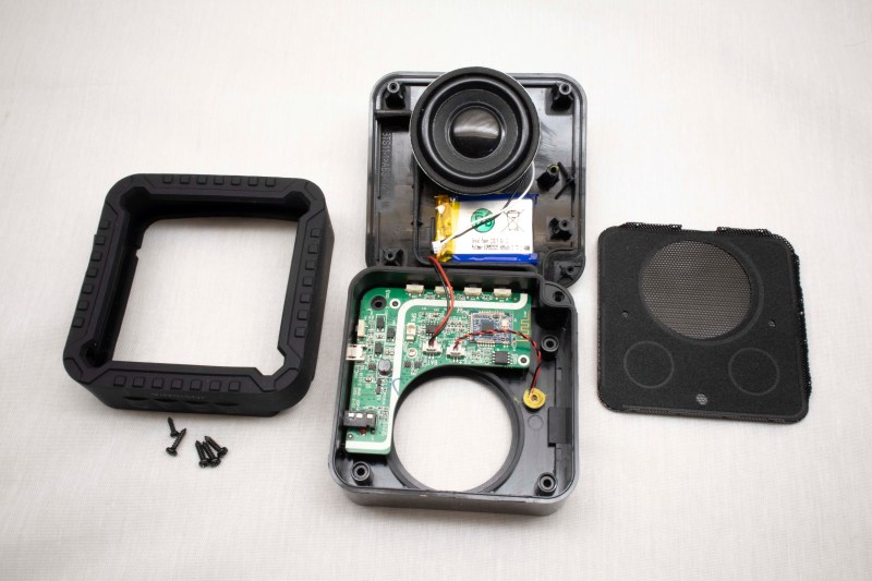
The Bluetooth speaker used in this example is a “Rugged Portable Bluetooth Speaker” sold by North American electronics retailer Best Buy under one of their house brands. A search of its FCC ID pointed to Lightcomm Technology Co. as the manufacturer. The “rugged” claim starts with a layer of soft rubber wrapped around its exterior. That plus reinforcements inside the case allows the speaker to absorb some level of abuse. I wanted to preserve this shock absorbing exterior and, thankfully, it was easy to open non-destructively. Even more care would be needed if it was a waterproof speaker (this one wasn’t) and moisture barriers need to be preserved. Alternatively, if the plan is to transfer the internals to another enclosure, the condition of the original box would not matter.
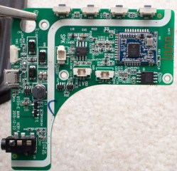
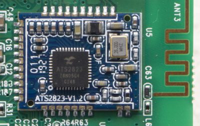 Once the circuit board has been extracted, the Bluetooth interface module should immediately stand out as the most sophisticated component sitting close to an antenna. A search for ATS2823 confirmed it is a module designed and sold for integration into Bluetooth audio products. Its MIPS M4K core and associated flash storage could be a promising start for firmware hacking, but the point of this example is to demonstrate how to hack a speaker utilizing existing firmware. So we will leave the module as-is.
Solder to the External Audio Input
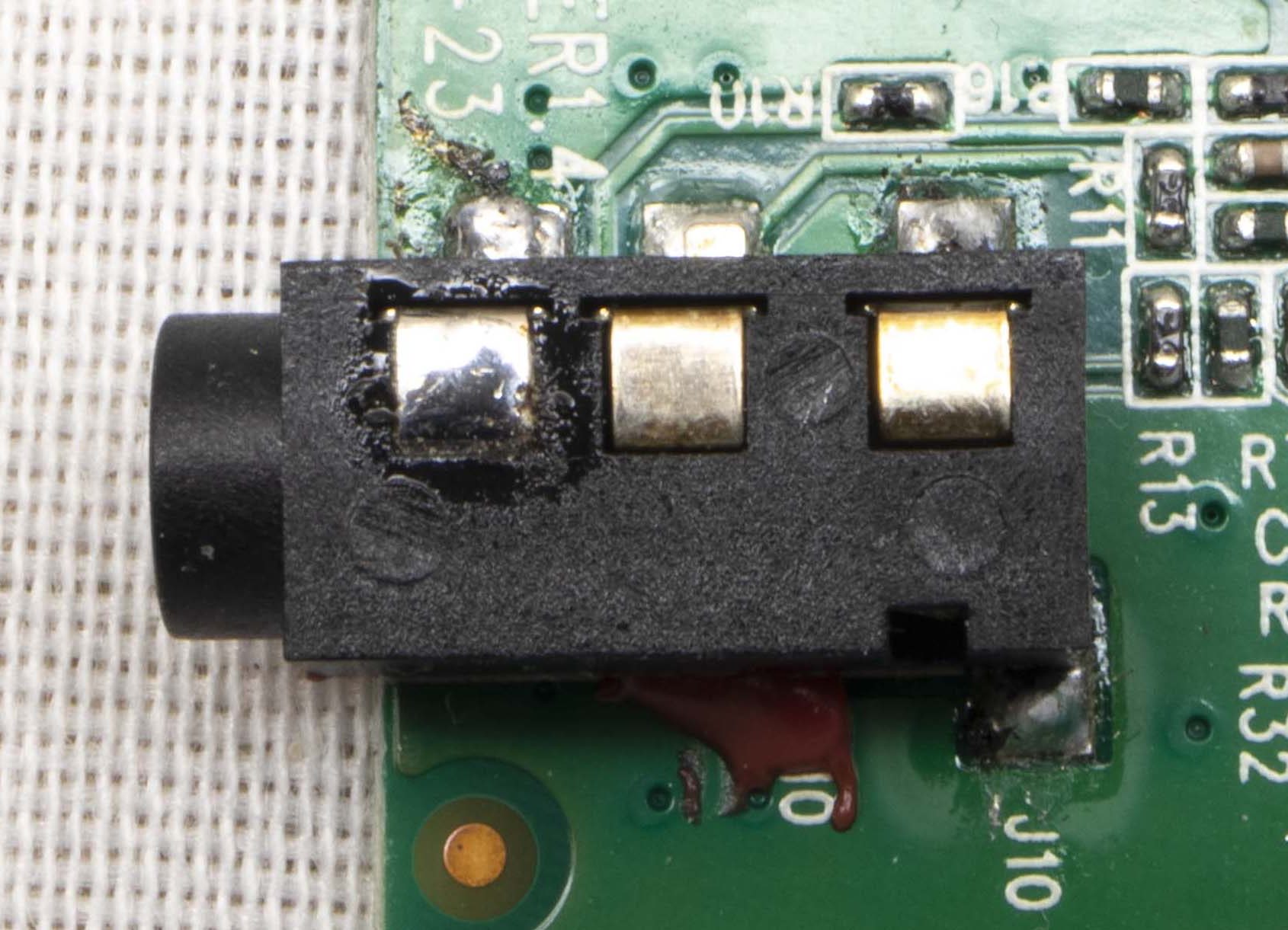
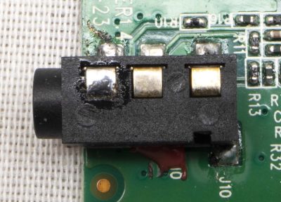 The easiest way to pipe audio into this system is to pretend to be an external audio source. We want the system to believe we are connected via an audio cable plugged into the line-in jack, but for compactness we’d prefer to do this without using an actual cord. This approach is easy, nondestructive, and preserves the existing volume control mechanism. There are a lot of different ways to implement an audio jack, so some exploration with a multimeter will be required. We need to find the standardized contacts for: audio input left channel, right channel, and ground. (Wikipedia reference: “Phone connector (audio)“)
It’ll be a little tricker to decipher the plug detection scheme, as it is not standardized. In this particular example, there is a fourth pin that floats in the absence of an audio plug. When an audio plug is present, the pin is grounded. Soldering a wire to always ground that detection pin will keep this speaker constantly in “playing external audio” mode.
Or Connect To Amplifier Directly
 An alternative approach is to bypass existing input and volume control, sending audio directly to the amplifier chip. To find this chip, we start with the voice coil wires and backtrack. It’ll likely be the largest component near those voice coil wires. Once the amplifier chip is found, consult the datasheet to find the input pins to cut free from the circuit and rewire for audio input that bypasses existing control.
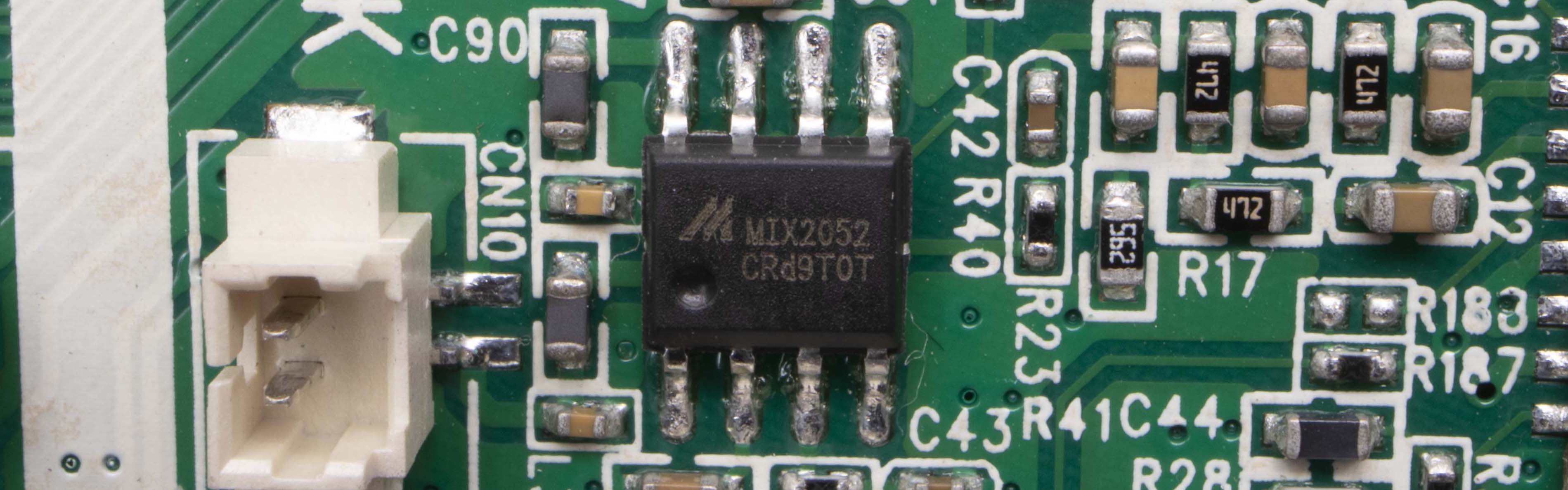
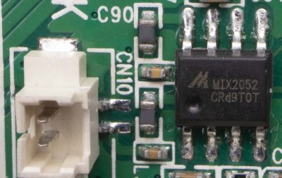
But even if we wish to maintain existing volume control, it is still useful to locate the audio amplifier chip. It is the most power-hungry component on the circuit board, and peak power requirements for the system are dictated by the amount of power this amplifier will draw when playing loudly. Therefore it is half the puzzle of calculating our available power. This particular Bluetooth device uses a Mixinno MIX2052 chip sitting adjacent to the voice coil wire connector, with a peak power of 6 watts.
Tap Into Power Supply
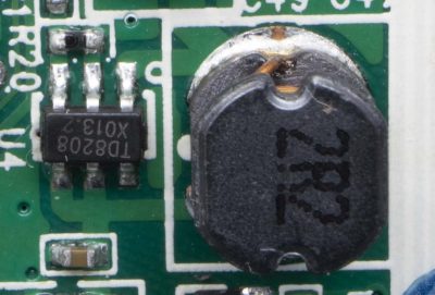
The other half of the puzzle is the voltage regulator delivering power to the amplifier chip. Similar to how we look for our amplifier near our voice coil wires, we can look for our regulator sitting near inductors, capacitors, and diodes. Once the power module is found, read its data sheet to determine peak power output.
The power budget for our hack would be constrained by power figures for those two components. Most microcontrollers consume maximum power during bootup. So as long as the audio source stays quiet during this time, we would have a little extra power to support boot. Somewhere between the regulator and the amplifier is also the best place to tap power. It allows us to piggyback on the existing power management circuit that shuts down the amplifier when entering low power mode, cutting power to our hack at the same time.
In the case of this board, there was one prominent coil and a Techcode TD8208 step-up regulator was found next to it. Configured to deliver 5 volts, this regulator can deliver 1A and tolerate brief spikes not to exceed 2A. This wouldn’t be enough to feed a Raspberry Pi 4, but plenty for an Arduino Nano.
Repurpose Control Button
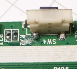 So far functionality for three of the four buttons on this speaker has been preserved: power, volume up, and volume down. The fourth button initiates Bluetooth pairing, or to pick up a phone call. We’re cutting BT out of the equation so this is no longer useful and can be repurposed.
On this speaker, SW4 is normally open and pulls to ground when pressed, making it trivial to reuse. I cut the trace leading to the Bluetooth interface module and soldered a wire so the switch now pulls an Arduino pin to ground when pressed.
Tuck Everything Back In

A few pieces of internal plastic reinforcements for ruggedness were cut away to create enough volume for an Arduino Nano inside this enclosure. It is no longer quite as rugged, but now it is far more interesting as a platform for sound hacks. To conclude this proof of concept, the Arduino Nano is using the Mozzi audio library to play the classic Wilhelm scream whenever our repurposed button is pressed.
Build Your Own Bleepy Bloopy Buzzy Box
Bluetooth used to be the novelty. With plenty of hacks
adding Bluetooth to existing audio equipment,
playing Bluetooth audio out of one, or
building our own Bluetooth speakers from scratch. But now Bluetooth speakers are ubiquitous, we’re approaching the point where Bluetooth is not necessarily the center of attention. Skipping the Bluetooth in a portable Bluetooth speaker gives us a new platform for our noise maker hacks. Something small, fun, and easy to bring to our next hacker show-and-tell meetup!