We’ve partnered with Thales, Telstra and Microsoft to pave the way for scalable security for connected IoT devices, by implementing a solution that enables trusted and secure end-to-end communication between device and cloud.
The solution enables instant and standardized mutual authentication between a device and a cloud platform via cellular networks, while fully-complying with GSMA IoT SAFE security specifications.
Within the IoT ecosystem, billions of devices collect, process and send data to the cloud, where a range of different IoT services are executed. To enable security, the IoT cloud service must have absolute trust in data received from connected devices. Equally, devices need to trust the cloud. This is only possible if the device and server are mutually authenticated. However, the IoT devices market is so fragmented — with a patchwork of different operating systems and chips being utilized — that security services scalability and duplication are very limited.
That’s why Thales, Telstra, Microsoft[1]and Arduino[2] have decided to team up to work on a solution that addresses the challenge of securely and efficiently connecting IoT devices to clouds in the most simplified way and through cellular networks. The level of trust required is enabled by a sophisticated ‘security-by-design’ approach for any IoT devices based on field-proven and standardized SIM or eSIM technology.
As a result, as soon as an IoT device is switched on, any SIM or eSIM featuring Thales’s IoT SAFE application is automatically and securely provisioned. Once the IoT device gets a proper Digital Certificate created and stored in the SIM/eSIM, then a trusted communication between the device and the server is permitted, in full respect of data integrity and confidentiality.
“We are very pleased to be part of the dream team composed by Thales, Telstra and Microsoft,” said Fabio Violante, Arduino CEO. “The development of this tool was a teamwork and a proof that Arduino is a great partner to create solid, reliable and easy to integrate hardware and software IoT solutions.“
[1] Microsoft integrated the IoT SAFE solution with their Azure IoT Hub and also provided Azure Stream Analytics, Cosmos DB and Power BI services to quickly enable the development of an example end-to-end IoT application.
[2] We developed a library (under an open source license) that implements the security mechanism of the GSMA IoT Safe standard on our MKR NB 1500 boards and provides a valid alternative to the usage of the crypto chip already present on the Arduino board. The project has been a great example of collaborations with companies operating in various IoT sectors through our brand new Arduino Pro division.
It’s been a long time since we first launched our Arduino IDE inspired by the glorious Processing interface, and what started as a Java UI wrapper for build scripts has gone through countless iterations over the past fifteen years.
Some may remember the transition between 1.0 and 1.5, or the application’s icon being replaced, but behind the scenes where many of our users don’t go look, we’ve completely overhauled the way libraries are included, code is cleaned, fail-safe measures are implemented, and a sketch is built.
At the same time our more advanced users have been implementing workarounds to use our internal builder command in their workflows for the most diverse reasons.
Projects have spawned to create Arduino-based makefiles, build scripts, code linters ,and snippets to program their boards using their favorite code editors, and we’ve seen people use Eclipse, Sublime Text, VS Code, Vi(m), Emacs, or even XCode to create Arduino projects.
We keep our eyes peeled when it comes to how our community uses our tools and try as much as possible to learn from it, and this inspired us to get back to the drawing board.
The software that makes up the Arduino platform has grown incrementally over time — new features were added and sometimes the need to quickly factor in those changes did not make it easy to foresee how things would develop years ahead. This led to a situation in which multiple chunks of code and functionalities were spread across different Arduino software products (the Java IDE, the Create Agent, the Web Editor servers, upload/discovery tools, etc.), some of them overlapping or redundant.
The needs of our community, as well as our own, prompted us to radically rethink our approach and embark on a major refactoring operation with the goal to obtain a single reference implementation: the Arduino Command Line Interface.
As we move forward, all our legacy products are being reworked to use the Arduino CLI as the foundation to build upon.
We believe this effort will provide our users and ourselves with more advanced, flexible tools that we can all benefit from.
From that moment on we concentrated our efforts into adding features, smoothing out some edges, and improving the CLI usability, largely based on users’ feedback from within our community (check out our latest release on GitHub).
A tool to enable advanced workflows
Having a flexible yet simple command line tool providing all the features and flexibility that made Arduino a successful platform can enable users to find new ways of improving their productivity. A great example is how Arduino CLI has been used in Continuous Integration processes, a great example of which came from our friends at TensorFlow, a popular open source machine learning framework. This encouraged us to provide an official Arduino CLI GitHub Action.
This application demonstrates how the Arduino CLI is not just a command line tool, but contains all you need to easily build applications around the Arduino ecosystem. Parse the JSON output of the CLI or implement it as an always-on service that accepts commands via a gRPC interface using your language of choice.
We use gRPC in our Pro IDE and in recent releases of our classic Java IDE.
If you like, you can even use it in your Go application as a library. Our Web Editor services are built using this approach.
How it works
Arduino CLI allows you to replicate the same workflows you are used to with our IDE by using simple commands in a shell, your CI workflow, or wherever you see fit:
Install the board package and your favorite libraries on your PC.
Create a sketch using your favorite editor.
Compile and upload the sketch to your board.
We’re soon going to release our CLI primer to get you all onboard. Check out the trailer below for a sneak peek!
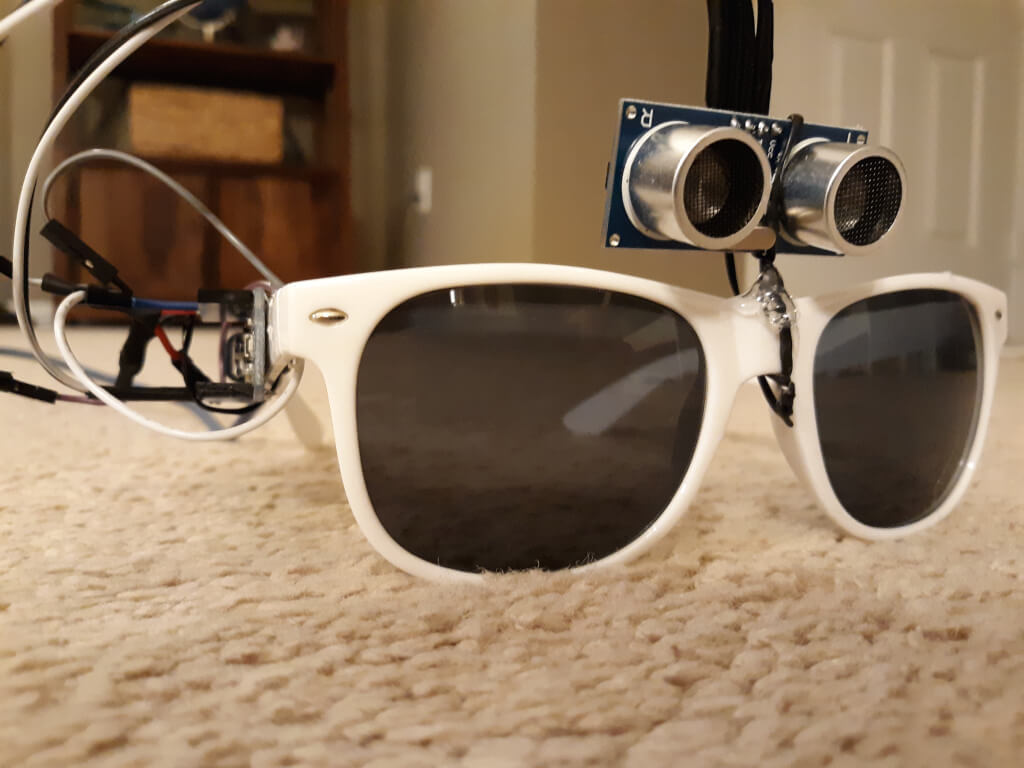
Touching your face is a subconscious behavior that we all do, and it is also an easy way to pick up illnesses like the coronavirus and flu. However, like many infectious diseases, proper hygiene can help reduce your risk. With this in mind, Nick Bild designed a simple solution in the form of a modified pair of glasses to provide a subtle reminder not to go near your eyes, mouth, and nose.
The project, which Bild calls Sentinel, consists of an ultrasonic sensor mounted on top of the bridge and an Arduino Nano along the temple. Whenever a hand (or object) is detected in close proximity to the face, a red warning LED lights up in the wearer’s peripheral vision.
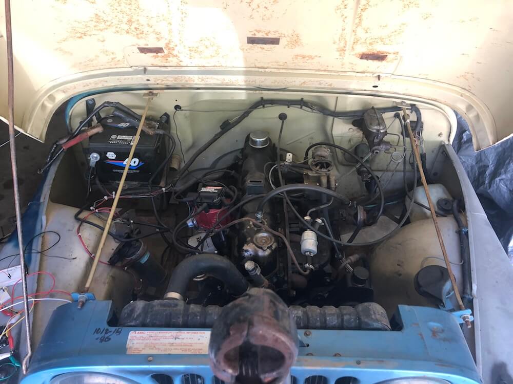
The build uses the laptop’s Enhanced Dictation functionality to convert text into speech, and when a Python program receives the proper keywords, it sends an “H” character over serial to an Arduino Uno to activate the vehicle.
The Uno uses a transistor to control a 12V relay, which passes current to the Jeep’s starter solenoid. After a short delay, the MacBook then transmits an “L” command to have it release the relay, ready to do the job again when needed!
As a fan of Iron Man, Forsyth channeled his inner Tony Stark and even programmed the system to respond to “JARVIS, let’s get things going!”
This is a guest post from Surrogate, a team of developers building games that people play in real-life over the internet.
We introduced this concept last year, and have launched 3 games so far. Our final game of 2019 was SumoBots Battle Royale — where players from anywhere in the world can fight real robots on a battle royale style arena. The aim of the project was to have the game run semi-autonomously, meaning that the bots could self-reset in between the games, and the arena could run by itself with no human interaction. This was our most complex project to date, and we wanted to share some parts of the build process in more detail, specifically, how we’ve built these robots and hooked them online for people to control remotely.
Robot selection
We’ve started our process by choosing which robots we’d want to use for the game. There were a couple of requirements for the robots when making the evaluation:
Are able to withstand 24/7 collision
Easily modifiable and fixable
Can rotate on the same spot
Must have enough space to fit the electronics
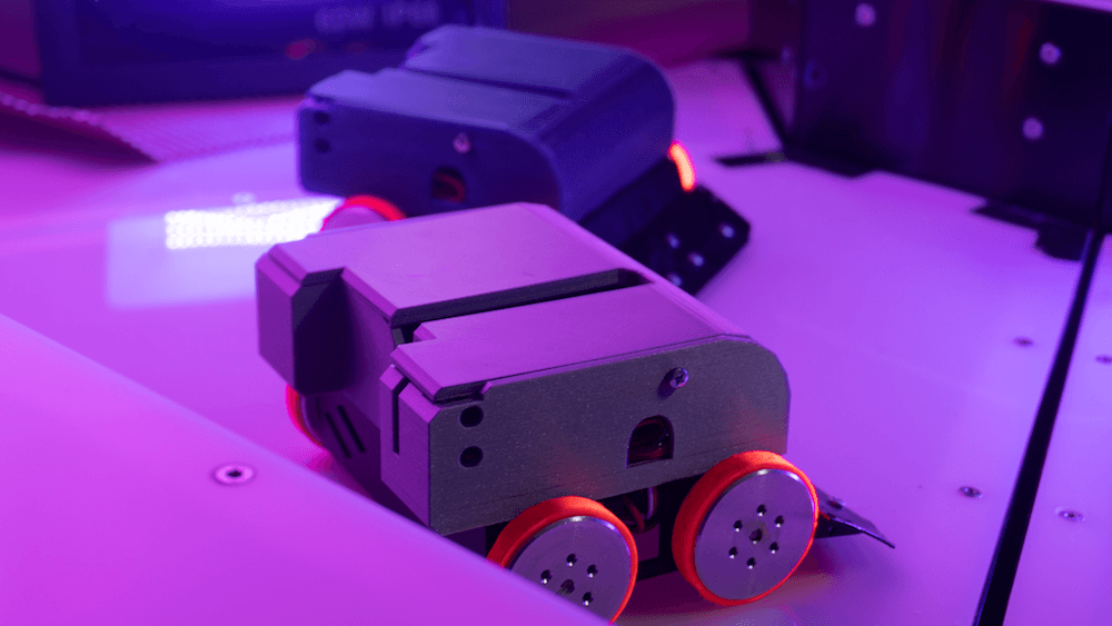
After looking at a lot of different consumer robots, maker projects, and competitive fighting bots, we’ve decided to use the JSUMO BB1 robots for this game. We liked the fact that these bots have a metal casing which makes them very durable, all parts are easily replaceable and can be bought separately, and it has 4 independent motors (motor shields included), one for each wheel, which allows it to rotate on the same spot.
We were pretty skeptical of being able to fit all the electronics into the original casing, but we decided to go with this robot anyways, as it had the best overall characteristics. As this robot is easily modifiable, we can always 3D print an extra casing to fit all the parts.
What is the board?
Now that we’ve decided on the robot, it was the time to define what electronics should we use in this build. As usual, it all starts with the requirements. Here’s what we need for the game to run smoothly:
The robot should be able to recover from any position
Can stay online while charging
Supports WiFi network connection and offers reliable connectivity
Easily programmable and supports OTA updates
Can control 4 motors simultaneously
Based on these requirements we had the following electronics layout in mind:
We had to find a board that is energy efficient, can send commands to motors, supports parallel charging and has a small footprint on the robot size. With so many requirements, finding the perfect board can be a challenge.
Arduino to the rescue
Fortunately, Arduino was there to help us out. They offer a rich selection of boards to fit every possible robotics project out there and have very detailed documentation for each of the boards.
More importantly, Arduino is known for its high quality, something that is crucial for semi-autonomous types of applications. Coming from an embedded software background and having to work with all sorts of hardware, we often see that some features or board functionalities are not fully finished which can lead to all sorts of unpleasant situations.
After looking at the Arduino’s collection of boards we quickly found a perfect candidate for our project, the Arduino MKR1000 WiFi. This board fits all of our main requirements for the motor controls, is easily programmable via Arduino IDE, and due to its low power design is extremely power efficient, allowing us to have a lower capacity battery. Additionally, it has a separate WiFi chip onboard, which solely focuses on providing a reliable WiFi connection, something that is very important in our use case.
Now that we’ve decided on the “brain” of our robot, it was time to choose the rest of the components.
Robust hardware means working software
Something to keep in mind is that when working with hardware, you should always try to avoid any possible risks. This means that you should always over-do your minimal hardware requirements where possible. The reason is — if your hardware doesn’t work as intended, your whole software stack becomes unusable too. Always chose reliable hardware components for mission-critical applications.
Some of our electric components might look a bit overkill, but due to the nature of our projects, they are a critical requirement.
Avoiding the battery explosions
As there is a lot of robot collision involved in the game, we decided to go with a high safety standard battery solution. After evaluating multiple options on the market, we decided to go with the RRC2040 from RRC (Germany). It has a capacity of 2950 MaH that allows us to run the robots for up to 5 hours on a single charge. It has an internal circuitry for power management, protection features and it supports SMBUS communications (almost like I2C), and is certified for all of the consumer electronics battery standards. For charging, we used RRC’s charging solution designed specifically for this battery and that offers the possibility to feed power to the application while the battery is being charged.
Note: the Arduino MKR1000 has a pretty neat charging solution on the board itself. You can connect the battery to the board directly as the main power source, and you charge it directly through the MKR1000’s micro USB port. We really wanted to use it to save space and have a more robust design, but due to the large capacity of our battery, we couldn’t use it at full potential. In our future projects with smaller scale robots, we definitely plan to use the board’s internal charging system, as it works perfectly for 700-1800 MaH power packs.
Bot recovery
For the bot to be able to recover from falling on its head, we’ve implemented a flipping servo. We didn’t want to have any risk of not enough torque, so we went with DS3218, which is capable of lifting up to 20KG of weight. Here’s how it works:
Hooking everything together
Now that we’ve decided on all of the crucial elements of this setup, it was time to connect all the elements together. As the first step, we figured what would be the best step way to locate all the pieces within the bot. We then 3D-printed a casing to protect the electronics. With all of the preliminary steps completed, we’ve wired all of the components together and mounted them inside of the casing. Here’s how it looks:
It was really convenient for us that all the pins on the board could be connected just by plugging them in, this avoids a lot of time spent on soldering the cables for 12 robots and more importantly, allowed us to cut out the risk of bad soldering that usually can’t be easily identified.
Arduino = Quick code
Arduino MKR1000 offered us the connectivity we needed for the project. Each sumo robot hosts their own UDP server using MKR1000 WiFi libraries to receive their control commands for a central control PC and broadcasting their battery charge status. The user commands are translated to 3 different PWM signals using Arduino Servo library for the flipping, left and right side motor controllers. The board used has support for hardware PWM output which was useful for us. Overall we managed to keep the whole Arduino code in a few hundred lines of code due to the availability of Servo and Wifi libraries.
The out of the box ArduinoOTA support for updating the code over the WiFi came in handy during the development phase, but also anytime we update the firmware for multiple robots at the same time. No need to open the covers and attach a USB cable! We created a simple Bash script using the OTA update tool bundled in Arduino IDE to send firmware updates to every robot at the same time.
To summarize
It’s pretty amazing that we live in the age where you can use a mass market tiny, small form factor board like the Arduino MKR1000 and have so much functionality. We’ve had a great experience developing our SumoBots Battle Royale game using the MKR1000 board. It made the whole process very smooth and streamlined, the documentation was right on point, and we never had to hit a bottleneck where the hardware wouldn’t work as expected.
More importantly, the boards have proven to be very robust throughout the time. These SumoBots have been used for more than 3000 games already, and we haven’t seen a single failure from the Arduino MKR1000. For a game where you literally slam the robots in to each other at a high speed, that’s pretty impressive to say the least.
We look forward to working with Arduino on our future games, and we can’t wait to see what they will be announcing in 2020!
Music and synchronized lighting can be a beautiful combination, evident by panGenerator’s recent installation that was commissioned by the M?skie Granie concert tour in Poland.
The interactive sculpture was comprised of 15 drums that trigger waves of light traveling toward a huge helium-filled sphere floating above the area, appearing to charge it with sound and light energy as the instruments are played.
“The audience was invited to drum collectively and together create an audio-visual spectacle – intensity of which depended on the speed and intensity of the drumming. That fulfilled the main goal of creating interactive art experience in which the audience can actively participate in the event rather than just passively enjoy the music, gathering and playing together.”
The project incorporated 200 meters of addressable RGB LEDs and measured in at roughly 300 square meters, making it likely the biggest such build ever seen there. According to the designers, each of the drums featured a custom PCB equipped with an Arduino Nano and microphone, and used an MCP2515-based CAN setup for communication.
All of this was assembled and taken down seven times over two months in cities around the country. Be sure to check out this dazzling display in action in the video below!
This post is from Massimiliano Pippi, Senior Software Engineer at Arduino.
The Arduino IoT Cloud platform aims to make it very simple for anyone to develop and manage IoT applications and its REST API plays a key role in this search for simplicity. The IoT Cloud API at its core consists of a set of endpoints exposed by a backend service, but this alone is not enough to provide a full-fledge product to your users. What you need on top of your API service are:
Good documentation explaining how to use the service.
A number of plug-and-play API clients that can be used to abstract the API from different programming languages.
Both those features are difficult to maintain because they get outdated pretty easily as your API evolves but clients are particularly challenging: they’re written in different programming languages and for each of those you should provide idiomatic code that works and is distributed according to best practices defined by each language’s ecosystem.
Depending on how many languages you want to support, your engineering team might not have the resources needed to cover them all, and borrowing engineers from other teams just to release a specific client doesn’t scale much.
Being in this exact situation, the IoT Cloud team at Arduino had no other choice than streamlining the entire process and automate as much as we could. This article describes how we provide documentation and clients for the IoT Cloud API.
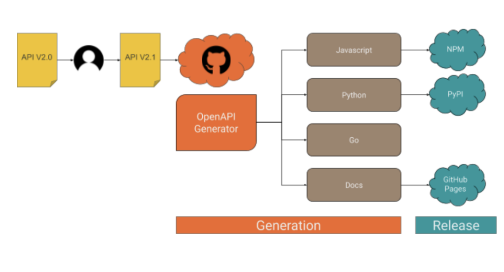
Clients generation workflow
When the API changes, a number of steps must be taken in order to ship an updated version of the clients, as it’s summarized in the following drawing.
As you can see, what happens after an engineer releases an updated version of the API essentially boils down to the following macro steps:
1. Fresh code is generated for each supported client. 2. A new version of the client is released to the public.
The generation process
Part 1: API definition
Every endpoint provided by the IoT Cloud API is listed within a Yaml file in OpenAPI v3 format, something like this (the full API spec is here):
/v2/things/{id}/sketch:
    delete:
      operationId: things_v2#deleteSketch
      parameters:
      - description: The id of the thing
        in: path
        name: id
        required: true
        schema:
          type: string
      responses:
        "200":
          content:
            application/json:
              schema:
                $ref: '#/components/schemas/ArduinoThing'
          description: OK
        "401":
          description: Unauthorized
        "404":
          description: Not Found
The format is designed to be human-readable, which is great because we start from a version automatically generated by our backend software that we manually fine-tune to get better results from the generation process. At this stage, you might need some help from the language experts in your team in order to perform some trial and error and determine how good the generated code is. Once you’ve found a configuration that works, operating the generator doesn’t require any specific skill, the reason why we were able to automate it.
Part 2: Code generation
To generate the API clients in different programming languages we support, along with API documentation we use a CLI tool called openapi-generator. The generator parses the OpenAPI definition file and produces a number of source code modules in a folder on the filesystem of your choice. If you have more than one client to generate, you will notice very soon how cumbersome the process can get: you might need to invoke openapi-generator multiple times, with different parameters, targeting different places in the filesystem, maybe different git repositories; when the generation step is done, you have to go through all the generated code, add it to version control, maybe tag, push to a remote… You get the gist.
To streamline the process described above we use another CLI tool, called Apigentools, which wraps the execution of openapi-generator according to a configuration you can keep under version control. Once Apigentools is configured, it takes zero knowledge of the toolchain to generate the clients – literally anybody can do it, including an automated pipeline on a CI system.
Part 3: Automation
Whenever the API changes, the OpenAPI definition file hosted in a GitHub repository is updated accordingly, usually by one of the backend engineers of the team. A Pull Request is opened, reviewed and finally merged on the master branch. When the team is ready to generate a new version of the clients, we push a special git tag in semver format and a GitHub workflow immediately starts running Apigentools, using a configuration stored in the same repository. If you look at the main configuration file, you might notice for each language we want to generate clients for, there’s a parameter called ‘github_repo_name’: this is a killer feature of Apigentools that let us push the automation process beyond the original plan. Apigentools can output the generated code to a local git repository, adding the changes in a new branch that’s automatically created and pushed to a remote on GitHub.
The release process
To ease the release process and to better organize the code, each API client has its own repo: you’ll find Python code in https://github.com/arduino/iot-client-py, Go code in https://github.com/arduino/iot-client-go and so on and so forth. Once Apigentools finishes its run, you end up with new branches containing the latest updates pushed to each one of the clients’ repositories on GitHub. As the branch is pushed, another GitHub workflow starts (see the one from the Python client as an example) and opens a Pull Request, asking to merge the changes on the master branch. The maintainers of each client receive a Slack notification and are asked to review those Pull Requests – from now on, the process is mostly manual.
It doesn’t make much sense automate further, mainly for two reasons:
Since each client has its own release mechanism: Python has to be packaged in a Wheel and pushed to PyPI, Javascript has to be pushed to NPM, for Golang a tag is enough, docs have to be made publicly accessible.
We want to be sure a human validates the code before it’s generally available through an official release.
Conclusions
We’ve been generating API clients for the IoT Cloud API like this for a few months, performing multiple releases for each supported programming language and we now have a good idea of the pros and cons of this approach.
On the bright side:
The process is straightforward, easy to read, easy to understand.
The system requires very little knowledge to be operated.
The time between a change in the OpenAPI spec and a client release is within minutes.
We had an engineer working two weeks to set up the system and the feeling is that we’re close to paying off that investment if we didn’t already.
On the not-so-bright side:
If operating the system is trivial, debugging the pipeline if something goes awry requires a high level of skill to deep dive into the tools described in this article.
If you stumble upon a weird bug on openapi-generator and the bug doesn’t get attention, contributing patches upstream might be extremely difficult because the codebase is complex.
Overall we’re happy with the results and we’ll keep building up features on top of the workflow described here. A big shoutout to the folks behind openapi-generator and Apigentools!
We’ve released the first prototype of one of the most requested Arduino Pro IDE features:the Arduino Debugger
Key features
executes your Arduino sketch step-by-step while it’s running on your Arduino board!
pause your sketch execution placing breakpoints
inspect variables values during execution
Initially supporting SAMD21 boards the Arduino Pro IDE debugger is available for Windows, Mac OSX and Linux64.
You can try the Arduino Debugger as a feature of the latest Alpha preview version for the Arduino Pro IDE; more details like tutorials etc will follow on soon!
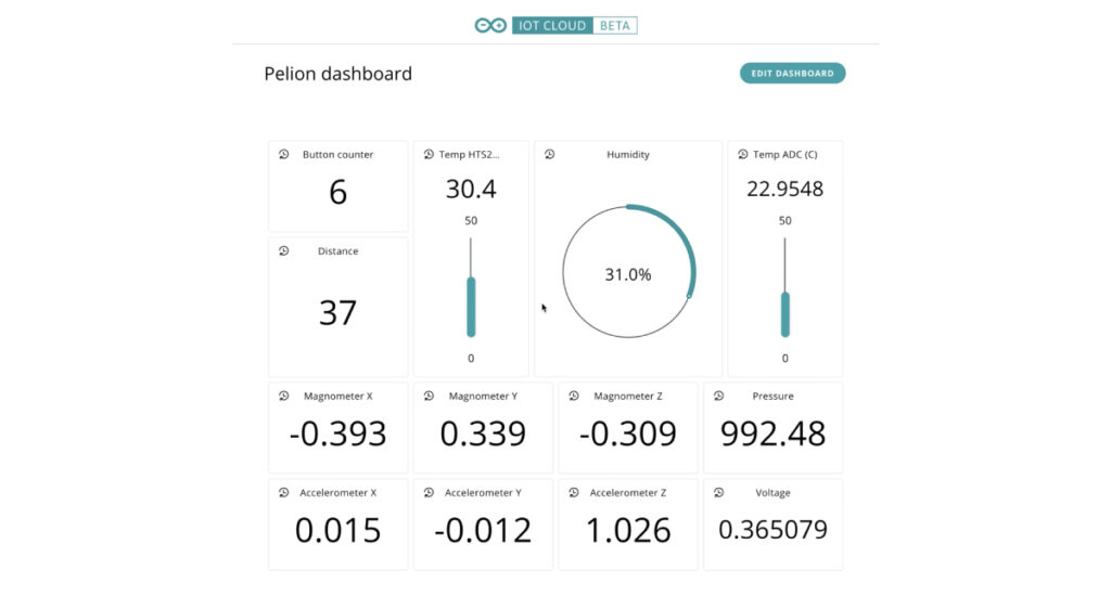
As part of Arduino’s expanding relationship with Arm and continuing commitment to professionals, Arm Pelion Device Management users can now seamlessly use Arduino IoT Cloud to quickly create IoT applications.
Combining the speed of application development of the low-code Arduino IoT Cloud with the secure, scalable lifecycle management features of Arm Pelion Device Management brings the best of both worlds.
The integration enables Pelion Device Management users to import all their resources via the Pelion API and translate them into Arduino IoT Cloud properties. They can see and manage everything in the cloud, with the Arduino IoT interface (web or mobile client) providing the simplicity for designers to focus their efforts on the IoT application, creating control panels and summary dashboards. Scalability is a fundamental of the Pelion Device Management service, and new devices will automatically appear in the Arduino IoT Cloud as soon as they are registered in Pelion.
If you are an existing client of Pelion Device Management and would like to know more about the integration with Arduino IoT Cloud and the professional services available from the Arduino Pro team, please contact us here.
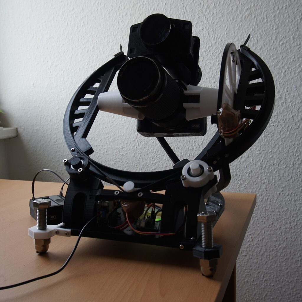
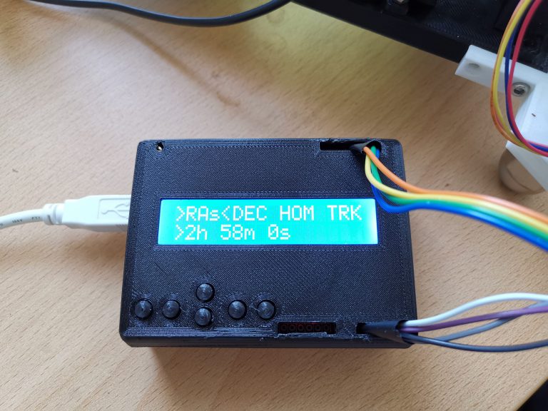
Stars appear to stand still, but wait a few minutes and they won’t be in quite the same place. This means that if you want to take a long-exposure image of the sky with your DSLR you’ll have to either embrace the streaks, or use tracking hardware to compensate for this movement. Naturally, this specialized equipment can be quite expensive, but a seen here, you can now make your own 3D-printed OpenAstroTracker controlled by an Arduino Uno.
The device features a 16×2 LED display/keypad shield, along with an optional Bluetooth module for interface. When set up, it slowly rotates the camera to compensate for star movements via two steppers on a gimbal assembly.