

2025: As The Hardware World Turns

If you’re reading this, that means you’ve successfully made it through 2025! Allow us to be the first to congratulate you — that’s another twelve months of skills learned, projects started, and hacks….hacked. The average Hackaday reader has a thirst for knowledge and an insatiable appetite for new challenges, so we know you’re already eager to take on everything 2026 has to offer.
But before we step too far into the unknown, we’ve found that it helps to take a moment and reflect on where we’ve been. You know how the saying goes: those that don’t learn from history are doomed to repeat it. That whole impending doom bit obviously has a negative connotation, but we like to think the axiom applies for both the lows and highs in life. Sure you should avoid making the same mistake twice, but why not have another go at the stuff that worked? In fact, why not try to make it even better this time?
As such, it’s become a Hackaday tradition to rewind the clock and take a look at some of the most noteworthy stories and trends of the previous year, as seen from our rather unique viewpoint in the maker and hacker world. With a little luck, reviewing the lessons of 2025 can help us prosper in 2026 and beyond.
Love it or Hate it, AI is Here
While artificial intelligence software — or at least, what passes for it by current standards — has been part of the technical zeitgeist for a few years, 2026 was definitely the year that AI seemed to be everywhere. So much so that the folks at Merriam-Webster decided to make “slop”, as in computer-generated garbage content, their Word of the Year. They also gave honorable mention to “touch grass”, which they describe as a phrase that’s “often aimed at people who spend so much time online that they become disconnected from reality.” But we’re going to ignore that one for personal reasons.
At Hackaday, we’ve obviously got some strong feelings on AI. For those who earn a living by beating the written word into submission seven days a week, the rise of AI is nothing less than an existential crisis. The only thing we have going for us is the fact that the average Hackaday reader is sharp enough to recognize the danger posed by a future in which all of our media is produced by a Python script running on somebody’s graphics card and will continue to support us, warts and all.

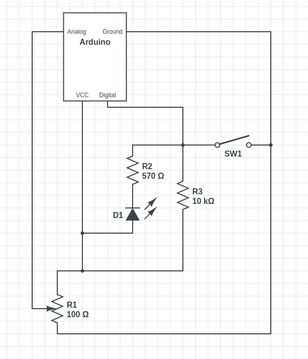
But while most of us are on the same page about AI in regards to things like written articles or pieces of art, it’s not so clear cut when it comes to more utilitarian endeavours. There’s a not insignificant part of our community that’s very interested in having AI help out with tedious tasks such as writing code, or designing PCBs; and while the technology is still in its infancy, there’s no question the state of the art is evolving rapidly.
For a practical example we can take a look at the personal projects of two of our own writers. Back in 2023. Dan Maloney had a hell of a time getting ChatGPT to help him design a latch in OpenSCAD. Fast forward to earlier this month, and Kristina Panos convinced it to put together a customized personal library management system with minimal supervision.
We’ve also seen a uptick in submitted projects that utilized AI in some way. Kelsi Davis used a large language model (LLM) to help get Macintosh System 7 running on x86 in just three days, Stable Diffusion provided the imagery for a unique pizza-themed timepiece, Parth Parikh used OpenAI’s Speech API to bring play-by-play commentary to PONG, and Nick Bild used Google Gemini to help turn physical tomes into DIY audio books.
Make no mistake, an over-reliance on AI tools can be dangerous. In the best case, the user is deprived of the opportunity to actually learn the material at hand. In the worst case, you make an LLM-enhanced blunder that costs you time and money. But when used properly, the takeaway seems to be that a competent maker or hacker can leverage these new AI tools to help bring more of their projects across the finish line — and that’s something we’ve got a hard time being against.
Meshtastic Goes Mainstream
Another tech that gained steam this year is Meshtastic. This open source project aims to allow anyone to create an off-grid, decentralized, mesh network with low cost microcontrollers and radio modules. We fell in love with the idea as soon as we heard about it, as did many a hacker. But the project has reached a level of maturity that it’s starting to overflow into other communities, with the end result being a larger and more capable mesh that benefits everyone.
Part of the appeal is really how ridiculously cheap and easy it is to get started. If you’re starting from absolutely zero, connecting up to an existing mesh network — or creating your own — can cost you as little as $10 USD. But if you’re reading Hackaday, there’s a good chance you’ve already got a supported microcontroller (or 10) laying around, in which case you may just need to spring for the LoRa radio module and wire it up. Add a 3D printed case, and you’re meshin’ with the best of them.
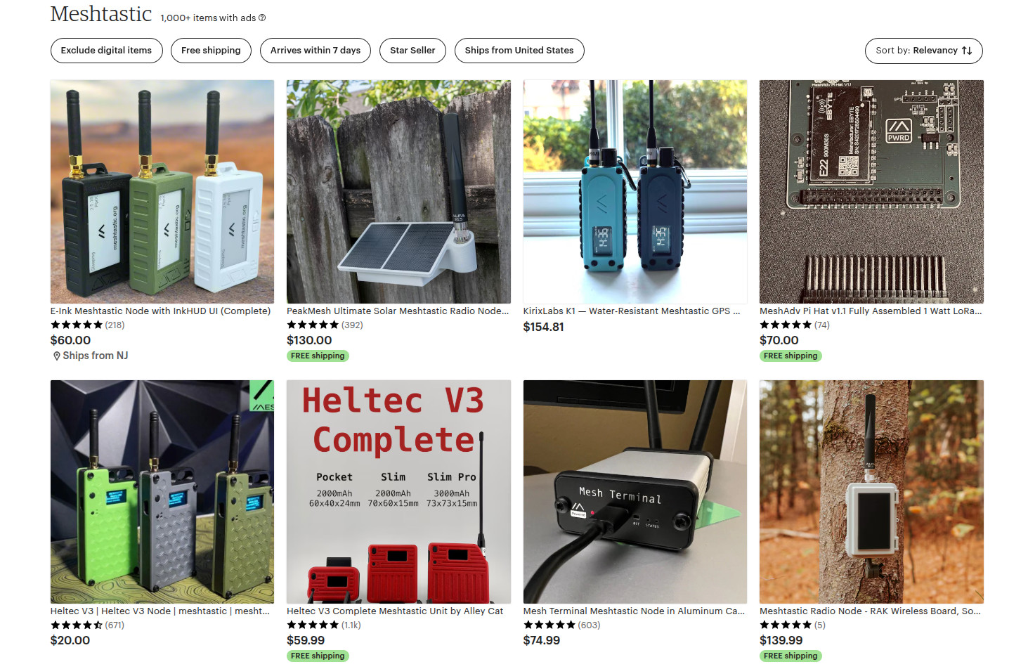
If you’re OK with trading some money for time, there’s a whole world of ready to go Meshtastic devices available online from places like Amazon, AliExpress, and even Etsy for that personal touch. Fans of the retro aesthetic would be hard pressed to find a more stylish way to get on the grid than the Hacker Pager, and if you joined us in Pasadena this year for Hackaday Supercon, you even got to take home a capable Meshtastic device in the form of the Communicator Badge.
Whether you’re looking for a backup communication network in the event of a natural disaster, want to chat with neighbors without a megacorp snooping on your discussion, or are simply curious about radio communications, Meshtastic is a fantastic project to get involved with. If you haven’t taken the plunge already, point your antenna to the sky and see who’s out there, you might be surprised at what you find.
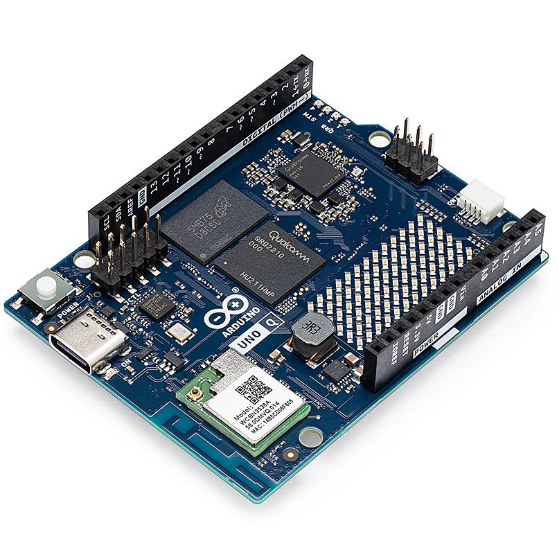
Arduino’s New Overlord
In terms of headlines, the acquisition of Arduino by Qualcomm was a pretty big one for our community. Many a breathless article was written about what this meant for the future of the company. And things only got more frantic a month later, when the new Arduino lawyers updated the website’s Terms and Conditions.
But you didn’t see any articles about that here on Hackaday. The most interesting part of the whole thing to us was the new Arduino Uno Q: an under $50 USD single-board computer that can run Linux while retaining the classic Uno layout. With the cost of Raspberry Pi hardware steadily increasing over the years, some competition on the lower end of the price spectrum is good for everyone.
As for the Qualcomm situation — we’re hackers, not lawyers. Our immediate impression of the new ToS changes was that they only applied to the company’s web services — “The Platform” in the contract — and had no bearing on the core Arduino software and hardware offerings that we’re all familiar with. The company eventually released a blog post explaining more or less the same thing, explaining that evolving privacy requirements for online services meant they had to codify certain best practices, and that their commitment to open source is unwavering.
For now, that’s good enough for us. But the whole debacle does bring to mind a question: if future Arduino software development went closed-source tomorrow, how much of an impact would it really have on the community at this point? Today when somebody talks about doing something with Arduino they are more likely to be talking about the IDE and development environment than one of the company’s microcontroller boards — the licenses for which mean the versions we have now will remain open in perpetuity. The old AVR Arduino code is GPLed, after all, as are the newer cores for microcontrollers like the ESP32 and RP2040, which weren’t written by Arduino anyway. On the software side, we believe that we have nothing to lose.
But Arduino products have also always been open hardware, and we’ve all gained a lot from that. This is where Qualcomm could still upset the applecart, but we don’t see why they would, and they say they won’t. We’ll see in 2026.
The Year of Not-Windows on the Desktop?
The “Year of Linux on the Desktop” is a bit like fusion power, in that no matter how many technical hurdles are cleared, it seems to be perennially just over the horizon. At this point it’s become a meme, so we won’t do the cliché thing and claim that 2025 (or even 2026) is going to finally be the year when Linux breaks out of the server room and becomes a mainstream desktop operating system. But it does seem like something is starting to shift.
That’s due, at least in part, to Microsoft managing to bungle the job so badly with their Windows 11 strategy. In spite of considerable push-back in the tech community over various aspects of the operating system, the Redmond software giant seems hell-bent on getting users upgraded. At the same time, making it a hard requirement that all Windows 11 machines have a Trusted Platform Module means that millions of otherwise perfectly usable computers are left out in the cold.
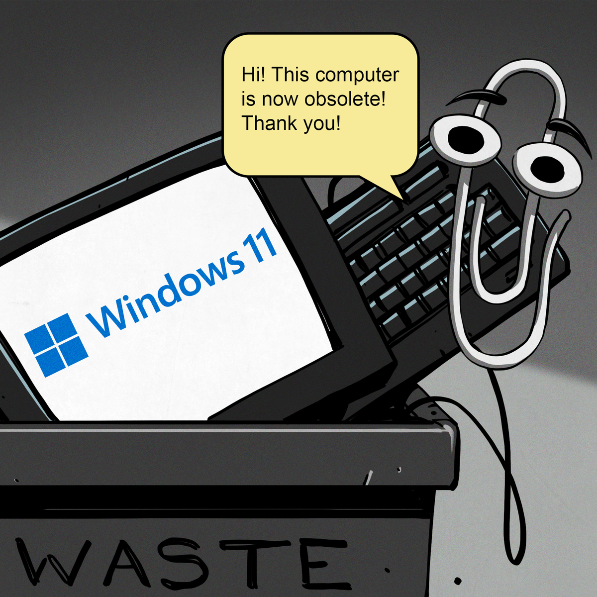 What we’re left with is a whole lot of folks who either are unwilling, or unable, to run Microsoft’s latest operating system. At the same time desktop Linux has never been more accessible, and thanks in large part to the efforts of Valve, it can now run the majority of popular Windows games. That last bit might not seem terribly exciting to folks in our circles, but historically, the difficulty involved in playing AAA games on Linux has kept many a techie from making the switch.
Does that mean everyone is switching over to Linux? Well, no. Certainly Linux is seeing an influx of new users, but for the average person, it’s more likely they’d switch to Mac or pick up a cheap Chromebook if all they want to do is surf the web and use social media.
Of course, there’s an argument to be made that Chromebook users are technically Linux users, even if they don’t know it. But for that matter, you could say anyone running macOS is a BSD user. In that case, perhaps the “Year of *nix” might actually be nigh.
Grandma is 3D Printing in Color
There was a time when desktop 3D printers were made of laser-cut wood, used literal strings instead of belts, and more often then not, came as a kit you had to assemble with whatever assistance you could scrounge up from message boards and IRC channels — and we liked it that way. A few years later, printers were made out of metal and became more reliable, and within a decade or so you could get something like an Ender 3 for a couple hundred bucks on Amazon that more or less worked out of the box. We figured that was as mainstream as 3D printing was likely to get…but we were very wrong.

Today 3D printing is approaching a point where the act of downloading a model, slicing it, and manifesting it into physical form has become, dare we say it, mundane. While we’re not always thrilled with the companies that make them and their approach to things that are important to us like repairability, open development, and privacy, we have to admit that the new breed of printers on the market today are damn good at what they do. Features like automatic calibration and filament run-out sensors, once the sort of capabilities you’d only see on eye-wateringly expensive prosumer machines, have became standard equipment.
While it’s not quite at the point where it’s an expected feature, the ability to print in multiple materials and colors is becoming far more common. Pretty much every printer manufacturer has their own approach, and the prices on compatible machines are falling rapidly. We’re even starting to see printers capable of laying down more exotic materials such as silicone.
Desktop 3D printing still hasn’t reached the sort of widespread adoption that all those early investors would have had us believe in the 2000s, where every home would one day have their own Star Trek style personal replicator. But they are arguably approaching the commonality of something like a table saw or drill press — specialized but affordable and reliable tools that act as a force multiplier rather than a tinkerer’s time sink.
Tariffs Take Their Toll
Finally, we couldn’t end an overview of 2025 without at least mentioning the ongoing tariff situation in the United States. While it hasn’t ground DIY electronics to a halt as some might have feared, it’s certainly had an impact.
A tax on imported components is nothing new. We first ran into that back in 2018, and though it was an annoyance, it didn’t have too much of an impact at the hobbyist scale. When an LED costs 20 cents, even a 100% tariff wouldn’t be much of a hit to the wallet at the scale most of us are operating at. Plus there are domestic, or at least non-Chinese, options for some jellybean components. The surplus market can also help here — you can often find great deals on things like partial reels of SMD capacitors and resistors on eBay if you keep an eye out for them.
We’ve heard more complaints about PCB production than anything. After years of being able to get boards made overseas for literal pennies, seeing a import tax that added at checkout can be quite a shock. But just like the added tax on components, while annoying, it’s not enough to actually keep folks from ordering. Even with the tariffs, the cost of getting a PCB made at OSH Park is going to be much higher than any Chinese board house.
Truth be told, if an import tax on Chinese-made PCBs and components resulted in a boom of affordable domestic alternatives, we’d be all over it. The idea that our little hobby boards needed to cross an ocean just to get to us always seemed unsustainable anyway. It wouldn’t even have to be domestic, there’s an opportunity for countries with a lower import tariff to step in. Instead of having our boards made in China, why not India or Mexico?
But unfortunately, the real-world is more complex than that. Building up those capabilities, either at home or abroad, takes time and money. So while we’d love to see this situation lead to greater competition, we’ve got a feeling that the end result is just more money out of our pockets.
Thanks for Another Year of Hacks
One thing that absolutely didn’t change in 2025 was you — thanks to everyone that makes Hackaday part of their daily routine, we’ve been able to keep the lights on for another year. Everyone here knows how incredibly fortunate we are to have this opportunity, and your ongoing support is never taken for granted.
We’d love to hear what you thought the biggest stories or trends of 2025 were, good and bad. Let us know what lessons you’ll be taking with you into 2026 down below in the comments.


