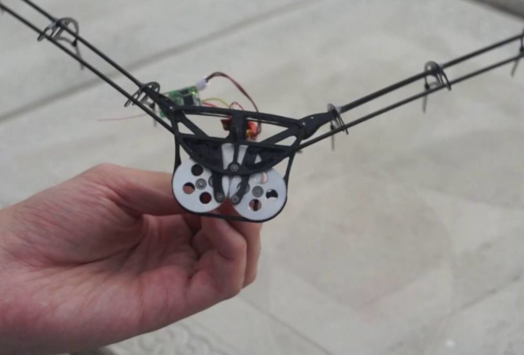
While much less common than quadcopters or airplanes, if you want a device that truly soars like a bird, you need an ornithopter. To help others make their own flying contraption, YouTuber Amperka Cyber Couch is outlining the build process in a video series starting with the one seen below.
Construction is also very well documented in his project write-up, and a clip of it in-flight can be found here. The bionic ‘bird’ uses a BLDC/ESC combination to turn a gearbox that flaps its wings, and an onboard Arduino Nano for control.
Communication is via an MBee 868 wireless module, which links up to an Arduino Uno base station that provides its user interface.
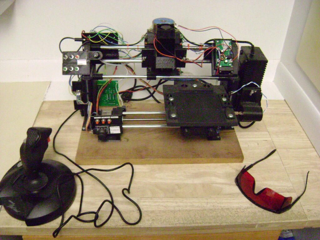
While having a huge workshop with every tool imaginable is ideal, if you have limited funds and/or space, then Mark Miller’s gantry-style machine could be just the thing you need.
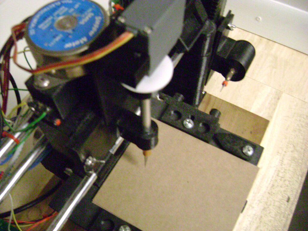
In this setup, the workpiece moves via a stepper motor and a rod system on the bottom, while top support rods accommodate interchangeable tooling.
Tools compatible with the machine (so far) include a 10 watt laser, marker, knife for stencil carving, and a motor/router bit combo for light milling operations. An Arduino is employed for control, while user interface is provided by a series of buttons and a joystick.
Miller even wrote custom software to transform CAD files into sketches that can be directly loaded onto the machine.
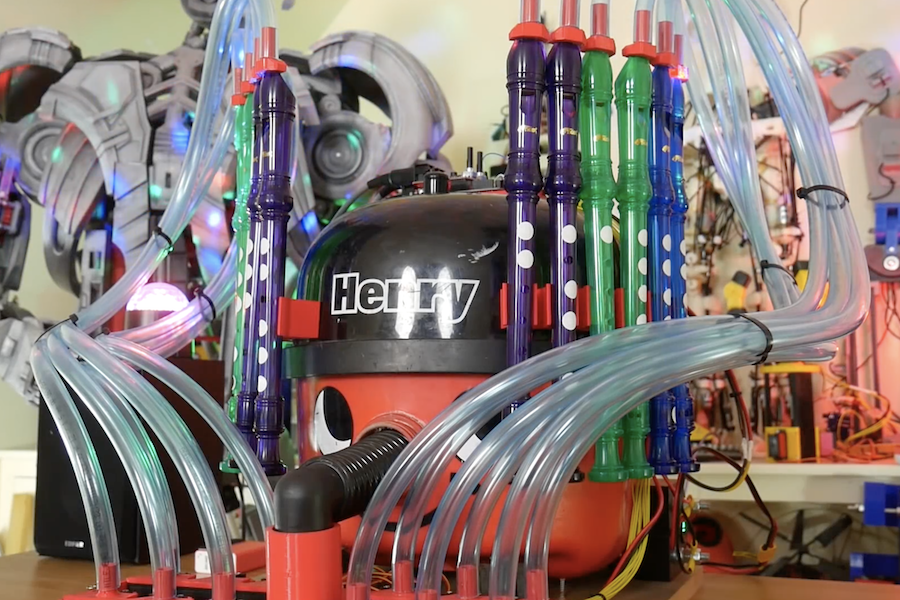
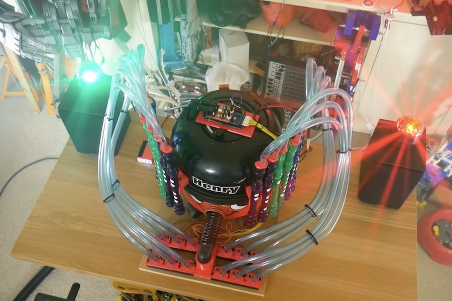
When you see a vacuum cleaner, most people see a useful implement to keep their carpets clean. James Bruton, however, envisioned another use—as a musical instrument. His new project, which made its appearance this year on April Fools’ Day, sucks air through 12 recorders, allowing it to play a full octave and the melody and lead from “Africa” by Toto… or so he’d have you believe!
In reality, power for his instrument comes from a separate Henry Hoover in another room, blowing air through the normally-suction tube of the broken device on the screen. An Arduino Mega, along with a MIDI shield, enables it to open and close air lines to each of the 12 recorders as needed.
Check out how it was made in the first video below and the original fake in the second.
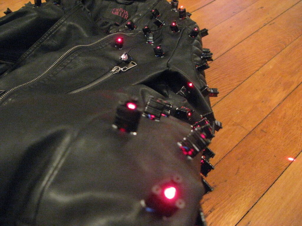
Your leather jacket might look cool, but one thing it’s missing—unless you’re maker “abetusk” or perhaps a Japanese musician—is lasers!
After seeing Yoshii Kazuya’s laser-spiked outfit, ‘tusk decided to create an excellent version of the getup by embedding 128 laser diodes embedded in his own jacket. These lasers are powered by an Arduino Nano, along with a pair of I2C PWM output boards, allowing them to be switched in sets of four.
The lasers can be controlled either by joystick, via a microphone in order to react to sound, or in a looping ‘twinkle’ pattern.
More information on the project is available in this write-up as well as on GitHub, which includes Arduino code and other files needed to build your own.
After seeing Wei Chieh Shi’s laser jacket design, I wanted to create my own. These instructions show how to modify a jacket to add laser diodes and control them electronically to produce different laser light patterns. The laser diodes give the jacket an appearance of being “spiky”, like having metal spikes but with red laser light. The effect is especially striking in environments with fog or smoke as the laser light path shows a trail from where it originates.
The concept and execution is relatively simple but care has to be taken to make sure that the electronics, wiring and other aspects of the jacket don’t fail when in use. Much of the subtlety and complexity of the project is providing proper wire routing and making sure that strain relief for the electronics and connections is provided so that it’s resilient under normal wear.
Assuming the basic parts are available (soldering iron, multimeter, wire strippers, laser cutter, etc.) I would estimate that this project is about $300 in raw materials and about 20 hours worth of labor.
Depending on the battery used, the jacket can operate for about an hour or two continuously. Spare batteries can be carried around and used to replace the depleted batteries if need be.
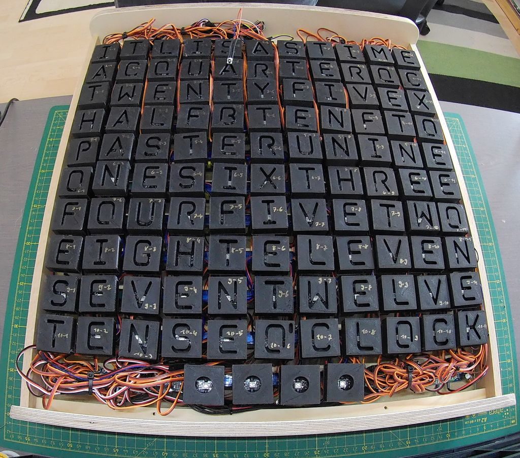
Word clocks normally use an array of lights to show the time, and although this project does use lights, how it works is much different than others.
LEDs for the device are hidden behind a thin layer of PVC, while 114 tiny SG90 servos move the lights and their 3D-printed frames back and forth. The result is a stunning display where the time is spelled out by the appropriate letters. These progressively come into focus, setting them apart from inactive letters which appear to fade into the background.
An Arduino Nano drives the assembly, along with an infrared controller setup and an RTC module for accurate timekeeping. A demo can be seen in the first video below, and the very involved build process is highlighted in the second clip.
What has 114 LEDs and is always running? As you may know the answer is a word clock. What has 114 LEDs + 114 servos and is always moving? The answer is this servo controlled word clock.
For this project I teamed up with a friend of mine which turned out to be a must because of the large effort of this build. In addition, my electronic and his mechanical skillset complemented each other quite well. The idea for this adaptation of the popular word clock came to us while we were making a regular one as Christmas gift. There, we noticed that it is also possible to project the letters from the back onto a white sheet of paper. At the time this was only a workaround solution to hide our crappy craftsmanship since we ended up with a lot of bubbles while attaching a vinyl sticker with the letters to the back of a glass plate. We then noticed that one can achieve interesting effects when bending the sheet of paper since the letters change size and become blurred. This made us come up with the idea to make a word clock where the letters are projected from the back onto a screen and can be moved back and forth to change the size of the projected image. At first we were a bit reluctant to build this project because of the costs and effort it takes when you want to move each of the 114 letters individually. So we tossed with the idea to make a version where just every word that is used to display the time can be moved back and forth. However, after seeing that the Epilog contest was coming up on Instructables asking for epic projects, and also after finding relatively cheap servo motors, we decided to go all the way and make a proper version where each letter is individually controlled by a servo
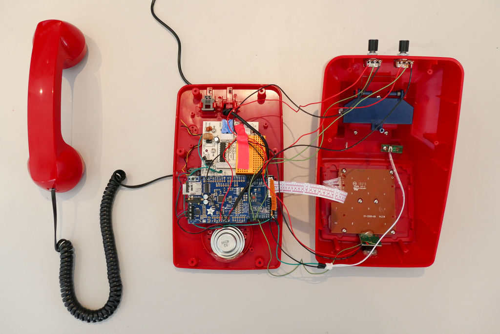
If you’ve ever thought that your life needs a little more hold music in it, then this Greatest Holdies phone from FuzzyWobble could be just the thing.
The heavily modified device uses the shell of an old-style desk phone, but adds an Arduino Mega, a Music Maker Shield, and an ultrasonic rangefinder for “enhanced” abilities.
Now, when someone comes near the phone, it rings automatically, treating the person curious enough to pick it up to a selection of hold music. Users can choose the tune playing via the phone’s keypad, which is wired into the Arduino, along with the original headset switch that detects when the phone has been picked up.
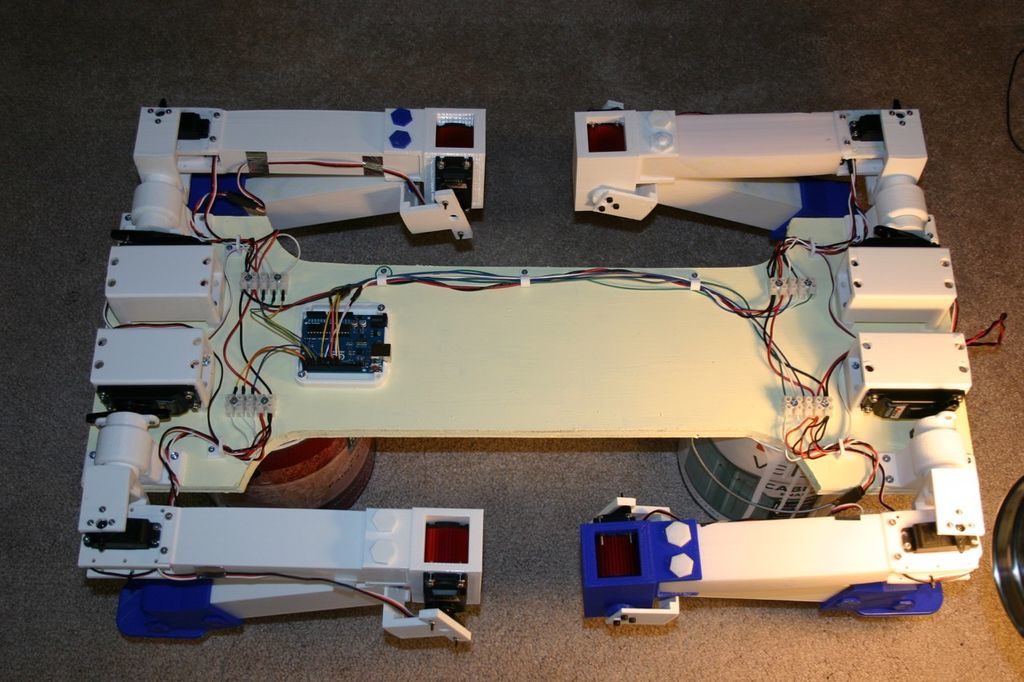
Would you like a dog? Would you like a robot dog? If so, then this build by Michael Rigsby could be a great starting point.
Rigbsy’s robotic pet features four servo-driven legs, with two-axis shoulder movement, as well as an articulated knee joint. As seen in the video below, it’s capable of picking itself up off the ground, and can then walk using a slow side-to-side gait.
An Arduino Uno uses the majority of its I/O pins to control the legs, and as of now, it travels forward with no directional control or sensor input.
Instructions for the project, along code and 3D print files, are available in Rigsby’s write-up.
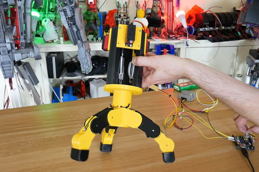
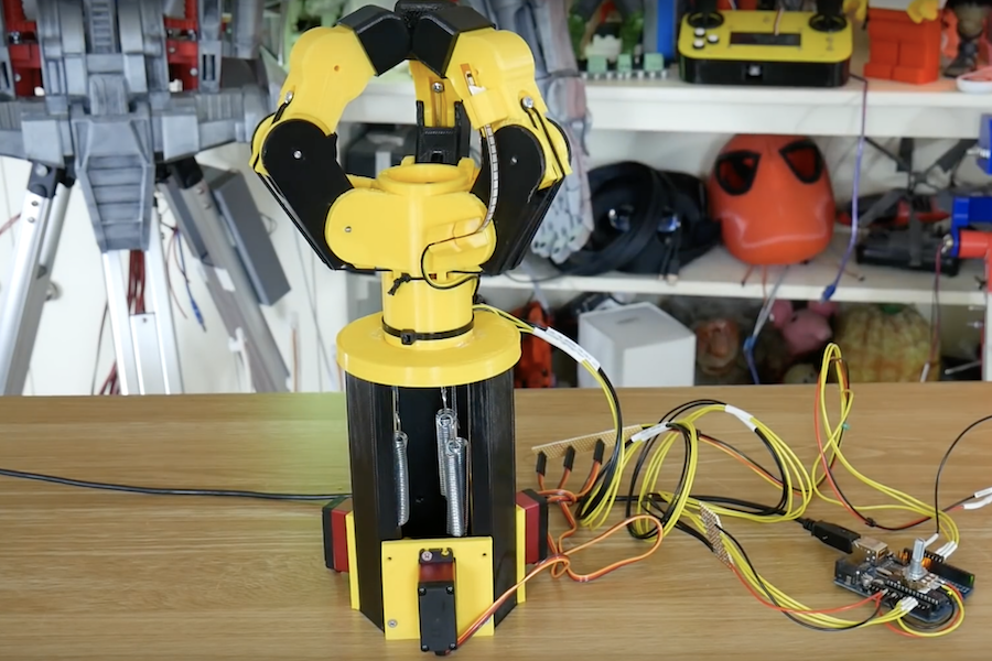
In a variety of robotic situations, you’ll need some sort of gripper. In this project, James Bruton attempts to create a force-controlled, three-fingered assembly using an Arduino Uno along with a trio of servos.
Instead of directly controlling the grip fingers, the 3D-printed device is held open with bungee cables. When it’s time to clamp everything down, the servos wind up the cables attached to the inside of the fingers, similar to how human tendons work.
To correlate servo inputs to grip force, he uses a series of springs to allow some amount of compliance, as well as flex sensors attached to the fingers themselves to measure the resulting positions. Arduino code for the build is available here.
The AbleChair by Advanced Fitness Components is nominally a wheelchair, but it’s capable of so much more.
The versatile wheelchair’s enhanced abilities include elevating the user to standing height or lowering for easy transfers. Additionally, the seating assembly can be flattened and positioned parallel to the ground, and even vertically as needed. This vertical position allows it to act as a gait training aid for those that are learning to walk, and the variety of positions has a number of health benefits.
The system itself is powered by Arduino along with brushless motors and sensors, while a joystick, touchscreen, and an Android app are used for control.
Riding a bicycle can be a great way to get around, and/or even to get some needed exercise. When you mix in automobile or foot traffic, though, things get a bit more complicated. This could be blamed, in part, on the fact that bikes don’t have the same running lights, turn or brake signals as motorized vehicles.
To address this problem, BLINK!’s patented Integrated Lighting System (iLS) has been designed to provide a visible communication solution that’s easily understandable by other road users.
This custom saddle—which was prototyped using an ATmega328P-based Arduino— features lighting for 270º visibility, and brightens automatically for braking when deceleration is detected. In addition, iLS includes a pair of remotely activated turn signals. This allows the rider to indicate direction changes without removing his or her hand from the handlebars to awkwardly point.
BLINK! has been embedded into a wide range of saddles and installation should be fairly straightforward. Not only will it certainly help enhance road safety, iLS will look fantastic while doing so.