Tertiarm - low cost, 3d printed robot arm based on Ikea lamp
Primary image

What does it do?
Move things, push buttons, etc.
Cost to build
Embedded video
Finished project
Complete


[Please excuse my English]
[Please excuse my English]
[Please excuse my English]

[Please excuse my English]
If you haven’t jumped on the ESP8266 bandwagon yet, it might be a good time to get started. If you can program an Arduino you have pretty much all of the skills you’ll need to get an ESP8266 up and running. And, if you need a good idea for a project to build with one of these WiFi miracle chips, look no further than [Ben Buxton]’s dated, but awesome, NTP clock.
While the ESP8266 started out as an inexpensive, reliable way to get WiFi capability on essentially anything (and paving the way for a plethora of Internet of Things projects), it was quickly hacked to become a fully programmable development board that can stand on its own. To that end, [Ben] has recognized its capability to run a very minimalistic NTP clock. The standard C++/Arduino environment is available, so he didn’t have to learn any new skills. The parts list is stripped down as well: besides the ESP8266, there’s little more than the four-part seven-segment display. There’s even an Arudino library for these chips that [Ben] made great use of. From there, it’s just a matter of wiring it all up and syncing it with an NTP server.
While it’s not the most involved hack ever, it’s good to be reminded that these chips are cheap and readily available for literally anything that you could imagine. If you haven’t started yet, there’s no reason not to. You can use them to control something like an irrigation system, or if you’re even more adventurous, they can run a 3D printer, too.
Thanks [Itay] for the tip!


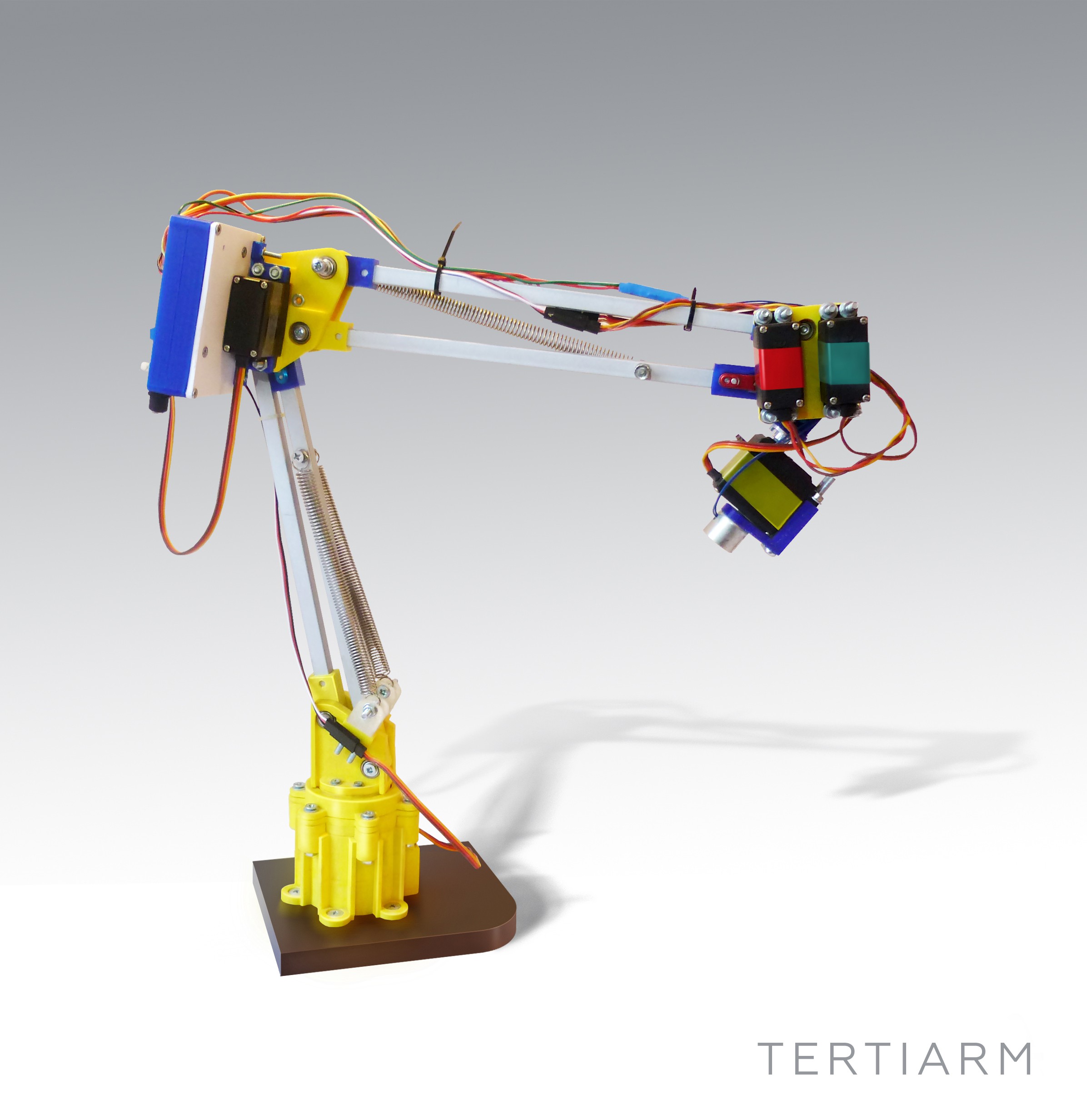
Last fall, I grabbed a robot arm from Robot Geeks when they were on sale at Thanksgiving. The arm uses servos to rotate the base and move the joints and gripper. These work well enough but I found one aspect of the arm frustrating. When you apply power, the software commands the servos to move to home position. The movement is sufficiently violent it can cause the entire arm to jump.
This jump occurs because there is no position feedback to the Arduino controller leaving it unable to know the positions of the arm’s servos and move them slowly to home. I pondered how to add this feedback using sensors, imposing the limitation that they couldn’t be large or require replacing existing parts. I decided to try adding accelerometers on each arm section.
Accelerometers, being affected by gravity when on a planet, provide an absolute reference because they always report the direction of down. With an accelerometer I can calculate the angle of an arm section with respect to the direction of gravitational acceleration.
Before discussing the accelerometers, take a look at the picture of the arm. An accelerometer would be added to each section of the arm between the controlling servos.
Gravity tugs everything toward the center of the mass of the Earth. It is a force that creates an acceleration exactly just like what you feel when a vehicle begins to move or stop. The force of gravity creates an acceleration of 1 g which is 9.8 m/s2 or 32.15 ft/s2. An accelerometer measures this force.
Integrated circuit accelerometers are inexpensive and small devices readily usable by hackers. One reason they are inexpensive is the high demand for them in smart phones. These small devices are based on etching mechanical structures within the integrated circuit using a technology called MEMS (Microelectromechanical systems).
One design for a MEMS accelerometer is basically a variable capacitor. One plate is fixed and the other mounted some distance away on a spring suspension. When the device is accelerated the suspended plate moves closer or further away from the fixed plate, changing the capacitance. Another uses piezo-resistive material to measure the stress on an arm caused by acceleration.
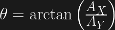
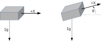 A single axis accelerometer measures acceleration in only one direction. If positioned so the direction is up and down it will measure the force of gravity but will not detect horizontal acceleration. When the device is tilted between horizontal and vertical the force of gravity is only partially affecting the measurement. This provides the ability to measure the angle of the device with the direction of gravity. The acceleration felt along the tilted axis, for a tilt angle can be calculated by:
Knowing the output of the accelerometer we can determine the angle by taking the inverse sine, the arc sine, of the output:
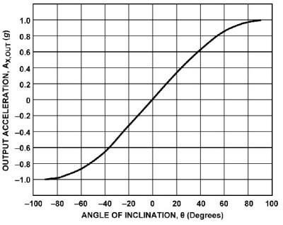
If you rotate a single axis device through 360° the output is a sine wave. Start with the device outputting zero and consider that 0°. As it rotates, the output is 1 when the angle is 90° and back to zero at 180°. Continuing the rotation, the output becomes -1 at 270°, or -90°, degrees and back to zero at 360°, or 0°.
Notice on the chart that between -60° and 60° the output is nearly linear. This is the best orientation for measuring inclination. Increases in inclination are not as accurate on the other portions of the curve. Also notice that the same output is generated for 45° and 135° (90° + 45°) creating an ambiguity. With a single axis you cannot determine which of those angles is measured.

Putting two accelerometers at a right angle to one another creates a 2-axis device which solves the ambiguity problem. As the device is rotated through 360° the outputs are 90° out of phase, the same relationship as the sine and cosine. By combining the measurements there is a unique solution for every angle throughout 360°. The acceleration due to gravity at each angle is given by:
which leads to calculating the angle by:
Actually, one more step is needed to determine the sign of the angle. This requires examining the sign of the values for the X and Y axis. It isn’t necessary to go into this here because a standard programming function handles this automatically.
The orientation of a quadcopter requires a 3-axis accelerometer. The calculations for the three spherical angles combine all three inputs for their results. You’ll need to study this carefully because the standard trigonometric equations can cause anomalies when the quadcopter flips.
Accelerometers are easily obtained and relatively cheap. You can find them mounted on breakout boards with voltage regulators and all the supporting circuits from the usual vendors. They are available for 1 to 3 axis, various amounts of g force, and providing either analog or digital outputs. Analog devices need an analog input for each axis being measured. Digital outputs use I2C or SPI buses for communications. I decided to use analog devices because digital units typically only allow two addresses and the arm needs three devices, one for each section.
The robot arm uses an Arduino board so there are at least 6 analog inputs. The original board was a Robot Geek Geekduino, their version of the Arduino Duemilanove, with 8 analog inputs. Unfortunately, when working with the arm I broke the USB connector so switched to a Uno equivalent having only 6 inputs.
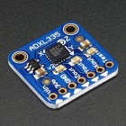 My choice for accelerometer is a 3-axis, ±3 g accelerometer breakout from Adafruit, their ADXL335. It has one analog output for each axis. Since I’m measuring three joints that means three boards which adds up to 9 analog outputs.

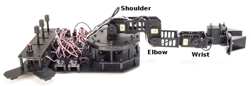
Because of the geometry of the arm, however, I only need 5 inputs for these three joints. The shoulder joint only moves from 0° to 180°. This can be handled by a single axis accelerometer by mounting it to read acceleration of 1 g for 0° and -1g for 180°. That provides a unique output for the necessary angles. The elbow and wrist joints each require two inputs. The third input is not needed because their motion is constrained to moving within the vertical plane of the arm.
The next issue is the frame of reference. This is a standard problem in robotics work. Early in a project, a global frame of reference is decided upon. This sets the origin for the coordinate system that the robot will follow and the direction of the three axes, usually specified as X, Y, and Z. For the arm, X is straight forward, Y is to the left, and Z is straight up. The zero point is the base of the shoulder. This also defines a global frame for rotation of the arms limbs with zero degrees also toward the front.
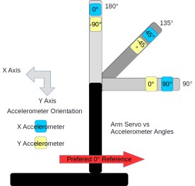
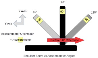
Sensors and controllers each have their own frame of reference. Any differences among these devices and the global frame need to be resolved in software. The shoulder servo’s frame of reference is 0° at the back of the arm and 180° at the front, a clockwise rotation. This is the reverse of the global frame. The elbow servo worked the opposite with a counter-clockwise rotation putting 180° straight up and 90° straight out when the shoulder was vertical. It is 90° off from the global frame of reference.
Sensors also have their own frame of reference. The Y-axis accelerometer measuring the shoulder orientation worked counter-clockwise. Both axis on the accelerometers measuring the elbow worked in the clock-wise direction. This may seem strange but it’s because of the different mounting orientations of the sensors.
The actual code is straightforward once the frame of references are sorted out. A single axis is read from the analog input and its angle calculated with:
const int shouldery = shoulderAnalogY.read();
float shoulder_angle = degrees(asin(shouldery_value / 100.0));
The read() method scales the raw analog input values so ±1g is represented as ±100. The input to asin() is divided by 100.0 to convert to the actual g value. That suffices for the shoulder angle.
The elbow and wrist angles use values from two axis and the calculation is:
const int elbowx = elbowAnalogX.read();
const int elbowy = elbowAnalogY.read();
float elbow_angle = degrees(atan2(-elbowy, elbowx));
The atan2() function is a special version of the arc tangent calculation. It examines the signs of the input value to determine the quadrant of the angle to set the appropriate sign on its result. The negative sign on the elbowy is needed to set the appropriate quadrant. There’s the frame of reference issue, again.
Adding the accelerometers solved the startup lurching problem well enough. Whether the accelerometers can be used for other purposes remains to be seen.
The accuracy of the angle measurements is not good. In part this is due to using a device that with a +/- 3 g range to measure 1/3 of the devices range, 1 g. The device outputs 0 to 3.3 volts while the Arduino is sampling for 5 volts, again losing accuracy. This might be improved by using an Arduino based on 3.3 volts. I have a couple Dues on hand so might try them. The Uno also provides for adjusting the reference voltage for analog inputs so setting it to 3.3 volts might help.
The analog values need to be calibrated with some care. Each accelerometer outputs slightly different values. Calibration requires measuring the outputs for 1 and -1 g for each axis, recording the values, and using them to scale the voltage input to acceleration. This calibration is not accurate given the other problems with the analog inputs.
Another problem is the mounting of the accelerometers on the arm’s sections. The alignment of the boards with the sections of the arm is not perfect. When the servo is positioned at 90° the accelerometer doesn’t necessarily sit at 90° with respect to the center of the earth. Of course, the servos are not that precise, either. They do not always arrive at the same position, especially when approaching from different directions. Another goal for this project was to use the accelerometer information to more precisely position the servos.
I guess I have to think about this project a bit more, including deciding what I actually want to accomplish with the arm. But then, just saying you have a robotic arm is a terrific hacking cred.


At Arduino Day, I talked about a project I and my collaborators have been working on to bring machine learning to the maker community. Machine learning is a technique for teaching software to recognize patterns using data, e.g. for recognizing spam emails or recommending related products. Our ESP (Example-based Sensor Predictions) software recognizes patterns in real-time sensor data, like gestures made with an accelerometer or sounds recorded by a microphone. The machine learning algorithms that power this pattern recognition are specified in Arduino-like code, while the recording and tuning of example sensor data is done in an interactive graphical interface. We’re working on building up a library of code examples for different applications so that Arduino users can easily apply machine learning to a broad range of problems.
The project is a part of my research at the University of California, Berkeley and is being done in collaboration with Ben Zhang, Audrey Leung, and my advisor Björn Hartmann. We’re building on the Gesture Recognition Toolkit (GRT) and openFrameworks. The software is still rough (and Mac only for now) but we’d welcome your feedback. Installations instructions are on our GitHub project page. Please report issues on GitHub.
Our project is part of a broader wave of projects aimed at helping electronics hobbyists make more sophisticated use of sensors in their interactive projects. Also building on the GRT is ml-lib, a machine learning toolkit for Max and Pure Data. Another project in a similar vein is the Wekinator, which is featured in a free online course on machine learning for musicians and artists. Rebecca Fiebrink, the creator of Wekinator, recently participated in a panel on machine learning in the arts and taught a workshop (with Phoenix Perry) at Resonate ’16. For non-real time applications, many people use scikit-learn, a set of Python tools. There’s also a wide range of related research from the academic community, which we survey on our project wiki.
For a high-level overview, check out this visual introduction to machine learning. For a thorough introduction, there are courses on machine learning from coursera and from udacity, among others. If you’re interested in a more arts- and design-focused approach, check out alt-AI, happening in NYC next month.
If you’d like to start experimenting with machine learning and sensors, an excellent place to get started is the built-in accelerometer and gyroscope on the Arduino or Genuino 101. With our ESP system, you can use these sensors to detect gestures and incorporate them into your interactive projects!

Driven by the sudden longing for a personal Delta Robot I found myself building one.