Posts with «attiny» label

ATtiny Does 170×240 VGA With 8 Colors

The Arduino is a popular microcontroller platform for getting stuff done quickly: it’s widely available, there’s a wealth of online resources, and it’s a ready-to-use prototyping platform. On the opposite end of the spectrum, if you want to enjoy programming every bit of the microcontroller’s flash ROM, you can start with an arbitrarily tight resource constraint and see how far you can push it. [lucas]’s demo that can output VGA and stereo audio on an eight-pin DIP microcontroller is a little bit more amazing than just blinking an LED.

[lucas] is using an ATtiny85, the larger of the ATtiny series of microcontrollers. After connecting the required clock signal to the microcontroller to get the 25.175 Mhz signal required by VGA, he was left with only four pins to handle the four-colors and stereo audio. This is accomplished essentially by sending audio out at a time when the VGA monitor wouldn’t be expecting a signal (and [lucas] does a great job explaining this process on his project page). He programmed the video core in assembly which helps to optimize the program, and only used passive components aside from the clock and the microcontroller.

Be sure to check out the video after the break to see how a processor with only 512 bytes of RAM can output an image that would require over 40 KB. It’s a true testament to how far you can push these processors if you’re determined. We’ve also seen these chips do over-the-air NTSC, bluetooth, and even Ethernet.


Filed under: ATtiny Hacks

New dimmer software

Based on the success of the stroboscope software, I rewrote the dimmer software for my desk lamp (see LED lamp projects for more about the lamps).  The new software provides smoother control of the light levels (having 256 levels plus off, rather than 63 levels plus off) and now has a 256:1 brightness range rather than the approximately 256:6 range of the previous code.

I removed a lot of the general-purpose crap that was inherited from core13 (which was in turn stripped down from the Arduino core software).  I did not get rid of all of core13, so I could probably take out another 50–100 bytes, but the code is down to 222 bytes (and the ATtiny13A has 1kB of flash, so I’m way below the limit).

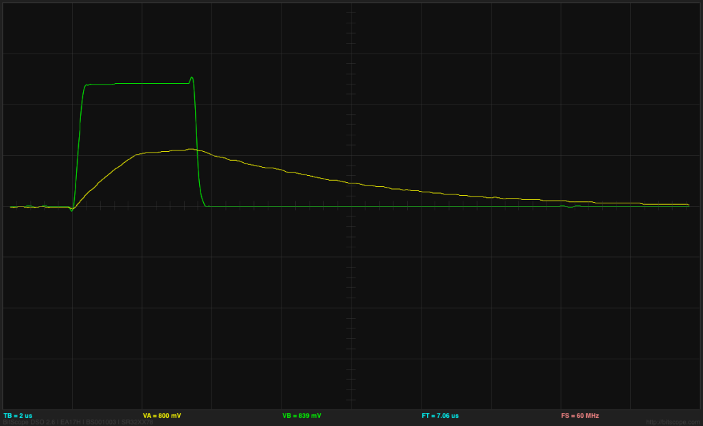
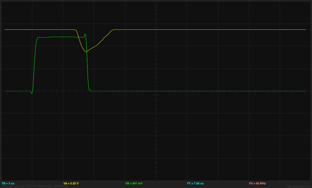
The actual brightness range of the new dimmer is a bit more than 256:1, because on the shortest pulse the FET doesn’t turn all the way on.  The pulse duration from the ATtiny13A is approximately 3.4µs times the brightness level (9.6MHz clock divided down by 4 and by 8), but I had deliberately slowed the FET transitions by adding a series resistor to the gate, so that nFET doesn’t finish turning on for 5.2µs (as judged by the end of the Miller plateau on the gate).  So at the lowest brightness level, the nFET does not turn all the way on and the voltage on the drain only gets down to 3.5V, which leaves 5.5V across the LED board—enough to turn on the LED, but with only about 10mA, not 118mA. At this low level, the LEDs sometimes flicker, perhaps as a result of some thermal feedback effects. The all flicker together, so the effect is probably in the dimmer’s nFET, not on the LED boards.

ATtiny output (green) and gate voltage (yellow) at 2V/division and 2µs/division for the shortest pulse length. The gate voltage has not quite reached the end of the Miller plateau before being discharged again.

ATtiny output (green) and drain voltage (yellow) at 2V/division and 2µs/division for the shortest pulse length. The BitScope BS-10 oscilloscope clips the voltage to 5.5V—it actually goes to 9V.

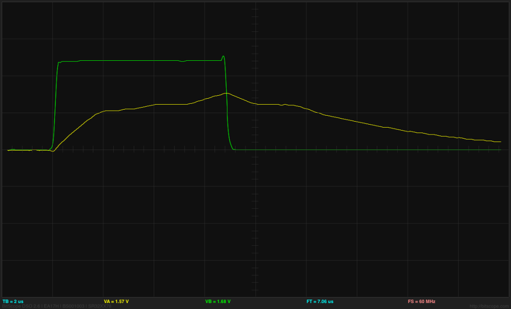
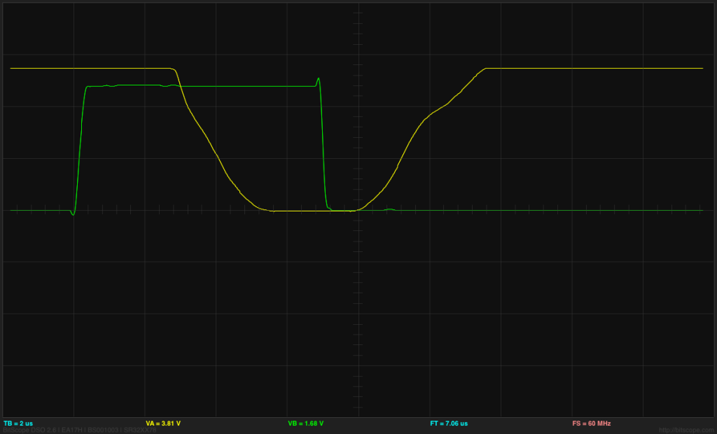
At the next brightness level, the drain voltage does drop to 0V for at least 2.4µs and stays low enough for the LED board to be at maximum current (below 2.5V) for at least 5.5µs.  There is an enormous difference in brightness between length 2 and length 1 pulses (more like 1:20 than 1:2), because of the low current for pulse length 1, but for length 2 and longer the steps in brightness are pretty much as one would expect from the pulse lengths.

ATtiny output (green) and gate voltage (yellow) at 2V/division and 2µs/division for the shortest pulse length. The gate voltage has gone past the end of the Miller plateau and started charging past that point. The Miller plateau is also visible on the discharge as the nFET turns off.

ATtiny output (green) and drain voltage (yellow) at 2V/division and 2µs/division for the second shortest pulse length. The BitScope BS-10 oscilloscope clips the voltage to 5.5V—it actually goes to 9V.
The longer pulses allow the nFET to turn on fully.

The conversion from the linear 10-bit analog-to-digital reading (0–1023) to pulse lengths is done by the following method:

expon = ADC>>7
frac = 0x80 + (ADC & 0x7f)
pulse_len = ADC < 0x20? 0:  ADC < 0x40? 1: 1+ (frac>> (7-expon))

The stepwise nature of the brightness at low levels is apparent in a plot of the conversion function:

The steps in brightness are quite visible at the low end, but after the first 10 steps, the differences are small enough not to be easily noticed.

Overall, I’m pleased with the rework of the dimmer code. I’ll probably have to solder up another of the dimmer boards this summer, since I’ll want one for the light fixture that I haven’t started building yet and one for the Halloween stroboscope.


Filed under: Uncategorized Tagged: Arduino, ATtiny, BitScope, dimmable LED lamps, lamp, Miller plateau

LED strobe using dimmer board

In the evenings this week, I soldered up another PWM controller for the LED lamp projects, and programmed it with the ISP cable I made.  The intent was to use this dimmer either with the breakfast-room lighting fixture (which I’ve not made yet) or reprogram it to act as a strobe rather than a dimmer, to replace the Xenon-tube-based Velleman strobe kit that failed last Thanksgiving.

This project took me much longer than expected, because of stupid mistakes I made:

  • I forgot that there was a silkscreen error on the dimmer boards that I had designed.  The outline for the voltage regulator is flipped, because I had not noticed when reading the spec sheet shows the device from the bottom—I’m used to chip views being from the top.  This is the second time that I’ve soldered a voltage regulator on one of the boards backwards, and had to cut it off and replace it with a new one.  I guess I’d better take a permanent felt-tip marker and draw the correct orientation on the remaining boards, so that I don’t make that mistake a third time.
  • When playing with new code for the strobe, refamiliarizing myself with the ATtiny13A processor, I changed the prescaling on the system clock from the default 1.2MHz down to about 75kHz.  What I had not realized is that the on-chip clock is used during the reprogramming also, and the Arduino ISP is not set up for slowly clocked chips.  I found code for TinyISP, which has code for 128kHz clocks, but even when I modified it for 75kHz clocks I couldn’t reprogram the chip (always getting the “Yikes! invalid device signature” message with a signature of 0). Eventually, I gave up, unsoldered the ATtiny13A and put in a new one.  I’ll be very careful in future not to slow down the system clock so much.
  • I got the strobe working this morning, but when I looked at the output pin that was driving the FET gate, it was only going up to 1.3V, not 5V, and the pulse was much longer than I expected.  This mystified me for a while, but I finally realized that I had forgotten to turn the pin on as an output, so I was driving the output just through the built-in pullup resistor, resulting in a very large RC time constant.  The flat top I was seeing on the pulse was probably the Miller plateau.  Enabling the output pin correctly got me back to crisp 5V pulses of the designed duration.
  • The designed duration for the pulses was a bit too short, resulting in a somewhat dimmer than desired flash.  Lengthening the pulse to 1ms was fine for the slow strobes, but at high flash rates the strobe got too bright. So I reprogrammed the flashes so that the on-time was 1/64th of the off-time, but with a maximum on-time of 1.6ms. (I also tried on=off/128 with a maximum of 1ms, but I liked the 1/64 better).

I timed the strobe pulses from the board (looking at the output of the ATtiny13A pin 6, which is also connected to the MISO pin of the ISP header, so is easy to connect a jumper wire to) with PteroDAQ (through a voltage divider, to drop the voltage from 5V to 2.75V).  By triggering the PteroDAQ on edges of the signal, and averaging many measurements, I got very precise timing measurements:

setup on-time off-time
slowest setting, 1:64 1.63745ms 1.52372s
fastest setting, 1:64 104.958µs 6.98761ms
slowest setting, 1:128 955.277µs 1.55881s
fastest setting, 1:128 51.3123µs 6.99286ms

The difference in the “slowest” settings is probably just from my inability to set the knob identically—it has to be just above a threshold below which the strobe doesn’t flash at all. In any case, I have a period from 7.1ms (141Hz) to 1.525s (0.6556Hz), which is a pretty useful range.  I also made the range very smooth, by taking the 10-bit ADC range and converting it to this 215:1 range sort of exponentially with just a few instructions:

if adc<40, then OFF
exp = adc >> 7
frac = 0xff - (adc & 0x7f)
on_time = (frac << 8) >> exp
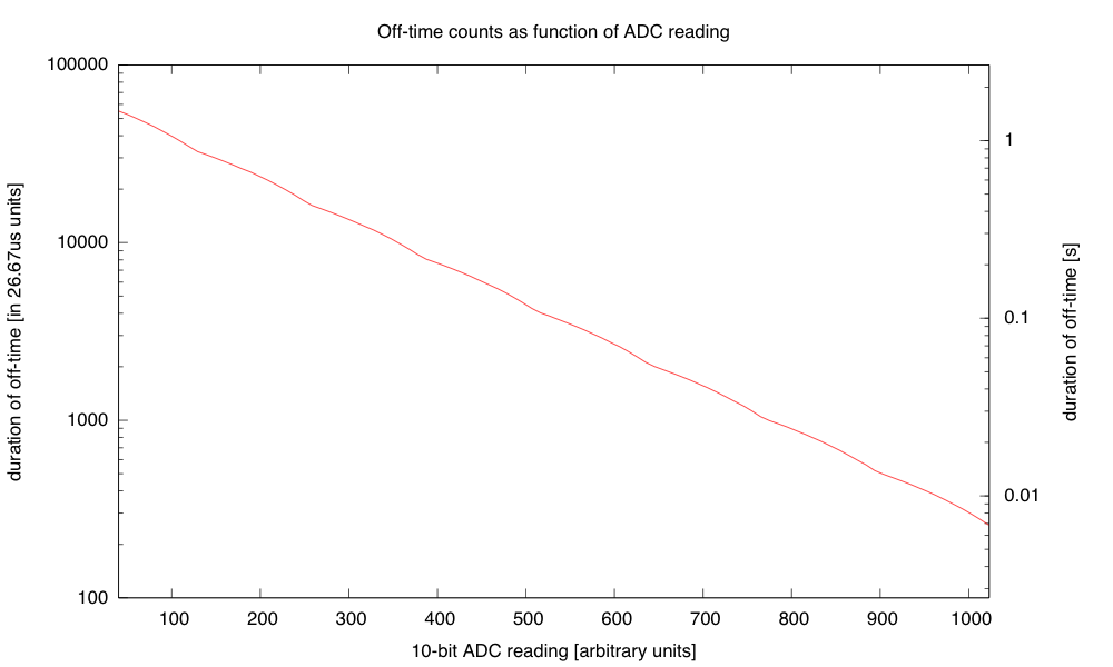
The tiny number of instructions provides a surprisingly smooth and strictly decreasing approximation to the desired exponential.

The transition is smooth because every time an increment increases the exponent, the frac part is doubled (from 0x80 to 0xff).I use a 16-bit word for the on_time and count it down with an interrupt once every 26.67µs (256 of the approximately 9.6MHz clock ticks). I think that I’ll do a similar thing for controlling the duty cycle of the dimmer, rather than the table of bytes that I currently use, though the duty cycle is limited to a single byte, so I’ll only have 256 levels, and not 1024, and I’ll want the duty cycle to increase exponentially, rather than decreasing, but those are easy fixes.

I also reduced the size of the program in flash, by getting rid of some of the overly general code from core13 and just manipulating the peripheral control registers directly.  I didn’t need to do this, as the ATtiny13A has 1kB of flash, but I got down to 364 bytes (and could probably strip out another 50–100 by getting rid of even more of core13).  The old dimmer code, which doesn’t have much more to do, currently takes 806 bytes, so I might try tightening that up tomorrow.

I also tried powering the strobe off a 9V battery.  The LED board takes about 117mA when turned on (see LED board I-vs-V curve), and if I keep the duty cycle below 1.5%, then the average current is dominated by the ATtiny13A’s worst-case 6mA current, and the total current for the board is probably less than 8mA.  According to Duracell’s data sheet for their 9V alkaline battery, I should be able to get about 50 hours of life before the voltage drops below 6.7V (at which point the LED board no longer maintains the constant current, but I could run the strobe a bit longer getting dimmer).  The 6.7V is also about the voltage where the LDO voltage regulator starts being unable to supply 5V to the ATtiny13A, though that is less of a bottleneck, as the chip can run with the 9.6MHz internal clock down to 3V with no problems.

The battery does not have to provide a full 117mA for the pulses, as there is a 470μF polymer electrolytic capacitor on the dimmer board.  Delivering 117mA for 1.6ms is only 187μC, so the voltage on the capacitor would dip at most 0.4V during the pulse, even without the battery.  The 9V battery has an internal resistance of 2Ω–4Ω, so it could provide 117mA with about a 0.35V drop, so the capacitor isn’t really necessary for one LED board.  It probably increases the efficiency slightly, as the I2R power loss in the internal resistor is reduced if the current is spread out (half the current for twice as long is only half the I2R loss).

I could put more LED boards on the strobe, as the dimmer is designed to handle 5A or more, but battery  operation would limit me to about 10 boards before the voltage drop was large enough to cause problems for the current regulation.  One LED board is bright enough for a Halloween pumpkin, but I could run wires between pumpkins to power several off the same controller.  (I could also keep the controller in the house, powered by a wall wart, and run wires out to the LED boards—I could then power 40 or 50 LED boards off the strobe, though I’d have to watch out for IR drop in the wiring.)

I might try wiring up 10 boards tomorrow, and see whether a battery really can power that many.


Filed under: Uncategorized Tagged: Arduino, Arduino as ISP, ATtiny, dimmable LED lamps, lamp, strobe, stroboscope

Arduino as ISP

For the LED lamp projects, I’ve been using ATtiny13A chips for the dimmer board, programmed with the Arduino IDE and an Arduino board as an In-System Programmer (ISP).  The Arduino code is too big for an ATtiny, so I’ve been using a version of the core13 stripped-down system.

I got rather tired of wiring up the 8 wires for the ISP, checking to make sure that each one was correct.  What I wanted to do was just plug in a standard 8-pin cable from the Arduino board to the ATtiny board, but the ISP header on the Arduino board has the Arduino reset line, not the reset line that has to go to the ATtiny board.

I decided to modify a standard cable to do the right thing, separating the reset line from the rest. The reset line is on pin 7, so on a standard ribbon cable, it is the seventh of the eight wires.

First I carefully cut wire 7 near one of the plugs with a razor knife, peeled it back and spliced on another piece of stranded wire:

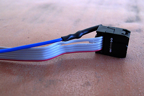
The blue wire and wire 7 of the ribbon cable were soldered together and covered with heat-shrink tubing.

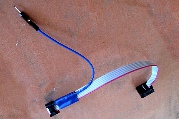
I taped the soldered joint to rest of the ribbon cable for strain relief, and added a crimp-on female header at the other end. (I prefer female crimp-on headers, because they are more versatile than male pin—I can stick in a double-ended male header pin to convert them to male connectors when needed.)

The electrical tape stabilizes the splice and the crimp-on female header allows connecting to male or female headers on the Arduino board. Here there is a double-ended male header pin in the female header, to convert it to a male header.

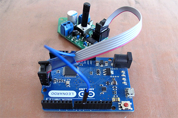
Here is a Leonardo board being used to program one of the dimmer boards:

With the new cable, it is easy to unplug the cable after programming to test out the system, then plug it back in with the right orientation (I used a shrouded header on the dimmer board) when reprogramming is needed.

Note that the reset line for the ISP cable connects to pin 10 of the programming Arduino board, which would be connected via a USB cable to the laptop that has the Arduino development environment on it.

I’ve seen several kluges on the web for connecting up Arduinos as ISPs, but none were as simple as and easy to use as what I did here, so I thought I ought to share it.


Filed under: Uncategorized Tagged: Arduino, Arduino as ISP, ATtiny, dimmable LED lamps, lamp

Self-Driving R/C Car Parks Itself Just Like a Lexus

Self-driving cars are in the news almost daily, but they are not exactly in my automotive budget for this decade. Today, that has changed. While this car might be smaller and not capable of giving me a ride, it’s still autonomous and, best of all, it is a project that I […]

Read more on MAKE

The post Self-Driving R/C Car Parks Itself Just Like a Lexus appeared first on Make: DIY Projects, How-Tos, Electronics, Crafts and Ideas for Makers.

Now Let’s See The World’s Largest Arduino

A few days ago we saw what would have been a killer Kickstarter a few years ago. It was the smallest conceivable ATtiny85 microcontroller board, with resistors, diodes, a USB connector, and eight pins for plugging into a breadboard. It’s a shame this design wasn’t around for the great Arduino Minification of Kickstarter in late 2011; it would have easily netted a few hundred thousand dollars, a TED talk, and a TechCrunch biopic.

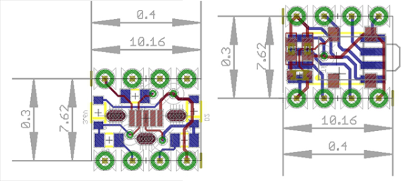
[AtomSoftTech] has thrown his gauntlet down and created an even smaller ‘tiny85 board. it measures 0.4in by 0.3in, including the passives, reset switch, and USB connector. To put that in perspective, the PDIP package of the ‘tiny85 measures 0.4 x 0.4. How is [Atom] getting away with this? Cheating, splitting the circuit onto two stacked boards, or knowing the right components, depending on how you look at it.

[Atom] is using a few interesting components in this build. The USB connector is a surface mount vertical part, making the USB cord stick out the top of this uC board. The reset button is extremely small as well, sticking out of the interior layer of the PCB sandwich.

[AtomSoft] has the project up on OSH Park ($1.55 for three. How cool is that?), and we assume he’ll be selling the official World’s Smallest Arduino-compatible board at Tindie in time.


Filed under: Arduino Hacks, ATtiny Hacks

What Is This, A Microcontroller Board For Ants?

You youngins probably don’t remember this, but a few years ago there was an arms race on Kickstarter to create the smallest Arduino-compatible microcontroller board. Since then, a few people have realized they can make more money on Kickstarter through fraud or potato salad, and the race to create the smallest ‘duino board petered out.

It’s a shame [Meizhu] wasn’t part of the great miniature Arduinofication of Kickstarter, because this project would have won. It’s an Atmel ATtiny85, with USB port, resistors, diodes, reset button, LED, and pin headers, that is just 72 mils larger than the PDIP package of the ‘tiny85. Outside of getting a bare die of ‘tiny85s, there isn’t much of a chance of this board becoming any smaller.

[Meizhu] was inspired to create this board from [Tim]‘s Nanite 85, which up until a few days ago was the current champion of micro microcontroller boards. With a bit of work in KiCAD, the new board layout was created that is just a hair larger than the 0.4″ x 0.4″ footprint of the PDIP ATtiny85. There were a few challenges in getting a working board this small; you’d be surprised how large the plastic bits around pin headers are, but with some very crafty soldering, [Meizhu] was able to get it to work.


Filed under: ATtiny Hacks

PWM controller

For the last couple of days I’ve been working on designing and building a PWM controller capable of handling moderately large currents at modest voltages (5A @ 9V). I don’t need high PWM frequency (4kHz should be plenty), but some of the loads I’m thinking of are rather nonlinear (very little current at low voltages, large but constant current at higher voltages).

I decided to try using an ATtiny chip as the PWM controller, because they are very cheap and can be programmed from the Arduino IDE (using an Arduino board as the ISP programmer).  I first prototyped the design using a Arduino ProMini (so I could add debugging statements and not have to worry about the 1kByte flash limitation of the ATtiny13A).  Once that was working, I rewrote the code for the ATtiny, doing some hand optimization to reduce the code size. I got it down to 880 bytes, but I can see why C is more popular than C++ for the really tiny processors—the C++ and Arduino overhead accounts for about 150 of the 1k bytes of flash!  I could make my code much smaller if I made it more special purpose and did everything in C rather than C++, but once it fit in the 1024 bytes, I stopped worrying about the size.

PWM controller using ATtiny 13A

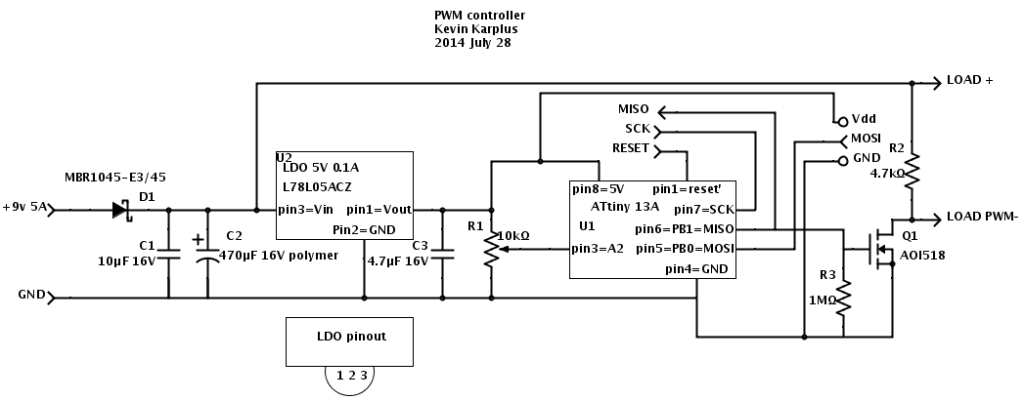
The design I came up with uses a low-dropout regulator to provide 5V for the ATtiny13A. A potentiometer provides analog input and a nFET provides a low-resistance switch for the output. I used the AOI518, because I have some on hand, but they are reaching the “end of life” so some other nFET may need to be used in a future design (perhaps one of the others in the series, such as the AOI516 which has a slightly lower on-resistance but a slightly higher gate capacitance).

The capacitors C1 and C2 are to keep the switching of the large load from propagating spikes into power supply.  The 470µF capacitor with a 5A current spike should limit the voltage slew to 10.6V/ms—with a 4.7kHz current square wave, this would be about a 1.1V triangle wave.  A polymer electrolytic is used (despite the price) to keep the effective series resistance small.  The one I’m using has an ESR of 9mΩ (@100kHz) and a ripple current up to 6.1A.  The leakage current could be as high as 1.5mA though.  C1 is a small ceramic capacitor to remove higher-frequency noise.  The big Schottky diode on the input is just to provide protection against accidentally hooking the circuit up backwards. I should probably add a 60¢ resettable fuse as well, to keep the current from getting excessive if there is a short.

When there is no load, the maximum current draw is 1.9mA for the pullup resistor R2, 0.9mA for the pot, 4–6mA for the ATtiny13A, and up to 1.5mA for C2, for a total of 8.3–10.3mA.  With a typically 80% efficient 9v switching power supply, this is a waste of about 100mW, or about 0.9kWh/year.

The pullup resistor R2 is not strictly necessary, but was added to keep the PWM pulses clean, turning all the way off even when the load had only tiny current draw—otherwise I could not get very low duty-cycle pulses to work well—the nFET acted as if it were a 1.3nF capacitor and kept a low voltage even when the nFET was off.  With the 4.7kΩ pullup, the voltage goes up appropriately, with a time constant of about 6µs.

So far, I’ve not tried the circuit with a large load—just with a small load that takes 13mA.  With that tiny a load, I don’t see any ripple in the power supply from the PWM.  With a 210mA load, the ripple on the power supply is noticeable: on top of the 20mV of ripple at about 20MHz with no load, I see 30mV of ripple synchronized with the switching of the PWM, when switching 210mA with a duty cycle of 1/2.  Without the 470µF polymer capacitor, the synchronized ripple is more like 200mV, indicating that the capacitor is indeed smoothing out the ripple.

The 30mV swing on 210mA implies that I should see about a 710mV swing if switching 5A.   That shouldn’t cause a problem in my design, but I do need to allow a little more voltage so that the swing isn’t a problem.  I could also use a bigger capacitor, but the polymer electrolytics are a bit expensive, and the regular wet electrolytics can’t handle a big ripple current—one with the same 6A ripple current rating would be 20 times the volume and 3 times the price of the polymer capacitor.

The high-frequency noise is almost certainly coming from the ATtiny, as it is synchronized with the PWM signal. The 5V power supply at the ATtiny is showing a 40mV ripple, which is large considering that there is a bypass capacitor on the Vdd pin.  There is a lot of inductance from the wiring on the board though, which could be increasing the propagation of the high-frequency noise.


Filed under: Uncategorized Tagged: Arduino, ATtiny, PWM

Custom Electronics and LED Panels Brighten Up a Nightclub

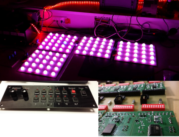
When [Robert] is presented with a challenge, he doesn’t back down. His friend dreamed of reusing some old LED panels by mounting them to the ceiling of the friend’s night club. Each panel consists of a grid of five by five red, green, and blue LEDs for a total of 75 LEDs per panel. It sounded like a relatively simple task but there were a few caveats. First, the controller box that came with the panels could only handle 16 panels and the friend wanted to control 24 of them. Second, the only input device for the controller was an infrared remote. The friend wanted an easy way for DJ’s to control the color of the panels and the infrared remote was not going to cut it. Oh yea, he also gave [Robert] just three weeks to make this happen.

[Robert] started out by building a circuit that could be duplicated to control each panel. The brain of this circuit is an ATtiny2313. For communication between panels, [Robert] chose to go with the DMX protocol. This was a good choice considering DMX is commonly used to control stage lighting effects. The SN75176 IC was chosen to handle this communication. In his haste to get this PCB manufactured [Robert] failed to realize that the LED panels were designed common cathode, as opposed to his 25 shiny new PCB’s which were designed to work with a common anode design. To remedy this, he switched out all of the n-channel MOSFET with p-channel MOSFET. He also spent a couple of hours manually cutting through traces and rewiring the board. After all of this, he discovered yet another problem. The LED’s were being powered from the same 5V source as the microcontroller. This lead to power supply issues resulting in the ATtiny constantly resetting. The solution was to add some capacitors.

Click past the break for more on [Robert's] LED panels.

As for software, [Robert] completely filled the ATtiny’s memory. He used three channels to control red, green, and blue. He added a fourth channel to control pre-designed animation effects such as fading, strobe, and random color. The DIP switches are normally used to set the address of the panel, but there is a second option to put the panel into standalone mode. In this mode, the switches are used to program the panel to perform specific effects with no DMX controller required.

Now that the panels were all designed and functioning, [Robert] still needed a way to control them. He used the laser cutter at Shackspace hackerspace to design the actual panel face and then mounted a bunch of buttons, switches, and potentiometers to it. All of those things were connected to a Teensy3 using perfboard and a hand wired circuit. Another SN75176 IC was used for the DMX communication from the control panel. The control panel allows the DJ to change between different pre-built animation effects, color effects, and also change the speed of the animations to match the speed of the music.


Filed under: led hacks
Hack a Day 31 May 12:00