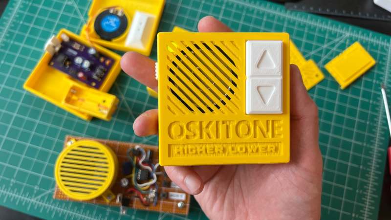
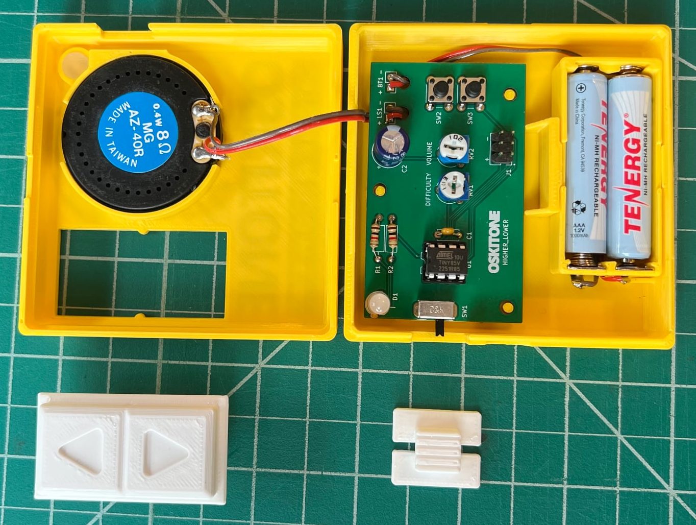
[Tommy] has a great write-up about designing and building a minimalistic handheld electronic game called “Higher Lower”. It’s an audio-driven game in which the unit plays two tones and asks the player to choose whether the second tone was higher in pitch, or lower. The game relies on 3D printed components and minimal electronics, limiting player input to two buttons and output to whatever a speaker stuck to an output pin from an ATtiny85 can generate.
Fastener-free enclosure means fewer parts, and on the inside are pots for volume and difficulty. We love the thoughtful little tabs that hold the rocker switch in place during assembly.
Gameplay may be straightforward, but working with so little raises a number of design challenges. How does one best communicate game state (and things like scoring) with audio tones only? What’s the optimal way to generate a random seed when the best source of meaningful, zero-extra-components entropy (timing of player input) happens after the game has already started? What’s the most efficient way to turn a clear glue stick into a bunch of identical little light pipes? [Tommy] goes into great detail for each of these, and more.
In addition to the hardware and enclosure design, [Tommy] has tried new things on the software end of things. He found that using tools intended to develop for the Arduboy DIY handheld console along with a hardware emulator made for a very tight feedback loop during development. Being able to work on the software side without actually needing the hardware and chip programmer at hand was also flexible and convenient.
We’ve seen [Tommy]’s work before about his synth kits, and as usual his observations and shared insights about bringing an idea from concept to kit-worthy product are absolutely worth a read.
You can find all the design files on the GitHub repository, but Higher Lower is also available as a reasonably-priced kit with great documentation suitable for anyone with an interest. Watch it in action in the video below.
Do you ever get tired of stressing your neck looking for planes in the sky? Worry not! Here is a neat and cheap Arduino/Ras Pi project to keep your neck sore free! [BANK ANGLE] presents a wonderfully simple plane tracking system using an affordable camera and basic microcontrollers.
The bulk of the system relies on a cheap rotating security camera that gets dissected to reveal its internals. Here stepper control wires can be found and connected to the control boards required to allow an Arduino nano to tell the motors when and where to spin. Of course, the camera system doesn’t just look everywhere until it finds a plane, a Raspberry Pi takes in data from local ADS-B data to know where a nearby plane is.
After that, all that’s left is a nifty overlay to make the professional look. Combining all these creates a surprisingly capable system that gives information on the aircraft’s azimuth, elevation, and distance.
If you want to try your hand at making your own version of [BLANK ANGLE]’s tracker, check out his GitHub page. Of course, tracking planes gets boring after a while so why not try tracking something higher with this open-source star tracker?
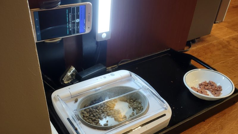
Cats are no respecters of personal property, as [Joe Mattioni] learned when one of his cats, [Layla] needed a special prescription diet. Kitty didn’t care for it, and since the other cat, [Foxy]’s bowl was right there– well, you see where this is going. To keep [Layla] out of [Foxy]’s food and on the vet-approved diet, [Joe] built an automatic feeding system with feline facial recognition. As you do.
The hardware consists of a heavily modified feed bowl with a motorized lid that was originally operated by motion-detection, an old Android phone running a customized TensorFlow Lite model, and hardware to bridge them together. Bowl hardware has yet to be documented on [Joe]’s project page, aside from the hint that an Arduino (what else?) was involved, but the write up on feline facial recognition is fascinating.
See, when [Joe] started the project, there were no cat-identifying models available– but there were lots of human facial recognition models. Since humans and cats both have faces, [Joe] decided to use the MobileFaceNet model as a starting point, and just add extra training data in the form of 5000 furry feline faces. That ran into the hurdle that you can’t train a TFLite model, which MobileFaceNet is, so [Joe] reconstructed it as a Keras model using Google CoLab. Only then could the training occur, after which the modified model was translated back to TFLite for deployment on the Android phone as part of a bowl-controller app he wrote.
No one, [Joe] included, would say that this is the easiest, fastest, or possibly even most reliable solution– a cat smart enough not to show their face might sneak in after the authorized feline has their fill, taking advantage of a safety that won’t close a bowl on a kitty’s head, for example–but that’s what undeniably makes this a hack. It sounds like [Joe] had a great learning adventure putting this together, and the fact that it kept kitty on the proper diet is really just bonus.
Want to go on a learning adventure of your own? Click this finely-crafted link for all the details about this ongoing contest.
First off, sometimes you just don’t need the speed. When you’re just blinking LEDs on a human timescale, the general-purpose Arduino functions are good enough. I’ve written loads of useful firmware that fits this description. When the timing requirements aren’t tight, slow as dirt can be fast enough.
But eventually you’ll want to build a project where the old slow-speed pin toggling just won’t cut it. Maybe it’s a large LED matrix, or maybe it’s a motor-control application where the loop time really matters. Or maybe it’s driving something like audio or video that just needs more bits per second. One way out is clever coding, maybe falling back to assembly language primitives, but I would claim that the right way is almost always to use the hardware peripherals that the chipmakers gave you.
For instance, in the end of the video linked above, the hacker wants to drive a large shift register string that’s lighting up an LED matrix. That’s exactly what SPI is for, and coming to this realization makes the project work with timing to spare, and in just a few lines of code. That is the way.
Which brings me to the double-edged sword that the Arduino’s abstraction creates. By abstracting away the chips’ hardware peripherals, it makes code more portable and certainly more accessible to beginners, who don’t want to learn about SPI and I2C and I2S and DMA just yet. But by hiding the inner workings of the chips in “user friendly” libraries, it blinds new users to the useful applications of these same hardware peripherals that clever chip-design engineers have poured their sweat and brains into making do just exactly what we need.
This isn’t really meant to be a rant against Arduino, though. Everyone has to start somewhere, and the abstractions are great for getting your feet wet. And because everything’s open source anyway, nothing stops you from digging deeper into the datasheet. You just have to know that you need to. And that’s why we write up videos like this every five years or so, to show the next crop of new hackers that there’s a lot to gain underneath the abstractions.
This article is part of the Hackaday.com newsletter, delivered every seven days for each of the last 200+ weeks. It also includes our favorite articles from the last seven days that you can see on the web version of the newsletter.
Want this type of article to hit your inbox every Friday morning? You should sign up!
Although plenty of us have our preferred language for coding, whether it’s C for its hardware access, Python for its usability, or Fortran for its mathematic prowess, not every language is specifically built for problem solving of a particular nature. Some are built as thought experiments or challenges, like Whitespace or Chicken but aren’t used for serious programming. There are a few languages that fit in the gray area between these regions, and one example of this is the language MOUSE which can now be run on an Arduino.
Although MOUSE was originally meant to be a minimalist language for computers of the late 70s and early 80s with limited memory (even for the era), its syntax looks more like a more modern esoteric language, and indeed it arguably would take a Python developer a bit of time to get used to it in a similar way. It’s stack-based, for a start, and also uses Reverse Polish notation for performing operations. The major difference though is that programs process single letters at a time, with each letter corresponding to a specific instruction. There have been some changes in the computing world since the 80s, though, so [Ivan]’s version of MOUSE includes a few changes that make it slightly different than the original language, but in the end he fits an interpreter, a line editor, graphics primitives, and peripheral drivers into just 2KB of SRAM and 32KB Flash so it can run on an ATmega328P.
There are some other features here as well, including support for PS/2 devices, video output, and the ability to save programs to the internal EEPROM. It’s an impressive setup for a language that doesn’t get much attention at all, but certainly one that threads the needle between usefulness and interesting in its own right. Of course if a language where “Hello world” is human-readable is not esoteric enough, there are others that may offer more of a challenge.
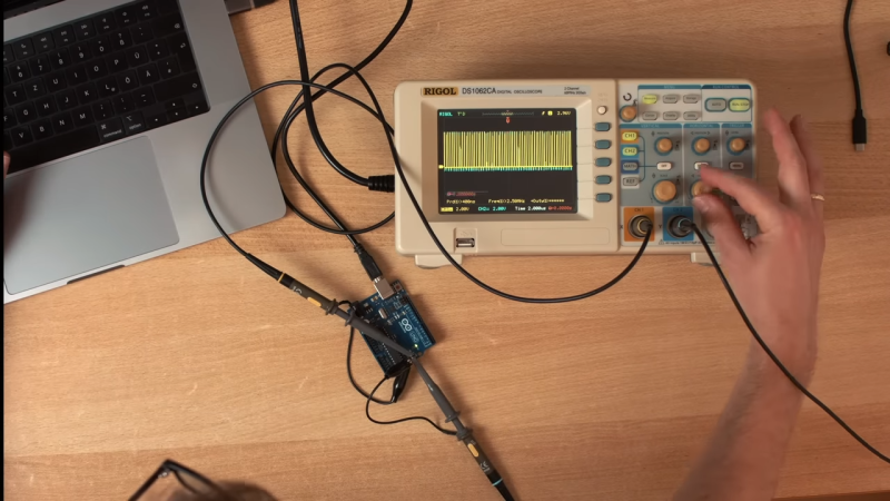
We love Arduino here at Hackaday; they’ve probably done more to make embedded programming accessible to more people than anything else in the history of the field. One thing the Arduino ecosystem is rarely praised for is its speed. That’s where [Playduino] comes in, with his video (embedded below) that promises to make everyone’s favourite microcontroller run 50x faster.
You might be expecting an unstable overclocking setup, with swapped crystals, tweaked voltages and a hefty heat sink, but no! This is stock hardware. The 50x speedup comes from one simple hack: don’t use digitalWrite();
If you aren’t familiar, the digitalWrite() function is one of the key functions Arduino gives you to operate its boards– specify the pin and the value (high or low) to drive it. It’s very easy, but it’s also very slow. [Playduino] takes a moment to show just how much is going on under the hood when you call digitalWrite(), and shows you what you can do instead if you have a need for speed. (Hint: there’s no Arduino-provided code involved; hardware registers and the __asm keyword show up.)
If you learned embedded programming in an earlier era, this will probably seem glaringly obvious. If you, like so many of us, got started inside of the Arduino ecosystem, these closer-to-the-metal programming techniques could prove useful tools in your quiver. Big thanks to [Stephan Walters] for the tip.
An ongoing refrain with modern movies is “Why is all of this CG?”– sometimes, it seems like practical effects are simultaneously a dying art, while at the same time modern technology lets them rise to new hights. [Davis Dewitt] proves that second statement with his RC movie star “robot” for an upcoming feature film.
The video takes us through the design process, including what it’s like to work with studio concept artists. As for the robot, it’s controlled by an Arduino Nano, lots of servos, and a COTS airplane R/C controller, all powered by li-po batteries. This is inside an artfully weathered and painted 3D printed body. Apparently weathering is important to make the character look like a well-loved ‘good guy’. (Shiny is evil, who knew?) Hats off to [Davis] for replicating that weathering for an identical ‘stunt double’.
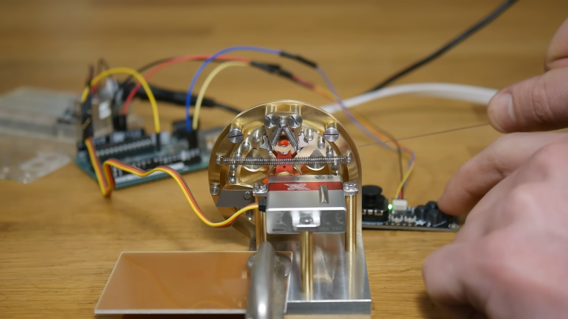
A common ratchet from your garage may work wonders for tightening hard to reach bolts on whatever everyday projects around the house. However, those over at [Chronova Engineering] had a particularly unusual project where a special ratchet mechanism needed to be developed. And developed it was, an absolutely beautiful machining job is done to create a ratcheting actuator for tendon pulling. Yes, this mechanical steampunk-esk ratchet is meant for yanking on the fleshy strings found in all of us.
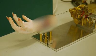
The unique mechanism is necessary because of the requirement for bidirectional actuation for bio-mechanics research. Tendons are meant to be pulled and released to measure the movement of the fingers or toes. This is then compared with the distance pulled from the actuator. Hopefully, this method of actuation measurement may help doctors and surgeons treat people with impairments, though in this particular case the “patient” is a chicken’s foot.
Blurred for viewing ease
Manufacturing the mechanism itself consisted of a multitude of watch lathe operations and pantographed patterns. A mixture of custom and commercial screws are used in combination with a peg gear, cams, and a high performance servo to complete the complex ratchet. With simple control from an Arduino, the system completes its use case very effectively.
In all the actuator is an incredible piece of machining ability with one of the least expected use cases. The original public listed video chose to not show the chicken foot itself due to fear of the YouTube overlords.
If you wish to see the actuator in proper action check out the uncensored and unlisted video here.
Thanks to [DjBiohazard] on our Discord server tips-line!
You can send data from one Arduino to another, or create a wireless remote-control system using inexpensive long-range 315MHz or 433MHz wireless data units.
Using this tutorial so you can quickly test and use your units, giving you the knowledge to build upon and make your own projects. So let’s get started!
Testing the modules
Our first guide is to simply test that data can be sent and received from one module to another. This is also an ideal setup for testing the radio range of the units in your area.
An external power supply for one Arduino. This can be an AC-DC wall wart, USB power bank, anything to power it without using the PC that has the receiving Arduino connected to it.
You also need to install the VirtualWire Arduino library. To do this:
Download this .zip file into a temporary or your download directory.
Open the Arduino IDE and select Sketch > Include Library > Add .zip Library…
Navigate to the library .zip download and click “Open”:
After a few moments the library will be installed. You can check that this has completed by selecting Sketch > Include Library> then scroll down the long pop-up menu until you see “VirtualWire” as shown below:
Now – back to the hardware. Allocate one Arduino to be the transmitter, and one the receiver. Upload the following sketch to the transmitter board:
This file contains hidden or bidirectional Unicode text that may be interpreted or compiled differently than what appears below. To review, open the file in an editor that reveals hidden Unicode characters.
Learn more about bidirectional Unicode characters
… and upload the following sketch to the receiver board:
This file contains hidden or bidirectional Unicode text that may be interpreted or compiled differently than what appears below. To review, open the file in an editor that reveals hidden Unicode characters.
Learn more about bidirectional Unicode characters
Wiring the modules is very easy, they are labelled well and drop straight into a solderless breadboard:
Now connect the transmitter module to your transmitter Arduino as such:
Arduino GND to transmitter GND
Arduino 5V to transmitter Vcc
Arduino digital pin 12 to transmitter SIG:
Next, connect the receiver module to your transmitter Arduino as such:
Arduino GND to receiver GND
Arduino 5V to receiver Vcc
Arduino digital pin 11 to receiver SIG
LED and resistor in series between Arduino digital pin 2 and GND
Now that you’ve assembled both circuits, and uploaded the transmitter and receiver sketches to each board – it’s time to test.
Connect the transmitter board to power, and connect the receiver board to the PC. If not already open, run the Arduino IDE and open the serial monitor. You should notice two things:
The LED on your receiver circuit should blink around once per second. When the LED blinks, this indicates the receiver circuit has successfully received a complete message from the transmitter
The data sent from the transmitter is displayed in the serial monitor.
You can see this in action through the following video:
Our camera had trouble capturing the LED blink in some moments, but that’s ok.
You can also use this two Arduino setup to test the radio range – simply power the transmitter, and power the receiver circuit with a portable source of energy, such as a USB power bank – then walk away from the transmitter. The LED will stop blinking when you’re out of radio range.
You can increase the radio range by increasing the voltage to the transmitter unit – up to 12V DC.
Wireless Remote Control
Now to do something useful – create a wireless digital output control. Our transmitter will have two buttons, and our receiver will control two LEDs via digital outputs. Naturally this is an example, you can use this as a base to control other devices if required.
An external power supply for one Arduino. This can be an AC-DC wall wart, USB power bank, anything to power it without using the PC that has the receiving Arduino connected to it.
We will use two tactile buttons and 10k Ohm pull-down resistors for input. If you’re not familiar with digital inputs and buttons, the building block for this is shown below.
The example diagram uses D12 as the input pin, however for this project your transmitter circuit will need two button circuits, using D8 and D7:
To save time we will use button breakout boards which combine the circuit into a neat unit ideal for prototyping:
Your receiver circuit is the same as the test circuit at the start of this tutorial, except that anothe LED circuit is added to digital pin 3.
Now for the sketches. Upload the following sketch to the transmitter (buttons) Arduino…
This file contains hidden or bidirectional Unicode text that may be interpreted or compiled differently than what appears below. To review, open the file in an editor that reveals hidden Unicode characters.
Learn more about bidirectional Unicode characters
… and upload the following sketch to the receiver (LEDs) Arduino:
This file contains hidden or bidirectional Unicode text that may be interpreted or compiled differently than what appears below. To review, open the file in an editor that reveals hidden Unicode characters.
Learn more about bidirectional Unicode characters
You can see a quick demonstration in the following video:
So how did that work?
Review the transmitter sketch. A character is sent over the wireless link which determines the latest operation of the buttons – a, b, c or d (button one high/low, button two high/low).
Review the receiver sketch – on line 19 the switch-case function interrogates the incoming character from the wireless link and determines the action – in this case, controlling the digital outputs which have the two LEDs.
The response speed may seem a little slow – this will be affected by the data speed (300 bps). You can experiment with data speed and radio range (and voltage to the transmitter unit)
You can then alter this for your own means. You may not want to continuously send data as our example does, depending on your needs. As always, have fun and experiment.
Sending data wirelessly from one Arduino to another
Now we’ll show how to send some data in the form of an integer over our wireless link. This is ideal for sending the values of analog inputs, or other data that can be represented as an integer.
The hardware is the same as before – one Arduino transmitting and one Arduino receiving – with the receiver unit connected to a PC so we can use the Serial Monitor to display the received data.
Upload the following sketch to the transmitter Arduino…
This file contains hidden or bidirectional Unicode text that may be interpreted or compiled differently than what appears below. To review, open the file in an editor that reveals hidden Unicode characters.
Learn more about bidirectional Unicode characters
… and the following sketch to the receiver Arduino.
This file contains hidden or bidirectional Unicode text that may be interpreted or compiled differently than what appears below. To review, open the file in an editor that reveals hidden Unicode characters.
Learn more about bidirectional Unicode characters
Once operating and in radio range, the onboard LEDs will indicate successful transmission and reception of data. Open the serial monitor, and after a moment you will be presented with the data from analogue pin 1 of the transmitter Arduino – for example:
So how did that work?
Review the trasmitter sketch. We took a value from analog pin 1, and stored it into an integer variable on line 25. The VirtualWire library is geared to send data as characters so we convert the integer to a character array on line 28 – which is then sent as usual as shown in line 31.
Now review the receiver sketch. Nothing unusual, and the data from the receiver (in character form) is fed into the array at line 35. Once completed, we add “\0” to the end of the array to signify the end of the data.
The array is then converted back to an integer on line 42, then sent to the Serial Monitor.
So there you have it, we’ve sent integers across the airwaves. You can use your own “codes” with integers to mean all sorts of things and send them across. Ideal for temperature sensors, or anything really.
I hope you had fun experimenting with wireless units, or at least enjoyed reading about the possibilities. To keep up to date with new posts at tronixstuff.com, please subscribe to the mailing list in the box on the right, or follow us on x – @tronixstuff.
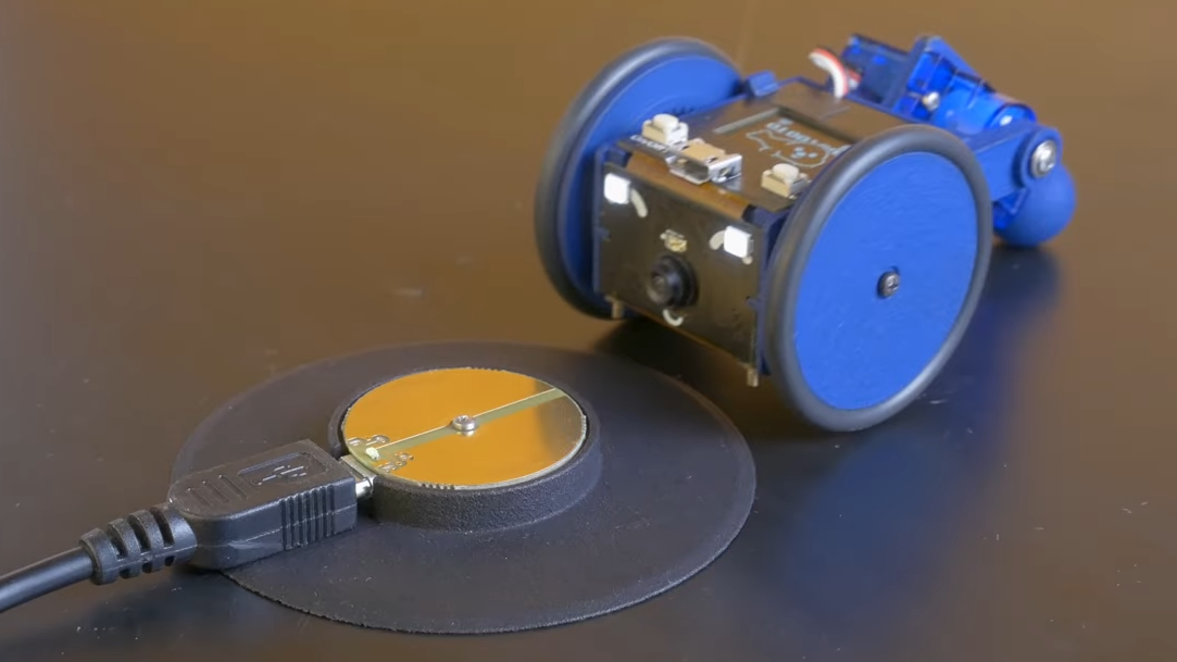
[Charmed Labs] are responsible for bringing numerous open-source hardware products to fruition over the years, and their latest device is an adorably small robotic camera platform called Goby, currently crowdfunding for its initial release. Goby has a few really clever design features and delivers a capable (and hackable) platform for under 100 USD.
Goby embraces its small size, delivering what its creators dub “tinypresence” — or the feeling of being there, but on a very small scale. Cardboard courses, LEGO arenas, or even tabletop gaming scenery hits different when experienced from a first-person perspective. Goby is entirely reprogrammable with nothing more than a USB cable and the Arduino IDE, while costing less than most Arduino starter kits.
Recharging happens by driving over the charger, then pivoting down so the connectors (the little blunt vampire fangs under and to each side of the camera) come into contact with the charger.
One of the physical features we really like is the tail-like articulated caster at the rear. Flexing this pivots Goby up or down (and can even flip Goby completely over), allowing one to pan and tilt the view without needing to mount the camera on a gimbal. It also comes into play for recharging; Goby simply moves over the disc-shaped charger and pivots down to make contact.
At Goby‘s heart is an ESP32-S3 and OmniVision OV2640 camera sensor streaming a live video feed (and driving controls) with WebRTC. Fitting the WebRTC stack onto an ESP32 wasn’t easy, but opens up possibilities beyond just media streaming.
Goby is set up to make launching an encrypted connection as easy as sharing a URL or scanning a QR code. The link is negotiated between bot and client with the initial help of an external server, and once a peer-to-peer connection is established, the server’s job is done and it is out of the picture. [Charmed Labs]’s code for this functionality — named BitBang — is in beta and destined for an open release as well. While BitBang is being used here to make it effortless to access Goby remotely, it’s more broadly intended to make web access for any ESP32-based device easier to implement.
As far as tiny remote camera platforms go, it might not be as small as rebuilding a Hot Wheels car into a micro RC platform, but it’s definitely more accessible and probably cheaper, to boot. Check it out at the Kickstarter (see the first link in this post) and watch it in action in the video, embedded just below the page break.