Posts with «arduino» label

Arduino Boombox

Add sound or music to your project using the "Grove Serial MP3 Player".

An Arduino UNO will be used to control the Grove Serial MP3 player by sending it specific serial commands. The Grove Base Shield allows for the easy connection of Grove sensor modules to an Arduino UNO without the need for a breadboard. A sliding potentiometer, switch and button will be connected to the Base shield along with the Serial MP3 player. A specific function will be assigned to each of the connected sensor modules to provide a useful interface:

  • Sliding Potentiometer – Volume control
  • Button – Next Song
  • Switch – On/Off (toggle)
Once the MP3 module is working the way we want, we can then build a simple enclosure for it. Grab a shoe-box, print out your favourite design, and make your very own Arduino BOOMBOX!


Video

Watch the following video to see the project in action


Parts Required:

Optional components (for the BoomBox Enclosure):
  • Empty Shoe Box
  • Paper
  • Printer
  • Glue
If I had a 3D printer - I would have printed my own enclosure, but a shoebox seems to work just fine.


Putting it Together

Place the Grove Base shield onto the Arduino UNO,
and then connect each of the Grove Modules as per the table below.


If you do not have a Grove Base shield,
you can still connect the modules directly to the Arduino as per the table below:


When you are finished connecting the modules, it should look something like this:
  (ignore the battery pack):
 

As you can see from the picture above. You can cut holes out of the shoebox and stick the modules in place. Please ignore the battery pack, because you won't use it until after you have uploaded the Arduino code.


Arduino Sketch


  1
2
3
4
5
6
7
8
9
10
11
12
13
14
15
16
17
18
19
20
21
22
23
24
25
26
27
28
29
30
31
32
33
34
35
36
37
38
39
40
41
42
43
44
45
46
47
48
49
50
51
52
53
54
55
56
57
58
59
60
61
62
63
64
65
66
67
68
69
70
71
72
73
74
75
76
77
78
79
80
81
82
83
84
85
86
87
88
89
90
91
92
93
94
95
96
97
98
99
100
101
102
103
104
105
106
107
108
109
110
111
112
113
114
115
116
117
118
119
120
121
122
123
124
125
126
127
128
129
130
131
132
133
134
135
136
137
138
139
140
141
142
143
144
145
146
147
148
149
150
151
152
153
154
155
156
157
158
159
160
161
162
163
164
165
166
167
168
169
170
171
172
173
174
175
176
177
178
179
180
181
182
183
184
185
186
187
188
189
190
191
192
193


/* ===============================================================================
      Project: Grove Serial MP3 Player overview
       Author: Scott C
      Created: 9th March 2015
  Arduino IDE: 1.6.0
      Website: http://arduinobasics.blogspot.com/p/arduino-basics-projects-page.html

  Description: The following Arduino sketch will allow you to control a Grove Serial MP3 player
               with a Grove Sliding Potentiometer (volume), a Grove button (next song), 
               and a Grove Switch (on/off). It will also show you how to retrieve some useful information from the player. 
               Some functions are not used in this sketch,but have been included for your benefit. 
               
               Additional features and functionality can be found on the WT5001 voice chip datasheet 
               which I retrieved from here: http://goo.gl/ai6oQ9
               
               The Seeedstudio wiki was a very useful resource for getting started with the various Grove modules:
               http://goo.gl/xOiSCl
=============================================================================== */

#include <SoftwareSerial.h>
SoftwareSerial mp3(2, 3); // The Grove MP3 Player is connected to Arduino digital Pin 2 and 3 (Serial communication)
int potPin = A0; // The Sliding Potentiometer is connected to AnalogPin 0
int potVal = 0; // This is used to hold the value of the Sliding Potentiometer
byte mp3Vol = 0; // mp3Vol is used to calculate the Current volume of the Grove MP3 player
byte oldVol = 0; // oldVol is used to remember the previous volume level
int ledPin = A1; // The Grove sliding potentiometer has an onboard LED attached to Analog pin 1.

int switchPin = 12; // The Grove Switch(P) is connected to digital Pin 12
int switchStatus = 0; // This is used to hold the status of the switch
int switchChangeStatus = 0; // Used to identify when the switch status has changed

int buttonPin = 5; // The Grove Button is connected to digital pin 5
int buttonStatus = 0; // This is used to hold the status of the button


void setup(){
  //Initialise the Grove MP3 Module
  delay(2500);
  mp3.begin(9600);
  
        
  // initialize the pushbutton and switch pin as an input:
  pinMode(buttonPin, INPUT);
  pinMode(switchPin, INPUT);
  
  // set ledPin on the sliding potentiometer to OUTPUT
  pinMode(ledPin, OUTPUT);
  
  //You can view the following demostration output in the Serial Monitor
  demonstrate_GET_FUNCTIONS();     
}


void loop(){
  switchStatus = digitalRead(switchPin);
  if(switchStatus==HIGH){
    if(switchChangeStatus==LOW){ // When Arduino detects a change in the switchStatus (from LOW to HIGH) - play song
      setPlayMode(0x02);                     // Automatically cycle to the next song when the current song ends
      playSong(00,01);                       // Play the 1st song when you switch it on
      switchChangeStatus=HIGH;
    }
    
    potVal = analogRead(potPin); // Analog read values from the sliding potentiometer range from 0 to 1023
    analogWrite(ledPin, potVal/4); // Analog write values range from 0 to 255, and will turn LED ON once potentiometer reaches about half way (or more).
    mp3Vol = map(potVal, 0, 1023, 0,31); // Convert the potentometer reading (0 - 1023) to fit within the MP3 player's Volume range (0 - 31)
    if((mp3Vol>(oldVol+1))|(mp3Vol<(oldVol-1))){ // Only make a change to the Volume on the Grove MP3 player when the potentiometer value changes
      oldVol = mp3Vol;
      setVolume(mp3Vol);
      delay(10); // This delay is necessary with Serial communication to MP3 player
    }

    buttonStatus = digitalRead(buttonPin);
    if(buttonStatus==HIGH){ // When a button press is detected - play the next song
      playNextSong();
      delay(200); // This delay aims to prevent a "skipped" song due to slow button presses - can modify to suit.
    }
  } else {
    if(switchChangeStatus==HIGH){ // When switchStatus changes from HIGH to LOW - stop Song.
      stopSong();
      switchChangeStatus=LOW;
    }
  } 
}


// demonstrate_GET_FUNCTIONS  will show you how to retrieve some useful information from the Grove MP3 Player (using the Serial Monitor).
void demonstrate_GET_FUNCTIONS(){
        Serial.begin(9600);
        Serial.print("Volume: ");
        Serial.println(getVolume());
        Serial.print("Playing State: ");
        Serial.println(getPlayingState());
        Serial.print("# of Files in SD Card:");
        Serial.println(getNumberOfFiles());
        Serial.println("------------------------------");
}


// writeToMP3: is a generic function that aims to simplify all of the methods that control the Grove MP3 Player

void writeToMP3(byte MsgLEN, byte A, byte B, byte C, byte D, byte E, byte F){
  byte codeMsg[] = {MsgLEN, A,B,C,D,E,F};
  mp3.write(0x7E); //Start Code for every command = 0x7E
  for(byte i = 0; i<MsgLEN+1; i++){
    mp3.write(codeMsg[i]); //Send the rest of the command to the GROVE MP3 player
  }
}


/* The Following functions control the Grove MP3 Player : see datasheet for additional functions--------------------------------------------*/

void setPlayMode(byte playMode){
  /* playMode options:
        0x00 = Single song - played only once ie. not repeated.  (default)
        0x01 = Single song - cycled ie. repeats over and over.
        0x02 = All songs - cycled 
        0x03 = play songs randomly                                           */
        
  writeToMP3(0x03, 0xA9, playMode, 0x7E, 0x00, 0x00, 0x00);  
}


void playSong(byte songHbyte, byte songLbyte){ // Plays the selected song
  writeToMP3(0x04, 0xA0, songHbyte, songLbyte, 0x7E, 0x00, 0x00);            
}


void pauseSong(){ // Pauses the current song
  writeToMP3(0x02, 0xA3, 0x7E, 0x00, 0x00, 0x00, 0x00);
}


void stopSong(){ // Stops the current song
  writeToMP3(0x02, 0xA4, 0x7E, 0x00, 0x00, 0x00, 0x00);
}


void playNextSong(){ // Play the next song
  writeToMP3(0x02, 0xA5, 0x7E, 0x00, 0x00, 0x00, 0x00);
}


void playPreviousSong(){ // Play the previous song
  writeToMP3(0x02, 0xA6, 0x7E, 0x00, 0x00, 0x00, 0x00);
}


void addSongToPlayList(byte songHbyte, byte songLbyte){
  //Repeat this function for every song you wish to stack onto the playlist (max = 10 songs)
  writeToMP3(0x04, 0xA8, songHbyte, songLbyte, 0x7E, 0x00, 0x00);
}


void setVolume(byte Volume){ // Set the volume
  byte tempVol = constrain(Volume, 0, 31);
  //Volume range = 00 (muted) to 31 (max volume)
  writeToMP3(0x03, 0xA7, tempVol, 0x7E, 0x00, 0x00, 0x00); 
}


/* The following functions retrieve information from the Grove MP3 player : see data sheet for additional functions--------------*/

// getData: is a generic function to simplifly the other functions for retieving information from the Grove Serial MP3 player
byte getData(byte queryVal, int dataPosition){
  byte returnVal = 0x00;
  writeToMP3(0x02, queryVal, 0x7E, 0x00, 0x00, 0x00, 0x00);
  delay(50);
  for(int x = 0; x<dataPosition; x++){
    if(mp3.available()){
      returnVal = mp3.read();
      delay(50);
    }
  }
  return(returnVal);
}

byte getVolume(){ //Get the volume of the Grove Serial MP3 player
  //returns value from 0 - 31
  return(getData(0xC1, 4));
}

byte getPlayingState(){ //Get the playing state : Play / Stopped / Paused
  //returns 1: Play, 2: Stop, 3:Paused
  return(getData(0xC2, 2));
}


byte getNumberOfFiles(){ //Find out how many songs are on the SD card
  //returns the number of MP3 files on SD card
  return(getData(0xC4, 3));
}

You will notice from the code, that I did not utilise every function. I decided to include them for your benifit. This Serial MP3 module makes use of a high quality MP3 audio chip known as the "WT5001". Therefore, you should be able to get some additional features and functionality from this document. Plus you may find some extra useful info from the Seeedstudio wiki.
 
IMPORTANT: You need to load your MP3 sounds or songs onto the SDHC card before you install it onto the Serial MP3 player.
 
Once the SDHC card is installed, and your code is uploaded to the Arduino, all you have to do now is connect the MP3 player to some headphones or a powered speaker. You can then power the Arduino and modules with a battery pack or some other portable power supply.
 
You can design and decorate the shoebox in any way you like. Just print out your picture, glue them on, and before you know it, you will have your very own Arduino Boombox.


Comments

I was very surprised by the quality of the sound that came from the MP3 module. It is actually quite good.

This tutorial was an introduction to the Grove Serial MP3 module in it's most basic form. You could just as easily use some other sensor to trigger the MP3 module. For example, you could get it to play an alert if a water leak was detected, or if a door was opened, or if the temperature got too high or too low. You could get it to play a reminder when you walk into your room. The possibilities are endless.

I really liked this module, and I am sure it will appear in a future tutorial.


If you like this page, please do me a favour and show your appreciation :

 
Visit my ArduinoBasics Google + page.
Follow me on Twitter by looking for ScottC @ArduinoBasics.
I can also be found on Pinterest and Instagram.
Have a look at my videos on my YouTube channel.


However, if you do not have a google profile...
Feel free to share this page with your friends in any way you see fit.

Bruce Sterling interviews Massimo Banzi on Casa Jasmina and more!

During the first opening of Casa Jasmina, Bruce Sterling found a moment to discuss about IoT, Casa Jasmina and Arduino future plans with Massimo Banzi. Check out this exclusive video were two of the minds behind the Casa Jasmina project dialogate about the future:


Solar Charge Controller Improves Efficiency of Solar Panels

The simplest and easiest way to charge a battery with a solar panel is to connect the panel directly to the battery. Assuming the panel has a diode to prevent energy from flowing through it from the battery when there’s no sunlight. This is fairly common but not very efficient. [Debasish Dutta] has built a charge controller that addresses the inefficiencies of such a system though, and was able to implement maximum power point tracking using an Arduino.

Maximum power point tracking (MPPT) is a method that uses PWM and a special DC-DC converter to match the impedance of the solar panel to the battery. This means that more energy can be harvested from the panel than would otherwise be available. The circuit is placed in between the panel and the battery and regulates the output voltage of the panel so it matches the voltage on the battery more closely. [Debasish] reports that an efficiency gain of 30-40% can be made with this particular design.

This device has a few bells and whistles as well, including the ability to log data over WiFi, an LCD display to report the status of the panel, battery, and controller, and can charge USB devices. This would be a great addition to any solar installation, especially if you’ve built one into your truck.

This is [Debasish]’s second entry to The Hackaday Prize. We covered his first one a few days ago. That means only one thing: start a project and start documenting it on hackaday.io


Filed under: solar hacks, The Hackaday Prize

Getting Started with Intel Edison Mini Breakout Board

Let’s start exploring a bit more about Intel Edison. As you may already know, Intel provides 2 different hardware platforms to work with Edison development board: the core module is called Intel Edison Compute Module, while the 2 extension boards are called Intel Edison Arduino Board and Intel Edison Breakout Board respectively. We refer to them as the Arduino module and mini-breakout board, respectively. The tutorial of this week is called Getting Started with Intel Edison Mini Breakout Board:

It is probably more common to use the Arduino module, since it’s easy to use and has many useful features, most notably the pin headers. However, the mini-breakout’s main advantage comes from its size and possible use as a wearable.

In this tutorial, you’ll get more familiar the mini-breakout board, learn how to use it for basic tasks, and then build a small “blink” example based on this knowledge.

Follow the link and explore

Open-Source Robotic Arm Now Within Reach

For anyone looking for a capable robotic arm for automation of an industrial process, education, or just a giant helping hand for a really big soldering project, most options available can easily break the bank. [Mads Hobye] and the rest of the folks at FabLab RUC have tackled this problem, and have come up with a very capable, inexpensive, and open-source industrial arm robot that can easily be made by anyone.

The robot itself is Arduino-based and has the option to attach any end effector that might be needed for a wide range of processes. The schematics for all of the parts are available on the project site along with all of the Arduino source code. [Mads Hobye] notes that they made this robot during a three-day sprint, so it shouldn’t take very long to get your own up and running. There’s even a virtual robot that can be downloaded and used with the regular robot code, which can be used for testing or for simply getting the feel for the robot without having to build it.

This is a great project, and since it’s open source it will be great for students, small businesses, and hobbyists alike. The option to attach any end effector is also a perk, and we might suggest trying out [Yale]’s tendon-driven robotic hand. Check after the break for a video of this awesome robot in action.


Filed under: robots hacks

Rocket Controls Fit for a Kerbal

Kerbal Space Program is a space simulation game. You design spacecraft for a fictional race called Kerbals, then blast those brave Kerbals into space. Sometimes they don’t make it home.

If controlling spacecraft with your WASD keys isn’t immersive enough for you, [marzubus] has created a fully featured KSP control console. It sports a joystick, multiple displays, and an array of buttons and switches for all your flight control needs. The console was built using a modular approach, so different controls can be swapped in and out as needed.

Under the hood, three Arduinos provide the interface between the game and the controls. One Arduino Mega runs HoodLoader2 to provide joystick data over HID. A second Mega uses KSPSerialIO to communicate with the game over a standard COM port interface. Finally, a Due interfaces with the displays, which provide information on the current status of your spacecraft.

All of the parts are housed in an off the shelf enclosure, which has a certain Apollo Mission Control feel to it. All [marzubus] needs now is a white vest with a Kerbal badge on it.


Filed under: Arduino Hacks

Arduino v Arduino: Part II

Since our last article covering the Arduino v. Arduino case, we’ve received a couple of tips, done some more digging, and learned a lot more about what’s going on. We thought it was time to share the story with you as it develops.

The Players

In short, there are two companies calling themselves “Arduino” at the moment. One, Arduino LLC was founded by [Massimo Banzi], [David Cuartielles], [David Mellis], [Tom Igoe] and [Gianluca Martino] in 2009, runs the website arduino.cc, and has been directing and releasing the code that makes it all work. Most of these folks had been working together on what would become the Arduino project since as early as 2005.

The other “Arduino” used to be called Smart Projects and was the manufacturing arm of the project founded and run by [Gianluca Martino]. Smart Projects changed their name to Arduino SRL in November 2014. (A “Società a responsabilità limitata” is one form of Italian limited-liability company.) They have been a major producer of Arduino boards from the very beginning and recently registered the domain arduino.org.

Around the time of the name change [Martino] sold his shares to a Swiss firm Gheo SA and [Federico Musto] was appointed CEO. Gheo SA is owned and directed by [Musto], who also runs a design consultancy based in the US and Taiwan called dog hunter, LLC.

dog hunter and [Musto] helped develop the Arduino Yun, a mashup of an Arduino with an OpenWRT-compatible WiFi router. dog hunter also runs the Linino.org website to support the Linux distribution that’s running on the router part of the Yun.

In short, on one side is Arduino LLC, run by the original Arduino Five and hosting arduino.cc. On the other is now called Arduino SRL, run by a former co-developer [Federico Musto] who bought out the largest producer of Arduino boards and opened up arduino.org.

The Legal Situation

When we previously reported that Arduino LLC brought a lawsuit against Arduino SRL, we only had half of the story. This suit, filed in January 2015 and still pending, is predated by an earlier trademark action filed by Arduino SRL against Arduino LLC.

The trademark case is a petition to cancel Arduino LLC’s trademark on Arduino, filed by Smart Projects SRL on October 3, 2014. This case is also still pending, and because it’s in front of the USPTO, it’s entirely visible. Here’s what we know.

The claims to invalidate Arduino LLC’s trademark on “Arduino” (PDF) can basically be summarized as follows: “We filed for trademark in September of 2014 and have been producing boards labelled Arduino since 2005. Arduino LLC only came into being in 2009 and wasn’t in control of the name at the time it applied for the trademark.”

To which Arduino LLC’s response (PDF) essentially reads “We’ve had the trademark on the word Arduino longer than you have, and we deny all the rest.”

The timeline for the case is laid out here (PDF). Basically, the discovery phase lasts until June 2015, and there’s not going to be a decision until after Christmas unless they settle early.

We’re not lawyers, but it looks like the case is going to revolve around whether or not Arduino LLC actually controlled the “Arduino” name at the time it trademarked it, and whether the extensive production of boards labelled “Arduino” by Smart Projects invalidates that trademark. The relevant trademark law can be found here and if you know your stuff on this, please feel free to illuminate us in the comments or with a direct e-mail to us directly or through the tip line.

So to recap the story so far, two websites, two “Arduinos”, and two lawsuits.

A Tale of Two Internets of Things

Not surprisingly, both groups have differing versions of where to go from here, but both sides are betting on the Internet of Things. Arduino LLC has partnered with Intel on the Galileo and more recently is working with BeagleBoard.org on the forthcoming Arduino TRE. Arduino SRL is sticking with the WiFi router MIPS solution that powers the Yun and keeping it in-house.

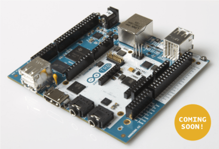
As previously mentioned, the Yun was at least co-designed with [Musto] and dog hunter. And now on arduino.org, there’s a placeholder product photo for the “Arduino Yun Mini” with the date April 30, 2015 attached. The Yun Mini looks exactly like the Linino One in a different color scheme, and it doesn’t take much of a hardware detective to put two and two together, given that [Musto] is now CEO of both dog hunter (which runs Linino.org) and Arduino SRL. The Yun Mini is, naturally, conspicuously lacking from the arduino.cc product lineup.


The next step up from the Yun on the arduino.cc site is the Arduino TRE, which is also a Linux-based solution coupled with an ATmega32u4. In this case, however, the Linux computer comes in the form of a 1-GHz Sitara AM335x processor, essentially a Beaglebone/Arduino mashup. And one can’t help but notice the tagline on the TRE page: “Arduino TRE, the first Arduino board manufactured in the U.S.” which is a dramatic shift away from the proudly “Made in Italy” silkscreens that adorn the Smart Projects / Arduino SRL boards.

Is this the reason for the schism? Massimo Banzi has said that he’s interested in working with many other producers to get newer and better Arduino products out there and would even like to be able to sell in China, land of the clones. (translate)  [Martino] and now [Musto] clearly have a vested interest in keeping production in Italy, while Arduino LLC’s interests are better served by going global. Perhaps it’s only natural that the two part ways.

The Code

Finally, the story takes a slightly cheeky turn in the most recent version of the Arduino IDE, released on March 10. As of version 1.6.1, there’s been a patch to the Arduino codebase that pops up a warning dialog when an “Arduino” with the USB Vendor ID (VID) 0x2A03 is flashed. The pop-up message reads “This board comes from an uncertified manufacturer. We won’t be able to provide any support if it doesn’t work as expected.”

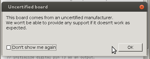
You may not be surprised that USB VID 0x2A03 belongs to “dog hunter AG”.  The Arduino IDE pops up the “uncertified manufacturer” warning any time that this VID is used, on any board type. Conspicuously missing in all of this are any of the VIDs in use by the various other counterfeit “Arduino” boards running around out there. Either there are too many of them to address directly, or this is a targeted, tactical strike against the Arduino SRL camp.

If you don’t have a board with VID 0x2A03, you can see the changes to the IDE on GitHub for the commit “Added warning for uncertified boards“.  Scroll on down to the changes to the file “hardware/arduino/avr/boards.txt” and you’ll see what’s going on. (And smile if you don’t have to code in Java for a living: nearly 600 lines of code added just to implement a simple pop-up dialog!)

Apparently, at least a couple of people with an UNO and a Mega256 have seen the warning and claim to have bought their devices through reputable retailers, including Mouser.

Now this isn’t an FTDI-style bricking; it’s just a pop-up dialog. What’s even nicer is that it comes with a “Don’t show me again” button so that you’re not constantly nagged. And it does recognize the boards so that they function normally, but it’s definitely a scare for users when they first stumble upon it.

The Future

So what does all of this mean for the future of Arduino as we know it? There’s certainly been a code fork and there are at least two divergent hardware design approaches to the IoT and strategic visions for the two firms. The trademark issues may not be resolved until 2016, though, so in the mean time there’s going to be significant market confusion. Not to mention the two similar websites.

You can certainly bet that both companies will be pushing themselves to get good product to market and trying to keep hold on the community. Maybe that will all be good for us in the end? Post your wild guesses and conspiracy theories in the comments.

We’ll keep you posted when we learn even more.  If you’ve got leads that you’d like us to chase down, hit us up on the tip line.

And thanks very much to [Concerned User] for the tipoff to the trademark filing and to [Another Anonymous Tipster] for the tip to the IDE version 1.6.1 changes.


Filed under: Arduino Hacks, news, slider
Hack a Day 12 Mar 12:00

Control Anything with an Apple Remote

If you’re like us, you probably have more than one Apple Remote kicking around in a parts drawer, and if you’re even more like us, you’re probably really annoyed at Apple’s tendency to use proprietary hardware and software at every turn (lightning connector, anyone?). But there’s hope for the Apple Remote now: [Sourcery] has completed a project that allows an Apple Remote to control anything you wish.

The idea is fairly straightforward: A device interprets the IR signals from an Apple Remote, and then outputs another IR signal that can do something useful on a non-Apple product. [Sourcery] uses an Arduino to do the IR translation, along with a set of IR emitters and detectors, and now the Apple Remote can control anything, from stereos to TVs to anything you can imagine. It also doesn’t remove the Apple Remote’s capability to control Apple products, in case you need yours to do that as well.

[Sourcery] notes that sometimes working with RAW IR signals can be a little difficult, but the information on their project and in their 25-minute video discusses how to deal with that, so make sure to check that out after the break. Don’t have an Apple Remote? You can do a similar thing with a PS3 controller.


Filed under: wireless hacks

Build Arduino-based IoT apps with Temboo Conditions features

Last week Temboo just added new Conditions features to its IoT Mode interface, making it even easier to connect your Arduino to the Internet of Things! Now, the functionality of Temboo’s Device Coder has been extended to all 2000+ Choreos in the Temboo Library, meaning that data collected from sensors attached to an Arduino Yún can be used to trigger any cloud process, and responses from the cloud can be used to trigger all sorts of hardware actions on your board.

Using IoT Mode on the Temboo website, you can automatically generate ready-to-run Arduino code to execute Choreos from your board without having to write a single line of code yourself—just specify which board and shield you’re using and what Choreo you’d like to run, and all the necessary code will be generated immediately in your browser. And you can also now visually specify what sort of hardware inputs and outputs you would like to use: the code to connect them to your Choreo will be generated as well.

The visual interface includes a pin selector tool that lets you choose which pins you want to activate and how you want them to interact with the Choreo you are running. The pin selector identifies the pins on your board that are available, and also indicates whether those pins are configured to work with digital or analog I/O. Like the generated code itself, the pin selector interface will change to reflect the board and shield you’ve chosen to work with.

Conditions make it quick and easy to build a massive range of IoT applications, like a thermometer that sends SMS alerts, or a motor that runs when it receives an email. Just specify how you want your pins to interact with the web services you are using, and thanks to Conditions, what you specify will be reflected in a complete, production-ready program generated instantly in your browser. Try it out, and email hey@temboo.com to let them know what you think!

Arduino Blog 12 Mar 07:58
arduino  cloud  featured  iot  sensors  temboo  yún  

Every word is like an unnecessary stain on silence

« Every word is like an unnecessary stain on silence and nothingness » is a sentence from Samuel Beckett but also the title of Eugenio Ampudia’s last artwork created and installed with the support of Ultra-lab  and running on Arduino Mega and GSM Shield:

The exhibition room has in its center a rectangular mirror made of water that reflects the room and the visitors. The perfect still water, metaphor of silence, is broken by the irruption of sporadic waves. These movements, the stain on silence, are provoked by the visitors’ interactions. In the heart of the water tank, a dispositive is able to receive calls and to open a valve. To each visitor’s call, so a series of movements is generated and break the calm.

Ultra-lab realized the technical part of the artwork thanks to an Arduino Mega, the Arduino GSM shield and various valves open and close by the Arduino Mega when a call is received by the shield. The dispositive is particularly interesting for its adaptation in a water context and for connecting valves.

Thanks to it, the artwork succeed to express beautifully the paradox between a destructive attraction for words and communication to which it’s hard to resist in order to prefer a finally inaccessible contemplation.

The work can be visited in the exhibition room Abierto X Obras in in the Spanish art center Matadero Madrid until the 17th of May 2015 and below you can watch a video interview with the artist:

Arduino Blog 09 Mar 20:01