Posts with «arduino» label

Selfie typewriter hammers out ASCII portraits

Dimitry Morozov, better known as vtol, is a Russian musician, engineer and artist who decided that selfies were far too modern for his liking. Instead, he wanted people to wait for their gratification, and so hooked up an iSight camera to an Arduino-controlled Brother sx-4000 typewriter. Once a person sticks their face in front of the machine, named i/o, the typewriter painstakingly hammers out a portrait in ASCII art. The hardware was shown off at the 101 festival in Smolny, St. Petersburg in Russia, which ended earlier this month - but you can still see the device in action if you watch the video.

Via: Kotaku

Source: vtol

Engadget 24 Apr 18:38
arduino  art  design  dimitrymorozov  io  misc  typewriter  video  vtol  

In Russia, you have to type out your selfies

Dimitry Morozov, better known as vtol, is a Russian musician, engineer and artist who decided that selfies were far too modern for his liking. Instead, he wanted people to wait for their gratification, and so hooked up an iSight camera to an Arduino-controlled Brother sx-4000 typewriter. Once a person sticks their face in front of the machine, named i/o, the typewriter painstakingly hammers out a portrait in ASCII art. The hardware was shown off at the 101 festival in Smolny, St. Petersburg in Russia, which ended earlier this month - but you can still see the device in action if you watch the video.

Filed under: Misc

Comments

Via: Kotaku

Source: vtol

Engadget 24 Apr 18:38
arduino  art  design  dimitrymorozov  io  misc  typewriter  video  vtol  

Arduino Heart Rate Monitor


Project Description


Heart Rate Monitors are very popular at the moment.
There is something very appealing about watching the pattern of your own heart beat. And once you see it, there is an unstoppable urge to try and control it. This simple project will allow you to visualize your heart beat, and will calculate your heart rate. Keep reading to learn how to create your very own heart rate monitor.


Parts Required:


Fritzing Sketch


Grove Base Shield to Module Connections


Arduino Sketch


1
2
3
4
5
6
7
8
9
10
11
12
13
14
15
16
17
18
19
20
21
22
23
24
25
26
27
28
29
30
31
32
33
34
35
36
37
38
39
40
41
42
43
44
45
/* =================================================================================================
      Project: Arduino Heart rate monitor
       Author: Scott C
      Created: 21st April 2015
  Arduino IDE: 1.6.2
      Website: http://arduinobasics.blogspot.com/p/arduino-basics-projects-page.html
  Description: This is a simple sketch that uses a Grove Ear-clip Heart Rate sensor attached to an Arduino UNO,
               which sends heart rate data to the computer via Serial communication. You can see the raw data
               using the Serial monitor on the Arduino IDE, however, this sketch was specifically
               designed to interface with the matching Processing sketch for a much nicer graphical display.
               NO LIBRARIES REQUIRED.
=================================================================================================== */

#define Heart 2                            //Attach the Grove Ear-clip sensor to digital pin 2.
#define LED 4                              //Attach an LED to digital pin 4

boolean beat = false; /* This "beat" variable is used to control the timing of the Serial communication
                                           so that data is only sent when there is a "change" in digital readings. */

//==SETUP==========================================================================================
void setup() {
  Serial.begin(9600); //Initialise serial communication
  pinMode(Heart, INPUT); //Set digital pin 2 (heart rate sensor pin) as an INPUT
  pinMode(LED, OUTPUT); //Set digital pin 4 (LED) to an OUTPUT
}


//==LOOP============================================================================================
void loop() {
  if(digitalRead(Heart)>0){ //The heart rate sensor will trigger HIGH when there is a heart beat
    if<!beat){><span>//Only send data when it first discovers a heart beat - otherwise it will send a high value multiple times</span><br />      beat=<span>true</span>; <span>//By changing the beat variable to true, it stops further transmissions of the high signal</span><br />      <span>digitalWrite</span>(LED, <span>HIGH</span>); <span>//Turn the LED on </span><br />      <span><b>Serial</b></span>.<span>println</span>(1023); <span>//Send the high value to the computer via Serial communication.</span><br />    }<br />  } <span>else</span> { <span>//If the reading is LOW, </span><br />    <span>if</span>(beat){ <span>//and if this has just changed from HIGH to LOW (first low reading)</span><br />      beat=<span>false</span>; <span>//change the beat variable to false (to stop multiple transmissions)</span><br />      <span>digitalWrite</span>(LED, <span>LOW</span>); <span>//Turn the LED off.</span><br />      <span><b>Serial</b></span>.<span>println</span>(0); <span>//then send a low value to the computer via Serial communication.</span><br />    }<br />  }<br />}</pre> </td> </tr> </table></div></p> <br />  <br />   <br />  <br />  <p> <h4><a href="https://processing.org/download/?processing">Processing Sketch</a></h4> <br />  <div> <table> <tr> <td> <pre> 1<br /> 2<br /> 3<br /> 4<br /> 5<br /> 6<br /> 7<br /> 8<br /> 9<br /> 10<br /> 11<br /> 12<br /> 13<br /> 14<br /> 15<br /> 16<br /> 17<br /> 18<br /> 19<br /> 20<br /> 21<br /> 22<br /> 23<br /> 24<br /> 25<br /> 26<br /> 27<br /> 28<br /> 29<br /> 30<br /> 31<br /> 32<br /> 33<br /> 34<br /> 35<br /> 36<br /> 37<br /> 38<br /> 39<br /> 40<br /> 41<br /> 42<br /> 43<br /> 44<br /> 45<br /> 46<br /> 47<br /> 48<br /> 49<br /> 50<br /> 51<br /> 52<br /> 53<br /> 54<br /> 55<br /> 56<br /> 57<br /> 58<br /> 59<br /> 60<br /> 61<br /> 62<br /> 63<br /> 64<br /> 65<br /> 66<br /> 67<br /> 68<br /> 69<br /> 70<br /> 71<br /> 72<br /> 73<br /> 74<br /> 75<br /> 76<br /> 77<br /> 78<br /> 79<br /> 80<br /> 81<br /> 82<br /> 83<br /> 84<br /> 85<br /> 86<br /> 87<br /> 88<br /> 89<br /> 90<br /> 91<br /> 92<br /> 93<br /> 94<br /> 95<br /> 96<br /> 97<br /> 98<br /> 99<br />100<br />101<br />102<br />103<br />104<br />105<br />106<br />107<br />108<br />109<br />110<br />111<br />112<br />113<br />114<br />115<br />116<br />117<br />118<br />119<br />120<br />121<br />122<br />123<br />124<br />125<br />126<br />127<br />128<br />129<br />130<br />131<br />132<br />133<br />134<br />135<br />136<br />137<br />138<br />139<br />140<br />141<br />142<br />143<br />144<br />145<br />146<br />147<br />148<br />149<br />150<br />151<br />152<br />153<br />154<br />155<br />156<br />157<br />158<br />159<br />160<br />161<br />162<br />163<br />164<br />165<br />166<br />167<br />168<br />169<br />170<br />171<br />172<br />173<br />174<br />175<br />176<br />177<br />178<br />179<br />180<br />181<br />182<br />183<br />184<br />185<br />186<br />187<br />188<br />189<br />190<br />191<br />192<br />193<br />194<br />195<br />196<br />197<br />198<br />199<br />200<br />201<br />202<br />203<br />204<br />205<br />206<br />207<br />208<br />209<br />210<br />211<br />212<br />213<br />214<br /></pre> </td> <td> <pre><br /><span>/* =================================================================================================</span><br /><span>       Project: Arduino Heart rate monitor</span><br /><span>        Author: Scott C</span><br /><span>       Created: 21st April 2015</span><br /><span>Processing IDE: 2.2.1</span><br /><span>       Website: http://arduinobasics.blogspot.com/p/arduino-basics-projects-page.html</span><br /><span>   Description: A Grove Ear-clip heart rate sensor allows an Arduino UNO to sense your pulse.</span><br /><span>                The data obtained by the Arduino can then be sent to the computer via Serial communication</span><br /><span>                which is then displayed graphically using this Processing sketch.</span><br /><span>                </span><br /><span>=================================================================================================== */</span><br /><br /><span>import</span> processing.serial.*; <span>// Import the serial library to allow Serial communication with the Arduino</span><br /><br /><span>int</span> numOfRecs = 45; <span>// numOfRecs: The number of rectangles to display across the screen</span><br />Rectangle[] myRecs = <span>new</span> Rectangle[numOfRecs]; <span>// myRecs[]: Is the array of Rectangles. Rectangle is a custom class (programmed within this sketch)</span><br /><br />Serial myPort;                                         <br /><span>String</span> comPortString=<span>"0"</span>; <span>//comPortString: Is used to hold the string received from the Arduino</span><br /><span>float</span> arduinoValue = 0; <span>//arduinoValue: Is the float variable converted from comPortString</span><br /><span>boolean</span> beat = <span>false</span>; <span>// beat: Used to control for multiple high/low signals coming from the Arduino</span><br /><br /><span>int</span> totalTime = 0; <span>// totalTime: Is the variable used to identify the total time between beats</span><br /><span>int</span> lastTime = 0; <span>// lastTime: Is the variable used to remember when the last beat took place</span><br /><span>int</span> beatCounter = 0; <span>// beatCounter: Is used to keep track of the number of beats (in order to calculate the average BPM)</span><br /><span>int</span> totalBeats = 10; <span>// totalBeats: Tells the computer that we want to calculate the average BPM using 10 beats.</span><br /><span>int</span>[] BPM = <span>new</span> <span>int</span>[totalBeats]; <span>// BPM[]: Is the Beat Per Minute (BPM) array - to hold 10 BPM calculations</span><br /><span>int</span> sumBPM = 0; <span>// sumBPM: Is used to sum the BPM[] array values, and is then used to calculate the average BPM.</span><br /><span>int</span> avgBPM = 0; <span>// avgBPM: Is the variable used to hold the average BPM calculated value.</span><br /><br /><span>PFont</span> f, f2; <span>// f & f2 : Are font related variables. Used to store font properties. </span><br /><br /><br /><span>//==SETUP==============================================================================================</span><br /><span>void</span> <span><b>setup</b></span>(){<br />  <span>size</span>(<span>displayWidth</span>,<span>displayHeight</span>); <span>// Set the size of the display to match the monitor width and height</span><br />  <span>smooth</span>(); <span>// Draw all shapes with smooth edges.</span><br />  f = <span>createFont</span>(<span>"Arial"</span>,24); <span>// Initialise the "f" font variable - used for the "calibrating" text displayed at the beginning</span><br />  f2 = <span>createFont</span>(<span>"Arial"</span>,96); <span>// Initialise the "f2" font variable - used for the avgBPM display on screen</span><br />  <br />  <span>for</span>(<span>int</span> i=0; i<numOfRecs; i++){ <span>// Initialise the array of rectangles</span><br />    myRecs[i] = <span>new</span> Rectangle(i, numOfRecs);<br />  }<br />  <br />  <span>for</span>(<span>int</span> i=0; i<totalBeats; i++){ <span>// Initialise the BPM array</span><br />    BPM[i] = 0;<br />  }<br />  <br />  myPort = <span>new</span> Serial(<span>this</span>, Serial.<span>list</span>()[0], 9600); <span>// Start Serial communication with the Arduino using a baud rate of 9600</span><br />  myPort.bufferUntil(<span>'\n'</span>); <span>// Trigger a SerialEvent on new line</span><br />}<br /><br /><br /><span>//==DRAW==============================================================================================</span><br /><span>void</span> <span><b>draw</b></span>(){<br />  <span>background</span>(0); <span>// Set the background to BLACK (this clears the screen each time)</span><br />  drawRecs();                                           <span>// Method call to draw the rectangles on the screen</span><br />  drawBPM();                                            <span>// Method call to draw the avgBPM value to the top right of the screen</span><br />}<br /><br /><br /><span>//==drawRecs==========================================================================================</span><br /><span>void</span> drawRecs(){ <span>// This custom method will draw the rectangles on the screen </span><br />  myRecs[0].setSize(arduinoValue);                      <span>// Set the first rectangle to match arduinoValue; any positive value will start the animation.</span><br />  <span>for</span>(<span>int</span> i=numOfRecs-1; i>0; i--){ <span>// The loop counts backwards for coding efficiency - and is used to draw all of the rectangles to screen</span><br />    myRecs[i].setMult(i);                               <span>// setMulti creates the specific curve pattern. </span><br />    myRecs[i].setRed(avgBPM);                           <span>// The rectangles become more "Red" with higher avgBPM values</span><br />    myRecs[i].setSize(myRecs[i-1].getH());              <span>// The current rectangle size is determined by the height of the rectangle immediately to it's left</span><br />    <span>fill</span>(myRecs[i].getR(),myRecs[i].getG(), myRecs[i].getB()); <span>// Set the colour of this rectangle</span><br />    <span>rect</span>(myRecs[i].getX(), myRecs[i].getY(), myRecs[i].getW(), myRecs[i].getH()); <span>// Draw this rectangle</span><br />  }<br />}<br /><br /><br /><span>//==drawBPM===========================================================================================</span><br /><span>void</span> drawBPM(){ <span>// This custom method is used to calculate the avgBPM and draw it to screen.</span><br />  sumBPM = 0;                                           <span>// Reset the sumBPM variable</span><br />  avgBPM = 0;                                           <span>// Reset the avgBPM variable</span><br />  <span>boolean</span> calibrating = <span>false</span>; <span>// calibrating: this boolean variable is used to control when the avgBPM is displayed to screen</span><br />  <br />  <span>for</span>(<span>int</span> i=1; i<totalBeats; i++){<br />    sumBPM = sumBPM + BPM[i-1];                         <span>// Sum all of the BPM values in the BPM array.</span><br />    <span>if</span>(BPM[i-1]<1){ <span>// If any BPM values are equal to 0, then set the calibrating variable to true. </span><br />      calibrating = <span>true</span>; <span>// This will be used later to display "calibrating" on the screen.</span><br />    }<br />  }<br />  avgBPM = sumBPM/(totalBeats-1);                       <span>// Calculate the average BPM from all BPM values</span><br />                                                        <br />  <span>fill</span>(255); <span>// The text will be displayed as WHITE text</span><br />  <span>if</span>(calibrating){<br />    <span>textFont</span>(f);<br />    <span>text</span>(<span>"Calibrating"</span>, (4*<span>width</span>)/5, (<span>height</span>/5)); <span>// If the calibrating variable is TRUE, then display the word "Calibrating" on screen</span><br />    <span>fill</span>(0); <span>// Change the fill and stroke to black (0) so that other text is "hidden" while calibrating variable is TRUE</span><br />    <span>stroke</span>(0);<br />  } <span>else</span> {<br />    <span>textFont</span>(f2);<br />    <span>text</span>(avgBPM, (4*<span>width</span>)/5, (<span>height</span>/5)); <span>// If the calibrating variable is FALSE, then display the avgBPM variable on screen</span><br />    <span>stroke</span>(255); <span>// Change the stroke to white (255) to show the white line underlying the word BPM.</span><br />  }<br />  <br />   <span>textFont</span>(f);<br />   <span>text</span>(<span>"BPM"</span>, (82*<span>width</span>)/100, (<span>height</span>/11)); <span>// This will display the underlined word "BPM" when calibrating variable is FALSE.</span><br />   <span>line</span>((80*<span>width</span>)/100, (<span>height</span>/10),(88*<span>width</span>)/100, (<span>height</span>/10));<br />   <span>stroke</span>(0);<br />}<br /><br /><br /><span>//==serialEvent===========================================================================================</span><br /><span>void</span> serialEvent(Serial cPort){ <span>// This will be triggered every time a "new line" of data is received from the Arduino</span><br /> comPortString = cPort.readStringUntil(<span>'\n'</span>); <span>// Read this data into the comPortString variable.</span><br /> <span>if</span>(comPortString != <span>null</span>) { <span>// If the comPortString variable is not NULL then</span><br />   comPortString=<span>trim</span>(comPortString); <span>// trim any white space around the text.</span><br />   <span>int</span> i = <span>int</span>(<span>map</span>(<span>Integer</span>.<span>parseInt</span>(comPortString),1,1023,1,<span>height</span>)); <span>// convert the string to an integer, and map the value so that the rectangle will fit within the screen.</span><br />   arduinoValue = <span>float</span>(i); <span>// Convert the integer into a float value.</span><br />   <span>if</span> (!beat){<br />     <span>if</span>(arduinoValue>0){ <span>// When a beat is detected, the "trigger" method is called.</span><br />       trigger(<span>millis</span>()); <span>// millis() creates a timeStamp of when the beat occured.</span><br />       beat=<span>true</span>; <span>// The beat variable is changed to TRUE to register that a beat has been detected.</span><br />     }<br />   }<br />   <span>if</span> (arduinoValue<1){ <span>// When the Arduino value returns back to zero, we will need to change the beat status to FALSE.</span><br />     beat = <span>false</span>;<br />   }<br /> }<br />} <br /><br /><br /><span>//==trigger===========================================================================================</span><br /><span>void</span> trigger(<span>int</span> time){ <span>// This method is used to calculate the Beats per Minute (BPM) and to store the last 10 BPMs into the BPM[] array.</span><br />  totalTime = time - lastTime;                         <span>// totalTime = the current beat time minus the last time there was a beat.</span><br />  lastTime = time;                                     <span>// Set the lastTime variable to the current "time" for the next round of calculations.</span><br />  BPM[beatCounter] = 60000/totalTime;                  <span>// Calculate BPM from the totalTime. 60000 = 1 minute.</span><br />  beatCounter++;                                       <span>// Increment the beatCounter </span><br />  <span>if</span> (beatCounter>totalBeats-1){ <span>// Reset the beatCounter when the total number of BPMs have been stored into the BPM[] array.</span><br />    beatCounter=0;                                     <span>// This allows us to keep the last 10 BPM calculations at all times.</span><br />  }<br />}<br /><br /><br /><span>//==sketchFullScreen==========================================================================================</span><br /><span>boolean</span> sketchFullScreen() { <span>// This puts Processing into Full Screen Mode</span><br /> <span>return</span> <span>true</span>;<br />}<br /><br /><br /><span>//==Rectangle CLASS==================================================================================*********</span><br /><span>class</span> Rectangle{<br />  <span>float</span> xPos, defaultY, yPos, myWidth, myHeight, myMultiplier; <span>// Variables used for drawing rectangles</span><br />  <span>int</span> blueVal, greenVal, redVal; <span>// Variables used for the rectangle colour</span><br />  <br />  Rectangle(<span>int</span> recNum, <span>int</span> nRecs){ <span>// The rectangles are constructed using two variables. The total number of rectangles to be displayed, and the identification of this rectangle (recNum)</span><br />    myWidth = <span>displayWidth</span>/nRecs; <span>// The width of the rectangle is determined by the screen width and the total number of rectangles.</span><br />    xPos = recNum * myWidth;                                      <span>// The x Position of this rectangle is determined by the width of the rectangles (all same) and the rectangle identifier.</span><br />    defaultY=<span>displayHeight</span>/2; <span>// The default Y position of the rectangle is half way down the screen.</span><br />    yPos = defaultY;                                              <span>// yPos is used to adjust the position of the rectangle as the size changes.</span><br />    myHeight = 1;                                                 <span>// The height of the rectangle starts at 1 pixel</span><br />    myMultiplier = 1;                                             <span>// The myMultiplier variable will be used to create the funnel shaped path for the rectangles.</span><br />    redVal = 0;                                                   <span>// The red Value starts off being 0 - but changes with avgBPM. Higher avgBPM means higher redVal</span><br />    <br />    <span>if</span> (recNum>0){ <span>// The blue Value progressively increases with every rectangle (moving to the right of the screen)</span><br />      blueVal = (recNum*255)/nRecs;<br />    } <span>else</span> {<br />      blueVal = 0;<br />    }<br />    greenVal = 255-blueVal;                                       <span>// Initially, the green value is at the opposite end of the spectrum to the blue value.</span><br />  }<br />  <br />  <span>void</span> setSize(<span>float</span> newSize){ <span>// This is used to set the new size of each rectangle </span><br />    myHeight=newSize*myMultiplier;<br />    yPos=defaultY-(newSize/2);<br />  }<br />  <br />  <span>void</span> setMult(<span>int</span> i){ <span>// The multiplier is a function of COS, which means that it varies from 1 to 0.</span><br />    myMultiplier = <span>cos</span>(<span>radians</span>(i)); <span>// You can try other functions to experience different effects.</span><br />  }<br />  <br />  <span>void</span> setRed(<span>int</span> r){<br />    redVal = <span>int</span>(<span>constrain</span>(<span>map</span>(<span>float</span>(r), 60, 100, 0, 255),0,255)); <span>// setRed is used to change the redValue based on the "normal" value for resting BPM (60-100). </span><br />    greenVal = 255 - redVal;                                       <span>// When the avgBPM > 100, redVal will equal 255, and the greenVal will equal 0.</span><br />  }                                                                <span>// When the avgBPM < 60, redVal will equal 0, and greenVal will equal 255.</span><br />  <br />  <span>float</span> getX(){ <span>// get the x Position of the rectangle</span><br />    <span>return</span> xPos;<br />  }<br /> <br />  <span>float</span> getY(){ <span>// get the y Position of the rectangle</span><br />    <span>return</span> yPos;<br />  }<br />  <br />  <span>float</span> getW(){ <span>// get the width of the rectangle</span><br />    <span>return</span> myWidth;<br />  }<br />  <br />  <span>float</span> getH(){ <span>// get the height of the rectangle</span><br />    <span>return</span> myHeight;<br />  }<br />  <br />  <span>float</span> getM(){ <span>// get the Multiplier of the rectangle</span><br />    <span>return</span> myMultiplier;<br />  }<br />  <br />  <span>int</span> getB(){ <span>// get the "blue" component of the rectangle colour</span><br />    <span>return</span> blueVal;<br />  }<br />  <br />  <span>int</span> getR(){ <span>// get the "red" component of the rectangle colour</span><br />    <span>return</span> redVal;<br />  }<br />  <br />  <span>int</span> getG(){ <span>// get the "green" component of the rectangle colour</span><br />    <span>return</span> greenVal;<br />  }<br />}<br /><br /></pre> </td> </tr> </table></div></p> <br />  <br /> <p> <h4>Processing Code Discussion:</h4><br /> </p><p> The Rectangle class was created to store relevant information about each rectangle. By using a custom class, we were able to design our rectangles any way we wanted. These rectangles have properties and methods which allow us to easily control their position, size and colour. By adding some smart functionality to each rectangle, we were able to get the rectangle to automatically position and colour itself based on key values. </p> <p> The Serial library is used to allow communication with the Arduino. In this Processing sketch, the values obtained from the Arduino were converted to floats to allow easy calulations of the beats per minute (BPM). I am aware that I have over-engineered the serialEvent method somewhat, because the Arduino is only really sending two values. I didn't really need to convert the String. But I am happy with the end result, and it does the job I needed it to... </p> <div> <p> <div> <a href="http://4.bp.blogspot.com/-EVTCQ3vkgGc/VTnOarlOWSI/AAAAAAAABdc/MslEU5oirAY/s1600/Complete%2BWorkstation2.jpg"><img src="http://4.bp.blogspot.com/-EVTCQ3vkgGc/VTnOarlOWSI/AAAAAAAABdc/MslEU5oirAY/s1600/Complete%2BWorkstation2.jpg" /> </a> </div> </p> </div> </div><!--separator --><img src="https://images-blogger-opensocial.googleusercontent.com/gadgets/proxy?url=http%3A%2F%2F1.bp.blogspot.com%2F-XQiwNpdqOxk%2FT_rKCzDh4nI%2FAAAAAAAAAQY%2FOfYBljhU6Lk%2Fs1600%2FSeparator.jpg&container=blogger&gadget=a&rewriteMime=image%2F*" /><br /><p> <div> This project is quite simple. I designed it so that you could omit the Processing code if you wanted to. In that scenario, you would only be left with a blinking LED that blinks in time with your pulse. The Processing code takes this project to the next level. It provides a nice animation and calculates the beats per minute (BPM). <br />   <br /> I hope you liked this tutorial. Please feel free to share it, comment or give it a plus one. If you didn't like it, I would still appreciate your constructive feedback. </div> <br />  <div> <p> <!--separator --> <img src="https://images-blogger-opensocial.googleusercontent.com/gadgets/proxy?url=http%3A%2F%2F1.bp.blogspot.com%2F-XQiwNpdqOxk%2FT_rKCzDh4nI%2FAAAAAAAAAQY%2FOfYBljhU6Lk%2Fs1600%2FSeparator.jpg&container=blogger&gadget=a&rewriteMime=image%2F*" /><br /> <br /> </p> </div> </p><p> <div> If you like this page, please do me a favour and show your appreciation : <br /> <br />  <br /> Visit my <a href="https://plus.google.com/u/0/b/107402020974762902161/107402020974762902161/posts">ArduinoBasics Google + page</a>.<br /> Follow me on Twitter by looking for <a href="https://twitter.com/ArduinoBasics">ScottC @ArduinoBasics</a>.<br /> I can also be found on <a href="https://www.pinterest.com/ArduinoBasics/">Pinterest</a> and <a href="https://instagram.com/arduinobasics">Instagram</a>. <br /> Have a look at my videos on my <a href="https://www.youtube.com/user/ScottCMe/videos">YouTube channel</a>.<br /> </div> </p> <br />  <br />  <p> <div> <a href="http://3.bp.blogspot.com/-x_TA-qhOCzM/VTnULXoWhQI/AAAAAAAABds/quh02BWGsec/s1600/Slide1.JPG"><img src="http://3.bp.blogspot.com/-x_TA-qhOCzM/VTnULXoWhQI/AAAAAAAABds/quh02BWGsec/s1600/Slide1.JPG" /></a></div><br /> </p> <br />  <br />  <br />  <div> <p> <!--separator --> <img src="https://images-blogger-opensocial.googleusercontent.com/gadgets/proxy?url=http%3A%2F%2F1.bp.blogspot.com%2F-XQiwNpdqOxk%2FT_rKCzDh4nI%2FAAAAAAAAAQY%2FOfYBljhU6Lk%2Fs1600%2FSeparator.jpg&container=blogger&gadget=a&rewriteMime=image%2F*" /><br /> <br /> </p> </div> <p> However, if you do not have a google profile... <br />Feel free to share this page with your friends in any way you see fit. </p>

Arduino IDE: Nightly Builds are now Hourly Builds

The Arduino IDE is a collection of modules written in different programming languages and available for three operating systems: Windows, Mac OSX and GNU/Linux.

Every time you download the Arduino IDE, you are actually downloading the result of a careful packaging process, intended to make the download as small as possible and to give you the easiest possible out-of-the-box user experience.

The process is fully automated and it’s repeated every time we publish a new feature, or we fix a bug you helped us find, or we merge code you contributed.

The resulting IDEs are called Nightly Builds: they contain the latest and greatest (and, possibly, buggiest) from the Arduino IDE.

We started delivering Nightly Builds about two years ago as a way to ease your life in giving us feedback: you don’t need to be a developer to try a Nightly.
You may have read replies to github issues saying something like “Your issue has been fixed. It will be available with the next nightly build“.

But sometimes nightly is just not enough, because you can’t wait to try what we coded following your suggestions or to see your contribution becoming available to everyone.

So welcome Hourly Builds!

By the time we push new code for the Arduino IDE, it will take at most an hour for the build to be ready to be downloaded and tried. This will allow a much more fluent conversation and prompt feedback when solving issues and implementing new features.

Arduino Blog 23 Apr 16:51
arduino  builds  featured  ide  

Editorial – Arduino versus Arduino

Over the last few months a large split in the Arduino ecosystem has been made public with some interesting results, and possibly could be the start of the end of the project as we know it. After a few people asked me directly about my thoughts on the Arduino versus Arduino matter, I’ve decided to articulate them in this editorial.

From the beginning the Arduino team has consisted of Massimo Banzi, David Cuartielles, David Mellis, Tom Igoe, and Gianluca Martino – and over the years we have always thought of this core team as the people who brought us the Arduino world.

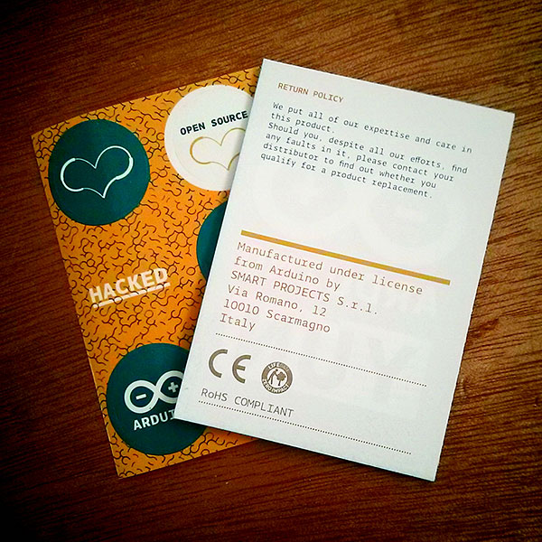
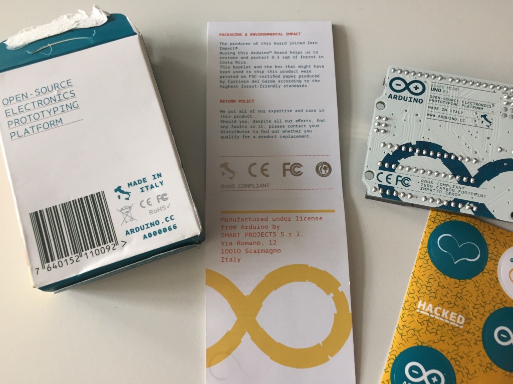
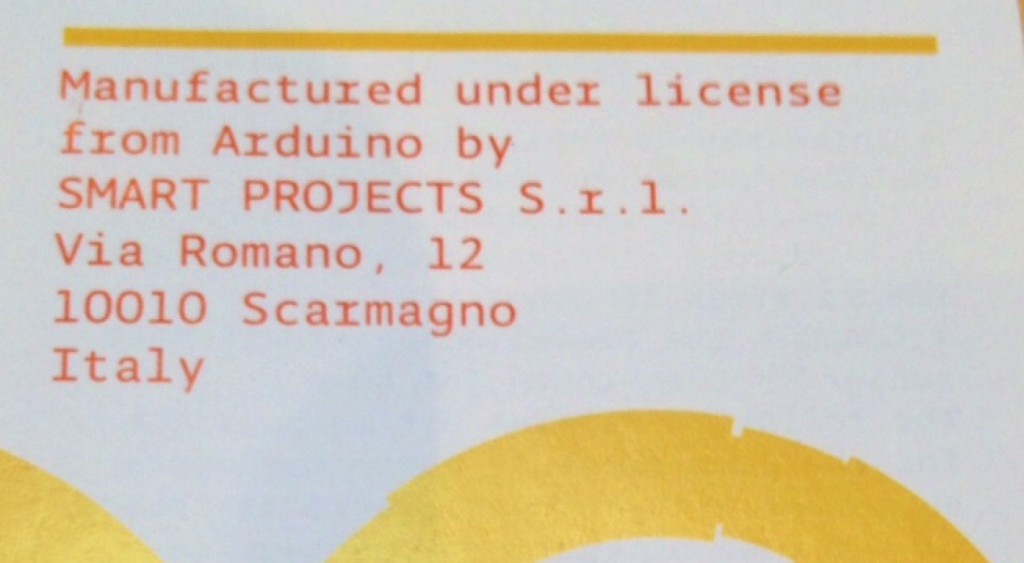
Furthermore the main manufacturer of the Arduino-branded boards in Italy – “Smart Projects S. r. L” belongs to team member Gianluca Martino, and this organisation paid royalties to the team for the right to manufacture the boards.

Moving on, in 2008 the five formed a company to hold the trademarks and so forth that would allow for more commercial opportunities with regards to licensing and so forth.

However as Massimo wrote in a recent Make: magazine article, Gianluca had registered the Arduino name in Italy amongst other nefarious actions.

To top this off, Massimo tells us that Smart Projects have stopped paying the royalties for over twelve months. This has been most disappointing as being the supplier to Arduino resellers across the globe, resellers thought they were doing the right thing by buying the real boards. A

And to add insult to injury, Smart Projects changed their name to Arduino S. r. L., and was sold by Gianluca Martino in 2014. This company has created their own Arduino website (ending with .org instead of .cc) – and even forked their own version of the IDE and given it a version number starting with 1.7, which is greater than the current 1.6.3. No doubt this will trap a few users into thinking that Arduino S. r. L. (which we’ll shorten to ASrL) is the legitimate supplier and site for Arduino. For more information about the later developments, read this article form Hackaday.

So from what we can tell, the manufacturing member of the original Arduino team has gone off and tried to replicate the Arduino ecosystem under their own terms, allegedly misappropriating the Arduino name and trademark and denying royalties – and is currently still the only source of what have always been “genuine Arduino boards”.

Wow, what a mess.

More keen observers will realise that there isn’t anything wrong with reproducing their own Arduino-compatible boards thanks to the open-source nature of the hardware, and there must be a google of copies, compatibles and knock-offs in the market. And it’s ok to fork the IDE for modify, improve or bork it up to your own requirements as long as yout stick to the original software licence.

However the alleged royalty issue and trademark and name theft is not ok. So where does this leave the Arduino team now? From what I can learn, the rest of the original Arduino team are moving forward and will continue to innovate with new devices and projects which is admirable – and they have agreed to work with manufacturer/retailers such as adafruit to produce new boards (such as the Arduino Gemma).

At this point how does this affect you, as a potential or current Arduino enthusiast? That’s an excellent question. If you have always believed in supporting the Arduino team by purchasing genuine boards – it would seem this option is no longer available until the original team find a new manufacturing partner.

And how does this affect Arduino resellers? As an Arduino reseller ourselves (tronixlabs.com) we made our position as clear as we could at the time. Our position at Tronixlabs is that we want to continue to sell boards that benefit the Arduino team, however we’re a business that aims to meet the needs of all of our customers – and thus we offer compatibles as well.

We have contacted the Arduino team for guidance about future Arduino-branded boards and await their reply. What we do look forward to, however, is a cheaper reseller cost. The freight charge from Europe plus the board costs at the time were quite extraordinary.

Furthermore if Arduino S. r. L introduce a compelling product that people want – hey we’ll sell that as well. The following day Nate from Sparkfun made a similar statement. Whether they make their thoughts public or not, we’re confident that all resellers will take a similar stand, as you don’t want to specifically pick a side in case the other side has a great product that you want to sell. Then again, why would a manufacturer hold back their product to a retailer if said retailer offers products from the competition?

As Kent Brockman would say “… only time will tell”.

From this juncture we look forward to what the Arduino team has for us in the future with great interest… and we’re also following Arduino S. r. L as well to see what they come up with.

However don’t panic – for day to day use nothing has changed for us as enthusiasts. However – do we owe the Arduino team our support? Absolutely – so many people have benefited from their original idea and work for everyone’s benefit. If you feel so inclined, you can directly donate funds to the Arduino project via the IDE download page.

Finally, a great lesson can be learned from these recent events. If your team comes up with a great idea, product or service – before you get serious spend the time and resources required to formalise ownership of intellectual property, naming rights, copyrighted work, and so forth.

We look forward to your thoughts and notes about the situation, which can be left in our moderated comment section. And finally a plug for my own store – tronixlabs.com – offering a growing range and Australia’s best value for supported hobbyist electronics from adafruit, DFRobot, Freetronics, Seeed Studio and much much more.

As always, have fun and keep checking into tronixstuff.com. Why not follow things on twitterGoogle+, subscribe  for email updates or RSS using the links on the right-hand column, or join our forum – dedicated to the projects and related items on this website.

The post Editorial – Arduino versus Arduino appeared first on tronixstuff.

Wire Your Arduino Sensors to the Cloud with Temboo Streaming

Our friends at Temboo just introduced a new way to log data from an Arduino Yún to the cloud. Called Streaming, it lets you visually select the sensors attached to your Arduino that you have gathering data, and then stream that data to the cloud IoT platform of your choice.

Streaming also makes it easy to switch where you’re sending your data once your application is running, without requiring any hardware or software updates. Right now, Streaming works with Microsoft’s Power BI and Google’s BigQuery, but Temboo will be continuing to add more platforms in the future. As with Temboo’s other Arduino programming tools, Streaming lets you generate all the code you need for your application right in your browser, and tailors that code to the parameters that you specify. It makes it much easier to store sensor data from your Arduino in the cloud, and to analyze the datasets that you build.

This video shows you how it works:

Arduino Blog 22 Apr 18:19

ASCII Art With Pure Data And A Typewriter

[vtol] is quickly becoming our favorite technological artist. Just a few weeks ago he graced us with a Game Boy Camera gun, complete with the classic Game Boy printer. Now, he’s somehow managed to create even lower resolution images with a modified typewriter that produces ASCII art images.

As with everything dealing with typewriters, machine selection is key. [vtol] is using a Brother SX-4000 typewriter for this build, a neat little daisy wheel machine that’s somehow still being made today. The typewriter is controlled by an Arduino Mega that captures an image from a camera, converts it to ASCII art with Pure Data and MAX/MSP, then slowly (and loudly) prints it on a piece of paper one character at a time.

The ASCII art typewriter was recently shown at the 101 Festival where a number of people stood in front of a camera and slowly watched a portrait assemble itself out of individual characters. Check out the video of the exhibit below.


Filed under: Arduino Hacks
Hack a Day 21 Apr 21:00

Call for Makers is open! Join Maker Faire Rome 2015

Last year Maker Faire Rome welcomed 600 projects, 200 performances, 90.000 visitors coming from all over the world.  Maker Faire Rome – The European Edition recently announced its third edition scheduled from the 16th to the 18th of October 2015 and will take place at  “La Sapienza” University in Rome, exceptionally “closed” for three days to host this international event.

The Curators of the Faire, Massimo Banzi, co-founder of Arduino and Riccardo Luna, italian Digital Champion, are inviting makers of all kinds and ages to showcase their amazing work and embrace the do-it-yourself (or do-it-together) spirit with a great and appreciative audience.

Are you a Maker, an Innovator, a digital Craftsman? The MakerFaireRome’s Call4Makers is out!

There are many ways to participate:

  • you can exhibit your project: we’ll give you a booth with table and chairs inside the halls, which will be filled with visitors who are curious and interested in meeting you
  • you can give a presentation in public: we’ll give you a room or a stage where you can talk about your project or tell your story or deal with the issues that you want to propose
  • you can hold a workshop: we’ll give you a workshop area where you can do interactive demonstrations and engage participants -adults and / or children- in practical activities
  • you can perform in public: we’ll give you a space or a stage for you to perform in your creative, technological, robotic, musical, pyrotechnic performance…

The proposals regarding the exposure of projects, if accepted, will lead to the allocation of a booth, free of charge. Presence is required at this booth while Maker Faire Rome 2015 is open to the public (three days). It will also be possible to sell products or gadgets.

Accepted projects will be valorized on the MakerFaire Rome website. Besides, Maker Faire Rome press & media team will diffuse info about participants to the newspapers, radio and television stations, which in the past years have devoted a lot of attention to the projects and performers.

We expect creative, innovative, fun, interactive projects, showing the process by which the achievements enrich visitors, communicating passion and ingenuity.

Are you thinking about participanting? In the meanwhile:

  • spread the word! #MFR15
  • help us to involve all the makers you know (and especially those who still do not know they are makers!)
  • subscribe to our newsletter to keep informed about news, events and discounts!

We are looking forward to seeing you all in Rome in October!


Want to help Arduino.CC? Take a pic of your Arduino packages!

We are posting below an interesting blogpost published on the Adafruit’s website on Sunday April 19th, and then mentioned by Hackaday.

Give it a read and use the #TeamArduinoCC tag when posting a pic of your packaging: that’s how you can show your support to Arduino.cc!

————————
Please post old Arduino packaging that says “Manufactured under license from Arduino” #TeamArduinoCC
Hey folks, as a lot of you know there’s a huge Arduino vs Arduino dispute (Hackaday / MAKE coverage / Arduino.cc). We’re currently making an official Arduino with Arduino.cc so we’re not commenting at this time for all sorts of good reasons, however, we, as in the Arduino.cc community, could use your help. If you could dig up any old Arduino packaging that has “Manufactured under license from Arduino by SMART PROJECTS” and post the photos – that could be pretty helpful for “team Arduino.cc”.

PLEASE INDICATE what country where you purchased the products in and what year!

Pictured above, an Arduino UNO from September 2014 from Becky Stern’s desk. She had it unopened and we were able to see an important detail “Manufactured under license from Arduino by SMART PROJECTS S.r.l. Via Romano, 12 10010 Scarmagno Italy.

Please post any old packaging you have from older Arduino products that also have this on Flickr, G+, Instagram, Twitter, wherever you can, you can use the tag #TeamArduinoCC to help. You can also email it to teamarduinocc@adafruit.com


Here’s a video showing where’s the sentence mentioned by Adafruit and below the #TeamArduinoCC  hashtag timeline:


#TeamArduinoCC Tweets<>