How to Easily Build a “Light Paintbrush”
 Turn a Circuit Playground into a light-generating "paintbrush" for long-exposure photography.
The post How to Easily Build a “Light Paintbrush” appeared first on Make: DIY Projects and Ideas for Makers.


Turn a Circuit Playground into a light-generating "paintbrush" for long-exposure photography.
The post How to Easily Build a “Light Paintbrush” appeared first on Make: DIY Projects and Ideas for Makers.
We’ve been waiting for this one. A worm was written for the Internet-connected Arduino Yun that gets in through a memory corruption exploit in the ATmega32u4 that’s used as the serial bridge. The paper (as PDF) is a bit technical, but if you’re interested, it’s a great read.
The crux of the hack is getting the AVR to run out of RAM, which more than a few of us have done accidentally from time to time. Here, the hackers write more and more data into memory until they end up writing into the heap, where data that’s used to control the program lives. Writing a worm for the AVR isn’t as easy as it was in the 1990’s on PCs, because a lot of the code that you’d like to run is in flash, and thus immutable. However, if you know where enough functions are located in flash, you can just use what’s there. These kind of return-oriented programming (ROP) tricks were enough for the researchers to write a worm.
In the end, the worm is persistent, can spread from Yun to Yun, and can do most everything that you’d love/hate a worm to do. In security, we all know that a chain is only as strong as its weakest link, and here the attack isn’t against the OpenWRT Linux system running on the big chip, but rather against the small AVR chip playing a support role. Because the AVR is completely trusted by the Linux system, once you’ve got that, you’ve won.
Will this amount to anything in practice? Probably not. There are tons of systems out there with much more easily accessed vulnerabilities: hard-coded passwords and poor encryption protocols. Attacking all the Yuns in the world wouldn’t be worth one’s time. It’s a very cool proof of concept, and in our opinion, that’s even better.
Thanks [Dave] for the great tip!


A few days ago, we launched the MKR2UNO Adapter, which enables you to easily turn an Arduino Uno form factor project into a MKR1000-based one. Simply mount your IoT board to the adapter, plug in any Uno shield and have a wireless device in no time.
Our newly-published tutorial provides a step-by-step overview of how to build a WiFi-controllable robot using the MKR2UNO Adapter with a MKR1000 and an Arduino Motor Shield.
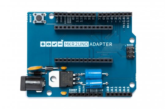
This project combines the Arduino MKR1000’s web server and Arduino Motor Shield’s capabilities to drive a pair of different DC motors. A basic interface is hosted and hard-coded in the MKR1000, allowing the user to maneuver the robot up, down, left or right.

If you grew up in ’80s or early ’90s and owned a Nintendo system, chances are you’ve played Duck Hunt. In the classic light gun shooter video game, players would aim their NES Zappers at duck targets as they appeared on the TV screen. So what do you do when you still own the once-popular accessory? If you’re Warner Skoch, you turn it into a controller for your lamp and small devices.
The setup consists of a couple Arduino Pro Minis. Skoch embedded one board in the Zapper with an IR emitter and another in a box with an IR receiver, which also has an outlet for him to plug in his lamp or other gadget.
The receiver watches for a signal from the Zapper, which then triggers the relay inside the box on and off. The actual IR receiver part is separate, however, mounted behind a Duck Hunt duck made from Perler beads.
Spark up some NES nostalgia and watch Skoch’s project in action below!
[domiflichi] is human and fallible. So he can’t be blamed for occasionally forgetting the laundry in one of the machines and coming back to a less than stellar result. However, while fallible, he is not powerless.
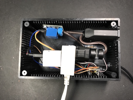
What if his washer/dryer could email or text him about his laundry? It seemed simple enough. Add a vibration sensor to the side of the machine along with some brains. When the load is done it will bother him until he comes down to push the button or There Will Come Soft Rains.
 He started off with an Arduino-and-ESP8226 combination and piezo sensors. The piezos had lots of shortcomings, so he switched to accelerometers and things worked much better. We really like the way he mounts them to the side of the washer dryer using the PCB’s mounting screws as angle brackets. The case is a standard project box with some snazzy orange acrylic on the front.
It took some fiddling, but these days [domiflichi]’s clothes are fresher, his cats fed, and his appliances more aware. Video of it in operation after the break.


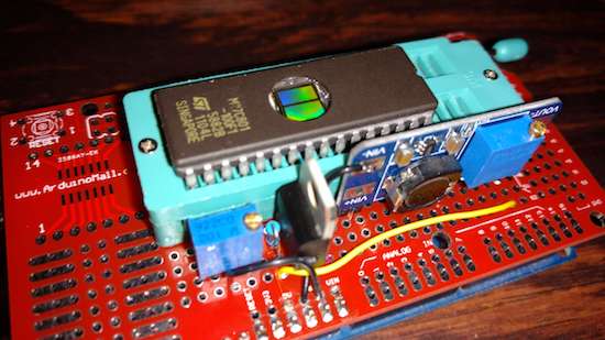
If you’ve got a cartridge-based gaming system, this EPROM burner will let you load whatever game you want!
Robson Couto recently acquired an old SNES. A great console for its time, but it only came with one cartridge, a bootleg copy of Mortal Kombat. Legalities aside, he decided that he would experiment with his own bootleg cartridge creator via an EPROM burner made as an Arduino Mega shield.
His process involves finding an unwanted game cartridge (he prefers sports, though your results may vary), burn the ROM, then exchange the cartridge ROM for the newly-burned ROM.

According to Couto, EPROM is “easier to program than flash.” and you can see how he did it on his blog post here. Code for the project is also available on GitHub.
“The great thing about standards is that there are so many to choose from.” Truer words were never spoken, and this goes double for the hobbyist world of hardware hacking. It seems that every module, every company, and every individual hacker has a favorite way of putting the same pins in a row.
We have an entire drawer full of adapters that just go from one pinout to another, or one programmer to many different target boards. We’ll be the first to admit that it’s often our own darn fault — we decided to swap the reset and ground lines because it was convenient for one design, and now we have two adapters. But imagine a world where there was only a handful of distinct pinouts — that drawer would be only half full and many projects would simply snap together. “You may say I’m a dreamer…”
This article is about connectors and standards. We’ll try not to whine and complain, although we will editorialize. We’re going to work through some of the design tradeoffs and requirements, and maybe you’ll even find that there’s already a standard pinout that’s “close enough” for your next project. And if you’ve got a frequently used pinout or use case that we’ve missed, we encourage you to share the connector pinouts in the comments, along with its pros and cons. Let’s see if we can’t make sense of this mess.
The de-facto standard for a hacker’s TTL serial pinout is definitely the layout that FTDI uses for their USB/TTL serial cables. Said cable is just so handy to have on hand that you’d be silly to use any other pinout for the job. And the good news is that the rest of the world has basically joined in. From the Chinese “Pro Mini” cloneduinos to the Hackaday Edition Huzzah ESP8266 board, and from Adafruit’s FTDI Friend to Modern Device’s USB-BUB, almost everyone uses this pinout. A victory for the common man!

There is one slight point of contention, however, and that’s whether pin 6 is DTR or RTS#. We never use either, so we couldn’t care less, but if you’re counting on your programmer sending the DTR signal to enter programming mode on the device (we’re looking at you Arduino!) then you’ll want DTR on pin 6, and the original FTDI cable, ironically, has the “wrong” pinout. Perhaps that’s why Sparkfun avoided the whole debacle and went their own way, breaking out every signal off the FTDI chip into their own unique configuration.
If you’re only going to break out TTL serial lines, you’d be a fool to use any other pinout.
Unlike the case with simple serial, connecting various kinds of modules to mainboards is a difficult problem. Creating a single pinout or connector specification for many potential protocols or arbitrary signals is a Herculean task. Surprisingly, it’s been done a few times over. Here are some notables.
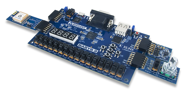
Digilent makes a wide range of FPGA demo boards, and they needed an in-house standard pinout that they could use to plug into various add-on peripheral modules that they sell. Thus Pmod was born. It has since become a full-fledged, and trademarked, open standard that you can use in your designs. Here’s the PDF version of the specification for you to print out, so you know they mean business.
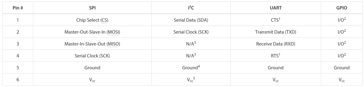
 There are a few aspects of Pmod that we think are particularly clever. First, the number of pins involved is “just right” at six, and it’s easily expandable. They use standard 0.1″ pitch pins and headers. Two lines carry power and ground, leaving four free pins for SPI, UART, or whatever else. The specification is that all power and signal voltages are 3.3 V because they’re designed for FPGAs after all. You can mix and match if you know what you’re doing, but they won’t let you call it Pmod(tm).

If you need more than four signals, there’s a twelve-pin version which is just two six-pin Pmods stacked into a double-row header. The extra power and ground are redundant, but it makes a twelve-pin output very flexible, because nothing stops it from being used as two sixes. The standard also says that the twelve-pin headers are to be spaced at 0.9″ center-to-center, so you can even connect two of them together when you need sixteen board-to-board signal connections. We like the modularity and expandability.
Pmod connectors are multi-protocol, but for each protocol there is a single pinout. So there’s an SPI Pmod and an I2C Pmod, and the pins are always in the same place. There isn’t a Pmod standard for every conceivable application, of course, so there’s a GPIO pinout that gives you free rein over what goes where. We think that it would be nice if some additional notable protocols (I2S? one-wire? servos? analog stereo audio?) were included in the specs, but the community can also handle these lower-level details.
 In our eyes, Pmod is nearly perfect. It uses cheap hardware, is easily expandable, and the smallest incarnations are small enough to fit on all four sides of a one-inch-square board. If you’re willing to pay the brand-name premium, Digilent makes an incredible range of modules. We want to see more hackers outside of the FPGA scene get on it.
 What Digilent is to development boards in the US, MikroElektronika is in Europe. While Pmod aims to be capable of doing anything, Mikro-E’s mikroBUS connector wants to do everything, which is to say it has I2C, SPI, UART, two voltages, and even a few extra signals all on the same pinout. Physically, it’s two single rows of eight pins, spaced 0.9″ apart side-to-side, which means it fits into a breadboard nicely. Here’s the spec in PDF.
The tradeoff here, relative to Pmod, is that a lot of pins go unused on any given design. With (only) one “analog” channel, you wouldn’t choose mikroBUS to send stereo audio, whereas nothing stops you from calling the Pmod’s GPIO lines analog and sending four channels of sound. But that mikroBUS gains is fool-proofness. (Well, they could have also made it asymmetric…) There’s no chance of a newbie plugging an SPI module in where an I2C module is expected and scratching their heads. With mikroBus, it should just work.
Microchip has added a mikroBus port to their Curiosity boards, and MikroElektronika makes a ton of modules. If your audience consists of beginners, and one footprint for all protocols, it’s worth considering.
 Meanwhile in China, Seeed Studios makes open-source modules, and makes them cheap. Their Grove connector uses only four pins, with power and ground among them. The have standard pinouts for UART, I2C, and for servo motors. Sensors and other analog peripherals are allocated one “primary” pin and one “secondary” and it’s assumed that you know what you’re doing. The idea behind their system is that you add a shield to your microcontroller board, and they break out the relevant pins into these four-pin Grove headers.
This is great for small things and I2C devices, which is Seeed’s catalog, but there just aren’t enough signal pins to run SPI or an analog RGB LED, for instance. But because of the small number of pins, they use very inexpensive polarized cables and shrouds that you can’t plug in the wrong way, and that take up relatively little board space. That’s Grove’s design trade-off.

Hobby servo motors need three wires: voltage, ground, and a signal to tell them where to point. There are three distinct ways to arrange these wires, but Futaba, HiTec, Tower, GWS, and JR servos all chose to put them in SVG (or GVS) order, and there’s no reason to buck the trend. (Airtronics, what were you thinking?!)
SVG is also a handy pinout to use for all sorts of one-signal sensors or actuators where space is a premium, and we’ve seen this in a few designs (here and here, for instance). But we’re torn. Relative to the Grove, for instance, you’re just saving one pin. Even the Pmod would work with only three pins’ overhead. Is that worth complicating your life with another pinout? If you need a lot of powered one-signal devices, or servos, it probably is, and you can hardly beat SVG or GVS, whichever way you look at it.
Viewed in the light of any of the other module interconnection systems, the Arduino is the worst of all worlds. It’s monolithic like mikroBUS, but it’s gigantic — you have to build a 55×73 mm board and accommodate 30 pins and pass-throughs if you’d like it to be stackable. The pins have a funny spacing (that gap!), that doesn’t fit any normal protoboard. Nobody goes through the trouble of building a shield just for an I2C connection. No wonder most Arduino projects look like a breadboard hedgehog. About the only good thing we can say about it is that it’s hard to plug one in backwards.
There’s also the tiny little factor that there’s a million Arduino shields out there, a huge community built around them, and widespread support for them. Which turns out to trump all of the reasonable design concerns. (Shakes head.)
 Of course, there are other very specific pinouts that one might encounter, like the old ESP-01 module, or the XBee, or the nRF24. Adapting modules to fit boards is always going to be a pain, because the manufacturers will pick whatever suits them on that day. Programmer pinouts for specific microcontrollers are a similar story, as is JTAG, which is a beautiful standard with a dogs’ breakfast of pinout possibilities. (We could do a whole column!)
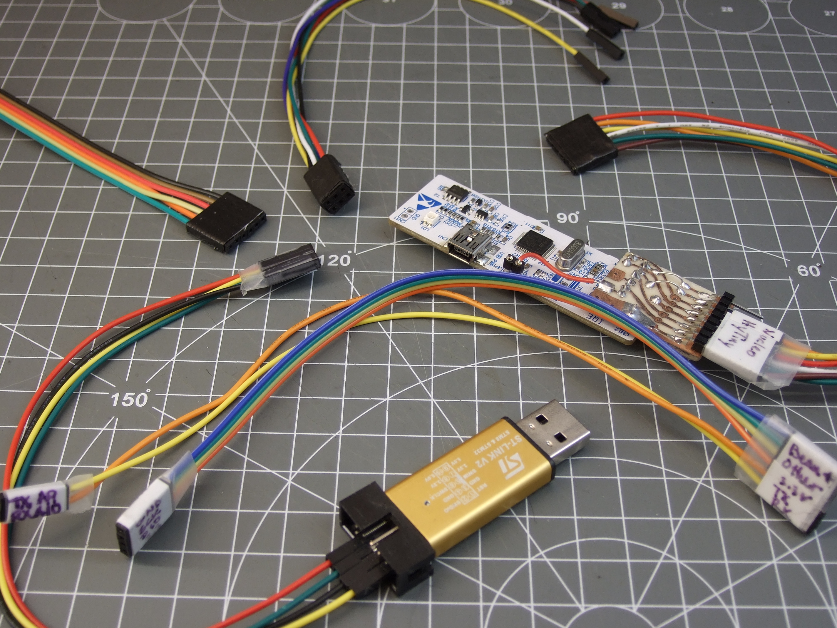
Faced with this inevitability, and the need for many one-off adapters, what can you do? What we do is buy a lot of those cheap “Dupont” female-to-female cables, get the connections working and tested, and then tape them permanently together and label them. It’s not as pretty as a dedicated PCB adapter, but it’s quick and easy and gets you moving on to what you wanted to do in the first place.
The goal of connectors, and their standards, is putting parts together. If you’re designing a sensor module with more than a couple components, and you want it to be maximally easy for yourself and others to hook up to whatever mainboard they’ve got, this is no easy task. The end result is a proliferation of translators, adapter boards, hats, shields, capes, or whatever else. We have a drawer and a half full, and we bet you do too.

What’s your solution to the ultimate connector conundrum? Are there important connector systems that we’ve left out? What are their design tradeoffs? How stoked would you be if things could just plug together? Let us know!
Thumbnail image courtesy of [Raspberry Pi Controller].


With a speaker on the back and a drum machine on the front, what can possibly go wrong?
After riding his bike home after a synthesizer get together, Sam Battle decided to actually combine these two pursuits, transforming an iconic 1973 Raleigh Chopper into a mobile synthesizer. Though his first try was rather crude, using an Oyster card stuck between spokes to trigger a switch, his aptly named “Synth Bike 2.0” looks pretty awesome.
Featuring eight–yes eight–Arduino Nano boards, the music’s tempo can be controlled by how fast you pedal, or set up to use a built-in clock. Other electronics include a Sparkfun WAV Trigger, some analog synth circuitry, a sampler, a digital oscillator, and a Music From Outer Space Echo module.

Plenty of switches, dials, pads and knobs can be found on a control box mounted to the handlebars, while more pads are located on the bike’s top tube.
As awesome as it looks, all of this electronic gear seems to suck a lot of power, and it can only play for around 10 minutes at a stretch. A battery upgrade, however, is reportedly imminent!

Over the last couple of years, cat videos have become the undisputed champions of the web. Whether it’s kittens playing with their shadows to failed jump attempts to giving each another massages, we’re all guilty of watching a few of these clips from time to time (yes, even at work). Built with this in mind, oCat is a real-time tracker for feline-related activity on the Internet.
oCat consists of two parts: the oCat News Distractor and the Kitty o’Cat Twitter bot. Using Google’s YouTube API, the system works by continuously monitoring for new uploads, the number of new views each day, or a specific video that has received a remarkable amount of attention. It then tweets these stats and prints them out on thermal paper, stamping a paw print on the timeline for every 1,000 views.
Created by Annika Engelhardt, a digital media design master’s student at the University of the Arts in Bremen, oCat uses an Arduino along with an ESP Wi-Fi module, a servo, and an LCD screen. The aim of the project is to increase and reveal the amount of hours people spend watching cat videos online.
The cat is an altered Maneki-neko, holding a stamp using welding wire and hot glue. Even though I filled the stamp with extra ink, it did not work properly and I had to cut out the paw-shape from a sponge and glue it onto the original stamp.
The thermal printer used in the device needs a USB connection, so I used a Raspberry Pi to control it. I wrote a Python script that checks four different RSS news feeds for new posts every 15 minutes and prints one headline with a timestamp every minute.
The Twitter bot was programmed using Python and a library called tweepy. Most of the script is reading JSON files, juggling and comparing data and text files and in the end mixing up parts of a sentence to form a tweet. The bot will be enhanced in the future

Engelhardt exhibited the project at Galerie Flut in Bremen back in October. You can find more pictures and information on the project here.
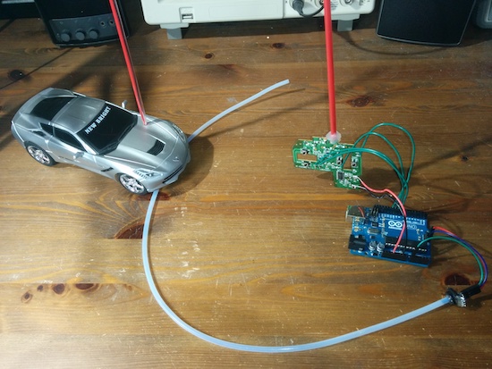
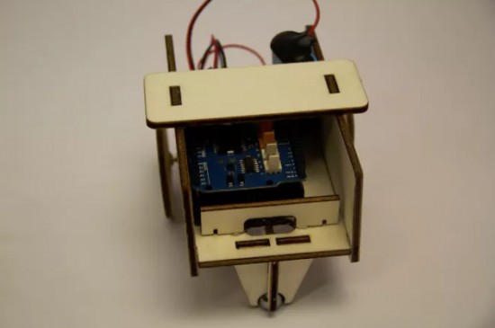
These toy cars are modified for sip-and-puff controls, where one lightly sucks or blows air as an interface.
If you have certain disabilities, use of your hands can be difficult if not impossible. An alternative is an interface known as sip-and-puff, which allows for control of electronics by producing a small air flow with your breath. In the build shown in the videos below, Bob Paradiso integrated this type of command into two types of RC vehicles.
To operate the first vehicle, one simply uses puffs to go forward, while sips make the car go backwards. The second is much more advanced, with a double-puff making the car go forward, a double-sip for backwards, and single puffs and sips to turn left or right.
There are many sip-and-puff controls on the market for various things, but they can be expensive or difficult to customize. What I’m showing here is an extremely affordable, simple to build, and fully customizable sip-and-puff setup used to control two different remote control toys that have very different controls.
You can see Paradiso’s writeup here and check out the code on the project’s GitHub page.