WiFi and Bluetooth were never meant to be the radios used by a billion Internet of Things hats, umbrellas, irrigation systems, or any other device that makes a worldwide network of things interesting. The best radio for IoT is something lightweight which operates in the sub-Gigahertz range, doesn’t need a lot of bandwidth, and doesn’t suck down the power like WiFi. For the last few years, a new low-power wireless communication standard has been coming on the scene, and now this protocol — LoRa — will soon be available in an Arduino form factor.
The Primo, and NRF
It’s not LoRa, but the Arduino Primo line is based on the ESP8266 WiFi chip and a Nordic nRF52832 for Bluetooth. The Primo comes in the ever-familiar Arduino form factor, but it isn’t meant to be an ‘Internet of Things’ device. Instead, it’s a microcontroller for devices that need to be on the Internet.
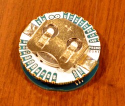
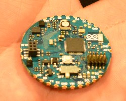
Also on display at CES this year is the Primo Core which we first saw at BAMF back in May. It’s a board barely larger than a US quarter that has a few tricks up its sleeve. The Primo Core is built around the nRF52832, and adds humidity, temperature, 3-axis magnetometer and a 3-axis accelerometer to a square inch of fiberglass.
The Primo Core has a few mechanical tricks up its sleeve. Those castellated pins around the circumference can be soldered to the Alice Pad, a breakout board that adds a USB port and LiPo battery charger.
LoRa
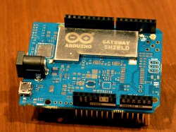
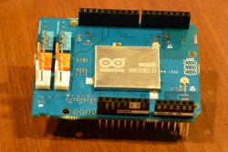
Also on deck at the Arduino suite were two LoRa shields. In collobration with Semtech, Arduino will be releasing the pair of LoRa shields later this year. The first, the Node Shield, is about as simple as it can get — it’s simply a shield with a LoRa radio and a few connectors. The second, the Gateway Shield, does what it says on the tin: it’s designed to be a gateway from other Arduino devices (Ethernet or WiFi, for example) to a Node shield. The boards weren’t completely populated, but from what I could see, the Gateway shield is significantly more capable with support for a GPS chipset and antenna.
A partnership with Cayenne and MyDevices
Of course, the Internet of Things is worthless if you can’t manage it easily. Arduino has struck up a partnership with MyDevices to turn a bunch of low-bandwidth radio and serial connections into something easy to use. Already, we’ve seen a few builds and projects using MyDevices, but the demos I was shown were extremely easy to understand, even if there were far too many devices in the room.
All of this is great news if you’re working on the next great Internet of Things thing. The Primo Core is one of the smallest wireless microcontroller devices I’ve seen, and the addition of LoRa Arduino shields means we may actually see useful low-bandwidth networks in the very near future.
Sure, if you’re going to get a new ride, a model from the twenty-teens would be nice, but for hacking purposes, the simplicity of an older cars makes modification fairly simple. It also makes hot-wiring easy, and as they don’t generally have an alarm system, these vehicles are often targets for theft.
After his friend’s VW Beetle was stolen, Instructables user Ben Schroeder (aka “Pantopush”) decided that he needed to protect his 1966 Bug. So, as any Maker would do, he took matters into his own hands with a GPS-enabled Arduino Uno in a locked glove compartment.
Now, unless the unit is turned off, if it detects that the car is moving, it uses a relay to switch the horn on. Simple, effective (hopefully), and could be expanded to flash the lights or even text the owner with the location of the car.
Turning an Arduino of virtually any sort into a simple AVR 6-pin ISP programmer is old hat. But when Atmel came out with a series of really tiny AVR chips, the ATtiny10 and friends with only six pins total, they needed a new programming standard. Enter TPI (tiny programming interface), and exit all of your previously useful DIY AVR programmers.
[Kimio Kosaka] wrote a dual-purpose TPI and ISP firmware for the ATmegaxxUn chips that are used as a USB-serial bridge on the Unos, and constitute the only chip on board a Leonardo or Micro. The catch? You’re going to have to do a little bit of fine-pitch soldering. Specifically, [Kosaka-san] wants you to get access to an otherwise obscured signal by drilling out a via. We’d do it just for that alone.
The rest of the procedure is to flash a DFU USB bootloader into the Arduino, then load up the flash-programmer code. Your former Arduino is now capable of flashing both old-school ISP AVR chips, as well as the tiny little ones that require TPI.
If you’re having deja vu, yes we have covered a DIY TPI programmer before, but it required a bespoke uploader software on your host computer. [Kosaka]’s version appears to the host as an Atmel programmer, and you can use any of the standard tools. And you get to try your hand at some fun fine-pitch solder work. That’s win-win!
The next time you and your friends want to see who can chug beer (or a non-alcoholic beverage for the younger crowd) the fastest, you may want to try building your own Cider Racer 2600–an electronic racing platform and timer for competitive drinking.
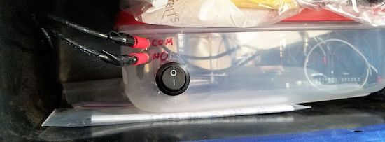
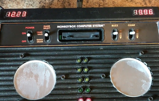
Created by YouTuber “MonkeyBOX Entertainment” for an annual Christmas party, the project consists of a broken Atari 2600 retrofitted with an Arduino Mega, two 4-digit 7-segment displays, some LEDs, wires, and other miscellaneous parts. A pair of custom coasters were constructed using force-sensitive resistors, soft springs, rubber actuators, and three layers of CNC-cut materials: acrylic bottom plate, brushed aluminum center, and acrylic spacer to make it level with top of the old gaming console.
In drag race mode, two drinks are placed on the Cider Racer 2600’s pressure-sensing coasters. When ready to get things underway, both competitors press a red button on the side, prompting LEDs begin to countdown from red to green as if they were cars waiting at the starting line. Time is shown on a 7-segment display above each coaster, which stops as soon as someone puts down their empty glass. The winner’s time will then flash.
The clock can be cleared using the Atari’s old ‘game reset’ switch. But that’s not all. The Cider Racer 2600 is capable of detecting false starts and if a drink is placed back prematurely. You can read more about the project in the video’s description below, and check out its popular reddit thread here.
The next time you and your friends want to see who can chug beer (or a non-alcoholic beverage for the younger crowd) the fastest, you may want to try building your own Cider Racer 2600–an electronic racing platform and timer for competitive drinking.
Created by YouTuber “MonkeyBOX Entertainment” for an annual Christmas party, the project consists of a broken Atari 2600 retrofitted with an Arduino Mega, two 4-digit 7-segment displays, some LEDs, wires, and other miscellaneous parts. A pair of custom coasters were constructed using force-sensitive resistors, soft springs, rubber actuators, and three layers of CNC-cut materials: acrylic bottom plate, brushed aluminum center, and acrylic spacer to make it level with top of the old gaming console.
In drag race mode, two drinks are placed on the Cider Racer 2600’s pressure-sensing coasters. When ready to get things underway, both competitors press a red button on the side, prompting LEDs begin to countdown from red to green as if they were cars waiting at the starting line. Time is shown on a 7-segment display above each coaster, which stops as soon as someone puts down their empty glass. The winner’s time will then flash.
The clock can be cleared using the Atari’s old ‘game reset’ switch. But that’s not all. The Cider Racer 2600 is capable of detecting false starts and if a drink is placed back prematurely. You can read more about the project in the video’s description below, and check out its popular reddit thread here.
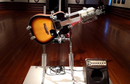
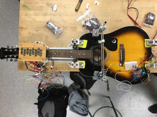
Inspired by a statement written on Woody Guthrie’s guitar, This Machine Kills Fascists (TMKF) is an Arduino Mega-based, guitar-playing robot that performs traditional American folk music on a portable stage. Sheet music with the song lyrics are printed and left on the benches set up in front of the stage, while audience members are encouraged to sing along to the tunes.
Developed by engineer Dustyn Roberts, artist Troy Richards, and designer Ashley Pigford, TMKF is combines the analog tradition of folk music and digital technology of robotics.
Our project is inherently positive and seeks to bring people together through music. It uses a strategy of generating empathy and goodwill with an artificial intelligence to make us ask questions of the kind of community we may or may not be making with actual humans. With TMKF we hope to create a compelling experience that starts conversations.
2016 was a great year for Open Hardware. The Open Source Hardware Association released their certification program, and late in the year, a few silicon wizards met in Mountain View to show off the latest happenings in the RISC-V instruction set architecture.
The RISC-V ISA is completely unlike any other computer architecture. Nearly every other chip you’ll find out there, from the 8051s in embedded controllers, 6502s found in millions of toys, to AVR, PIC, and whatever Intel is working on are closed-source designs. You cannot study these chips, you cannot manufacture these chips, and if you want to use one of these chips, your list of suppliers is dependent on who has a licensing agreement with who.
We’ve seen a lot of RISC-V stuff in recent months, from OnChip’s Open-V, and now the HiFive 1 from SiFive. The folks at SiFive offered to give me a look at the HiFive 1, so here it is, the first hands-on with the first Open Hardware microcontroller.
Before I dig into this, I must discuss the openness of the HiFive 1, and RISC-V in general. Free Software and Open Hardware is a religion, and it’s significantly more difficult to produce Open Hardware than Free Software. No matter how good or how Open the design is, the production of the first Open Source microcontroller will generate far too many comments from people who use the words ‘moral imperative’ while citing utilitarian examples of why Open and Libre is good. You should ignore these comments, but not just because these people have only read the back cover of the Cliff’s Notes for Philosophy For Dummies.
The Openness of the HiFive 1 and RISC-V
The biggest selling point for RISC-V chips is that there are no licensing fees, and this microcontroller is Open Source. This is huge — your AVRs, PICs, ARMs, and every other microcontroller on the planet is closed hardware. You can’t study the silicon. If we’re ever going to get a completely Open Source computer, it has to start somewhere, and here it is.
With that said, this is an Arduino-compatible board with an FTDI chip providing the USB to serial conversion. If we had a facepalm emoji, we’d use it here. An FTDI chip is not Open Source, and they have designed drivers to break chips that aren’t theirs. The design files for the HiFive 1 were made with Altium, a proprietary and non-Free software.
This was the best picture for this section of content.
Will Stallman ever say the HiFive 1 is Free as in speech? Absolutely not. Instead, the HiFive 1 is an incrementally more Free microcontroller compared to a PIC, ARM, or AVR. There will be people who will argue – over the Internet, using late-model Intel processors with Management Engines — this is insufficient to be called Free and Open Source. To them, I will simply link to the Nirvana fallacy and ask them to point me to a microcontroller that is more Free and Open Source. Let’s not cut down the idea of an Open Source microcontroller because it’s not perfect on the first release.
Speed: 320+ MHz (the stock frequency seems to be about 256 MHz, this can be changed)
Performance: 1.61 DMIPs/MHz
Memory: 16 KB Instruction Cache, 16 KB Data Scratchpad
Other Features: Hardware Multiply/Divide, Debug Module, Flexible Clock Generation with on-chip oscillators and PLLs
Operating Voltage: 3.3 V and 1.8 V
Input Voltage: 5 V USB or 7-12 VDC Jack
IO Voltages: Both 3.3 V or 5 V supported
Digital I/O Pins: 19
PWM Pins: 9
SPI Controllers/HW CS Pins: 1/3
External Interrupt Pins: 19
External Wakeup Pins: 1
Flash Memory: 128 Mbit Off-Chip (ISSI SPI Flash)
Host Interface (microUSB): Program, Debug, and Serial Communication
Basically, the HiFive 1 is the SiFive FE310 microcontroller packaged in an Arduino Uno form factor. The pin spacing is just as stupid as it’s always been, and there is support for a few Adafruit shields sitting around in the SDK.
There are no analog pins, but there are two more PWM pins compared to the standard Arduino chip. The Arduino Uno and Leonardo have 32 kilobytes of Flash, while the HiFive 1 has sixteen Megabytes of Flash on an external SOIC chip.
The HiFive 1 supports 3.3 and 5V I/O, thanks to three voltage level translators. The support for 5V logic is huge in my opinion — nearly every dev board manufacturer has already written off 5V I/O as a victim of technological progress. The HiFive doesn’t, even though the FE310 microcontroller is itself only 3.3V tolerant. It should be noted the addition of the voltage level translators add at least a dollar or two to the BOM, and double that to the final cost of the board. It’s a nice touch, but there’s room for cost cutting here.
Other than that, the only other chip of note on the board is the FTDI FT2232HL, a well-supported but most certainly not Free and Open Source USB to UART chip. This is a two-port chip that provides programming, serial, and debug connections simultaneously.
Getting Started With The HiFive 1
The folks at SiFive realize documentation and SDKs are necessary to turn a chip into a development board. To that end, they have a bare-metal SDK and support for the Arduino IDE. The board itself comes with a bootloader, and when you plug the HiFive 1 into a USB you get the equivalent of the Blink sketch from the Arduino. Yes, you too can have Open Source blinkies. What a magical time to be alive.
Right now there are two methods of programming the HiFive 1. The Freedom E SDK, and the Arduino IDE. The Arduino IDE appears to be dependent on the Freedom E SDK, so either way, you’ll have to get the SDK running.
Right now, the SDK only works under Linux (and OS X, and possibly Cygwin), but support for Windows is coming. For Linux users, the getting started guide is more than sufficient, although it will take quite a while (at least 30 minutes) to build all the tools.
Once the Freedom E SDK is installed, support for the Arduino IDE pretty much falls into place. You’ll have to futz around with the Boards Manager, but with a few clicks, you get something fantastic. You can blink an LED with Open Source Hardware.
Actually Programming the Thing
Blinking an LED is proof enough this can be programmed, but what about the vast SDK we had to install before getting the Arduino IDE working? Here, too, it’s pretty easy to get the SDK up and running:
For this example, I simply changed the ‘hello world’ program shipped with the SDK to a ‘hello Hackaday’ program, compiled it, and ran it. Yes, someone as dumb as me can compile and upload a program to the HiFive 1.
This Stuff is Still New, Okay?
Before receiving the HiFive 1, I originally planned to benchmark this dev board against other small, common dev boards. The SDK comes with a Dhrystone program, making this the obvious choice. The results were not good, but this isn’t a reflection of the power of the FE310 microcontroller. Allow me to present the shocking infographic you should not pay attention to:
Ignore this infographic
This test used this Dhrystone Arduino sketch with the Arduino Micro, HiFive 1, and the Teensy 3.6. As you would expect the Arduino Micro performed poorly (but still ten times faster than a mainframe from 1988), and the Teensy 3.6 was extremely fast. According to this benchmark, the HiFive 1 did terribly at barely twice the computing power of the Arduino while running 16 times faster. If this benchmark was accurate, it would immediately spell the end of the RISC-V ISA.
The above benchmark is not accurate, and the poor Dhrystone performance was due to incorrect assumptions about the timer’s frequency. I plopped this problem up on the SiFive forums, and a patch was available in a few hours. What does the real benchmark say?
That’s a fast microcontroller. RISC architecture is gonna change everything.
I love this test. Beginning this review, I originally planned to run a few benchmarks on an Arduino, a Teensy, and the HiFive 1, throw together a graph and spend a hundred or so words on the results. I got so much more.
Right off the bat, we can see the HiFive 1 is fast. Really, really fast. Right now, if you want to build a huge RGB LED display, you have one good option: the Teensy 3.6. If you need a microcontroller to pump a lot of data out, the Teensy has the power, the memory, and the libraries to do it easily. In this small but very demanding use case, the HiFive 1 might be better. The HiFive 1 has more Flash (although it’s an SPI Flash), it has DMA, and it has roughly twice the processing power as the Teensy 3.6. This could be very, very cool, and I can’t wait to see the real life examples of how much the HiFive 1 can push out of its pins.
There’s your hundred word review on the performance of the HiFive 1 based on synthetic benchmarks. However, getting this benchmark working revealed far more about the state of the HiFive’s software, and how much support SiFive is throwing at it.
Admittedly, I do have a very early version of this board, and the CrowdSupply campaign for the HiFive 1 was only funded last week. No one would expect one of the three demo apps shipped with a newly released board with a mature architecture to be completely broken (unless it’s an Allwinner chip, but whatever). Very few people would expect the devs to get a patch out in less than 24 hours in response to a random person on a support forum.
All of this circles back to a single observation on the HiFive 1: It’s new. The HiFive 1 and all RISC-V microcontrollers don’t have a vast market share, user base, or decades of work behind them. However, the SiFive team seems to be taking their work seriously. They’re fixing the problems they have, and they’re constantly pushing out new documentation. This is great, and a very good indication of how much support the RISC-V chips from SiFive will have.
Chips As A Service
I should note that the folks at SiFive aren’t in the business of building RISC-V Arduino boards. They’re in the business of making chips for people. This is custom silicon we’re talking about here.
The easiest parallel to draw is between SiFive and OSH Park. These companies don’t have their own manufacturing capability; the value is in connecting end users (engineers, startups) to manufacturers. OSH Park connects you to a board house that really knows purple, and SiFive connects you to a chip fab. In the case of the FE310, that’s TSMC.
For anyone who wants silicon you can study, this is great. No, it’s not as simple as sending a board off to a fab house, but it’s a start. The fact that SiFive chose to start with Open Hardware is great, and we can’t wait to see the other hardware made with their sweat and hydrofluoric acid.
It’s a Beginning
At the base level, the HiFive 1 is a powerful microcontroller with a lot of Flash, with support for hundreds of Arduino libraries. That’s great, and alone this might be worth the $60 price of admission.
However, the big story here is the Openness of the HiFive 1. Is it completely open? No. the HiFive 1 itself uses an FTDI chip, and I’ve heard rumor and hearsay the FE310 chip has proprietary bits that are ultimately inconsequential to the function of the chip. A strict interpretation of Open Hardware will not allow this board to be called Open Hardware. Those who advance this interpretation are dumb, and to counter this argument I will quote the man himself:
…We need to distinguish levels in the design of a digital product (and maybe some other kinds of products). The circuit that connects the chips is one level; each chip’s design is another level. In an FPGA, the interconnection of primitive cells is one level, while the primitive cells themselves are another level. In the ideal future we will want the design to be free at all levels. Under present circumstances, just making one level free is a significant advance.
– Richard M. Stallman, Free Hardware And Free Hardware Designs
A design that fails to be completely Open does not deserve to be grouped with designs that are explicitly closed.
Nevertheless, this is the best we have so far, and it is only the beginning. We’re going to have more microcontrollers that are more Open, but until then, the HiFive 1 is actually a pretty cool board.
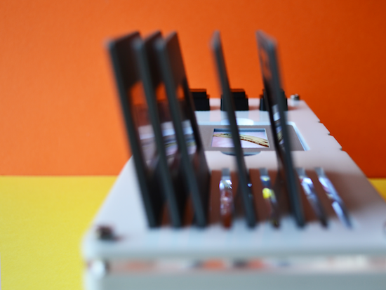
“I’m a big fan of digital music, especially Spotify. The ability to dial-up a much loved song I’ve not heard for ages or discover new music are just some of the benefits I never tire of,” writes UK-based designer Brendan Dawes. “Yet the lack of physicality to this digital medium has always left me wanting. I still own vinyl and a turntable and I love the ritual of physically flicking through what to place on the platter and then wait for the needle to drop on the spinning vinyl.”
To bridge the gap between the digital and analog worlds, Dawes decided to create what he calls the “Plastic Player.” The playful interface features a Raspberry Pi running Pi MusicBox connected to his 50-year-old B&O stereo, and an Arduino Yún with an NFC shield.
The “albums” themselves are made from a box of slide mounts with tiny NFC stickers on the back. When Dawes drops one in place, the Arduino identifies the tag, matches it to a specific record, turns on a backlight, and then communicates via WiFi with the Pi MusicBox API to play the tunes.
Removing the cartridge from the device pauses the track. But that’s not all. There are also three buttons on top, which can be used to skip, go back, or stop a song.
It’s often easy to romanticise the past, convincing ourselves that things were better back then when really I think that’s just not the case. I’ve discovered way more music since moving to Spotify then I ever did in record shops. What I do like though is the physicality of choosing an album to play and this system is an attempt to blend the good parts of both worlds. The future will continue to be digitised and I embrace that, but I think there’s a space in between the digital and the analog to create interactions that are filled with the inconvenience of what it is to be human.
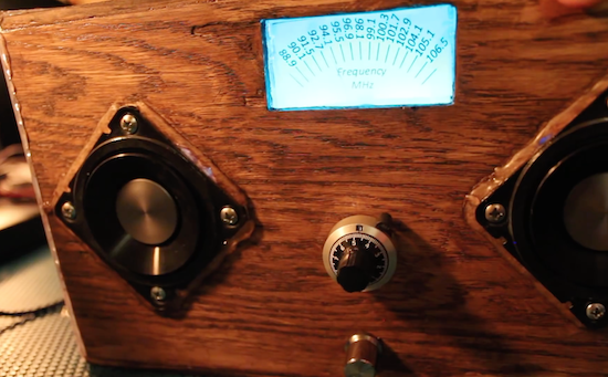
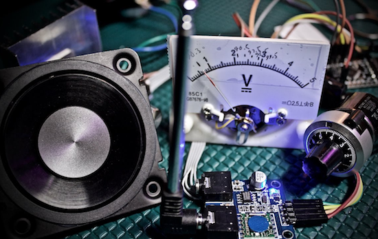
After not having an FM radio to listen to NPR, electrical engineer Kevin Darrah decided to build his own from spare parts.
Like many electronics hackers, Darrah tends to buy random components off of eBay. After all, you may need them at some point, and while cheap, sometimes they take a very long time to arrive. Unlike many of us, however, he actually found a use for several of these items, turning them into an FM radio controlled by an Arduino.
His DIY device uses an ATmega328-based board to communicate with a TEA5767 FM radio module I²C., a 10-turn potentiometer to set the station, and a 15W amp to power the speakers. Although it mostly works like a normal radio, one fun trick he implemented is that the station display lighting flickers if the audio drops out.
Also, since it has a microcontroller inside, there are lots of possibilities for expansion, such as adding a Bluetooth module for remote control, or perhaps a “seek” function to help set the channel. You can check out the code for this project here, or follow Darrah on Twitter if you’d like to know what he’s up to!
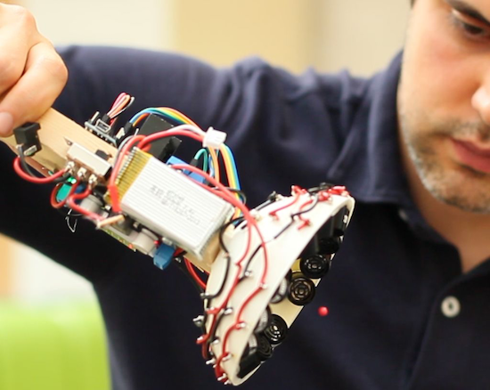
From magic to science, man has long dreamed about being able to manipulate objects from a distance. People have been able to push something using air or even sound waves for a while, but University of Bristol researcher Asier Marzo and colleagues have come up with a 3D-printable device that can not only repel small items, but can also attract them to the source.
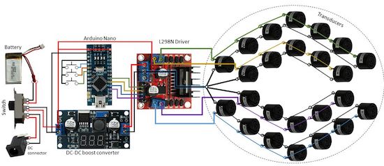
It does this using an array of sound transducers arranged in a dome shape at the end of a wand. The acoustic tractor beam is also equipped with an Arduino Nano, a motor controller board, a DC-DC converter, and a LiPo battery, among some other easily accessible components.
Basically, an Arduino will generate 4 half-square signals at 5Vpp 40kHz with different phases. These signals get amplified to 25Vpp by the motor driver and fed into the transducers. A button pad can be used to change the phases so that the particle moves up and down. A battery (7.3V) powers the Arduino and the logic part of the motor driver. A DC-DC converter steps-up the 7.3V to 25V for the motor driver.
Aside from entertaining friends by levitating small pieces of plastic, the DIY tractor beams have many possible use cases, particularly in biological research. However, there are some limitations. Given the challenge of suspending objects more than half the wavelength of sound, the gadget can only trap things around a few millimeters in size.