Make a Bird Activity Monitor and Feeder with Arduino
 Create a digital bird feeder that can monitor weather and bird activity.
The post Make a Bird Activity Monitor and Feeder with Arduino appeared first on Make: DIY Projects and Ideas for Makers.


Create a digital bird feeder that can monitor weather and bird activity.
The post Make a Bird Activity Monitor and Feeder with Arduino appeared first on Make: DIY Projects and Ideas for Makers.
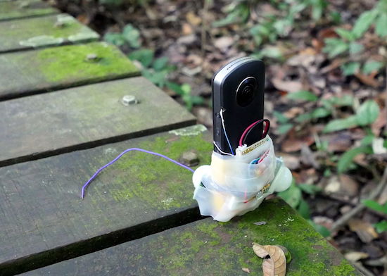
Using an Arduino, wildlife observer and hiking hacker Andrew Quitmeyer modified a spherical camera to take pictures when motion is detected.
If you’d like to photograph wildlife without actually being there to scare the animals off (or because you would eventually get bored), a great solution is a camera trap. These devices can trigger a camera when animals move nearby, hopefully capturing interesting images. Generally, you need to point your camera in the right direction, but Quitmeyer got around this by using a 360 camera instead to eliminate this placement bias.

In order to control the device, he rigged up his own system with PIR motion sensors and an Arduino Uno to prompt the camera as well as power it on and off. The hack looks effective, though voiding an expensive camera’s warranty like this will certainly scare a few Makers off!
You can see more about how this project was pulled off on Instructables, and find the Arduino code used on GitHub.
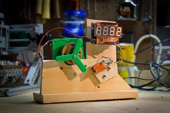
Pete “Raster” Prodoehl shows how to test microswitches with an Arduino Uno.
As referenced in his write-up, Prodoehl needed a way to test microswitches that he’d be using for an exhibit. After all, when something is on display, the last thing you want is to have to replace components. Inspired by how Consumer Reports tests things, he decided to build his own setup with a counter and 3D-printed “pusher.”
What he found was that when you’re testing the life span of a component made to work over and over, your testing components have to also be robust enough to handle the very gradual abuse. It’s an interesting exercise, and something that engineers in manufacturing have to deal with constantly. Getting something to work once or even a times is neat, but getting it to function thousands of times for a test or otherwise takes a different way of thinking!
You can see more about this project on Prodoehl’s page here, and check out the video compilation below for a quick overview.

If you want a light-up dance floor for your next wedding or other special event, you can rent one; however, that can be quite expensive. On the other hand, you and your hacker friends can always build one. How hard can that be?
Turns out, very hard. While it may be simple to get one translucent panel to illuminate with LEDs, this 17-square-foot interactive dance floor used 64 panels with four lighting cells in each, for a total of 256 lighting arrays and 7,680 RGBs arranged as 2,560 addressable pixels.
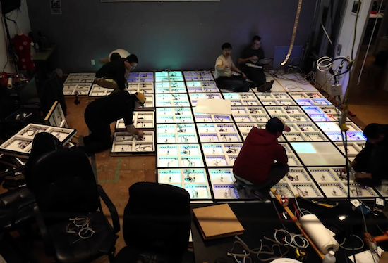
Even with some advanced tools like a pick-and-place machine for PCB manufacturing, as well as a laser cutter, it still took volunteers many hours over the course of 11 months to get it working. LED control is accomplished via a Teensy 3.1, while 256 pressure switches under the surface are read by an Arduino Mega.
You can see more details of the impressive project in the video below (including a round of multi-player Dance Dance Revolution) and a few more technical details in AvBrand’s write-up here.
 If you’re tired of watching normal YouTube videos, why not take it to the Max with MAX Maker? Max’s projects are an eclectic mix of well-made builds, ranging from a motorized camera slider, to a steak knife handle, to a large ruler case. If you do watch his videos, you’ll […]
The post Weekend Watch: Everything from Rock Climbing to Camera Rigs with MAX Maker appeared first on Make: DIY Projects and Ideas for Makers.
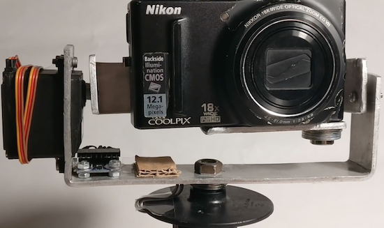
Tadej Strah, a freshman at Gimnazija Vic in Slovenia, made a motorized gimbal using only $60 worth of parts.
After joining a photo and film club at his university, Strah was inspired by a member with cerebral palsy to build an inexpensive gimbal to keep a small camera level. His project uses an MPU-6050 sensor to detect motion, and an Arduino Mega to process this data and control the device’s two servos. The setup includes a handle from an angle grinder, while the servos are mounted on bent pieces of metal, helping keep the cost down.
Strah believes that with a few upgrades, such as a smaller battery, Bluetooth connectivity, and a 3D-printed frame, it should be able to provide many of the features of those available for $500 or more. Hopefully we’ll see this design become even better in the future!
Until then, you can follow along with Strah’s progress, and perhaps another iteration of his gimbal, on his YouTube channel.
 Big parties need a conversation piece, and what’s better than a drink-making robot? Not only is it a good conversation starter, it also frees up the party host who would normally be the bartender. It turned out that the drink robot was a really good idea. The Mai Tai recipe presented here […]
The post Build a Simple Cocktail Drinkbot with Arduino appeared first on Make: DIY Projects and Ideas for Makers.
For Matlab 2013b or earlier
For Matlab 2014a and beyond
After downloading the support package, extract the zip file and paste it in installation directory:
C:/Program Files/Matlab/Bin/ArdunioIO
After pasting, open Matlab. In command window: install_arduino

Upload the adioes program in arduino board

% connect the board
a=arduino('COM5')   % Choose correct com port

pinMode(a,13,'output');  % make pin13 as output
digitalWrite(a,13,0); // make digital pin 13 low (0)
Video for library installation:[agp.cooper]’s son recently went to China, and the biggest complaint was the Great Firewall of China. A VPN is a viable option to get around the Great Firewall of China, but [agp] had a better idea: an acoustic coupler for his son’s iPhone.
 Hackaday readers of a recent vintage might remember an old US Robotics modem that plugged into your computer and phone line, allowing you to access MySpace or Geocities. Yes, if someone picked up the phone, your connection would drop. Those of us with just a little more experience under our belts will remember the acoustic coupler modem — a cradle that held a phone handset that connected your computer (indirectly) to the phone line.
With a little bit of CNC work, [agp] quickly routed out a block of plywood that cradled his son’s iPhone. Add in a speaker and a microphone, and that’s an acoustic coupler. There’s not much to it, really. The real challenge is building a modem.
In the late 90s, there were dedicated chipsets for modems, and before that, there was a 74xx-series chip that was a 300-baud modem. [agp] isn’t using anything like that. He’s building a modem with an Arduino. This is a Bell 103A-compatible modem, allowing an iPhone to talk to a remote computer at 300 bits per second. This is a difficult challenge; we’re not able to get 33kbps over a smartphone voice connection simply because of the codecs used. However, with a little bit of work, [agp] managed to build a real modem with an Arduino.


Clocks that read time via received radio signals have several advantages over their Internet-connected, NTP-synchronised brethren. The radio signal is ubiquitous and available over a fairly large footprint extending to thousands of kilometres from the transmitting antennae. This allows such clocks to work reliably in areas where there is no Internet service. And compared to GPS clocks, their front-end electronics and antenna requirements are much simpler. [Erik de Ruiter]’s DCF77 Analyzer/Clock is synchronised to the German DCF77 radio signal, which is derived from the atomic clocks at PTB headquarters. It features a ton of bells and whistles, while still being simple to build. It’s a slick piece of German hacker engineering that leaves us amazed.
Among the clock functions, it shows time, day of the week, date, CET/CEST modes, leap year indications and week numbers. The last is not part of the DCF77 protocol but is calculated via software. The DCF77 analyzer part has all of the useful information gleaned from the radio signals. There are displays for time period, pulse width, a bit counter, bit value indicator (0/1) and an error counter. There are two rings of 59 LEDs each that provide additional information about the DCF77 signal. A PIR sensor on the front panel helps put the clock in power save mode. Finally, there is a whole bunch of indicator LEDs and a bank of switches to control the various functions. On the rear panel, there are RJ45 sockets for the DCF77 receiver antenna board, temperature sensor and FTDI serial, a bunch of audio sound board controls, reset switches and a mode control switch.
His build starts with the design and layout of the enclosure. The front panel layout had to go through a couple of iterations before he was satisfied with the result. The final version was made from aluminium-coated sandwich-panel. He used an online service to photo-etch the markings, and then a milling machine to carve out the various windows and mounting holes. The rear panel is a tinted acrylic with laser engraving, which makes the neatly laid out innards visible for viewers to appreciate. The wooden frame is made from 40-year-old Mahogany, sourced from an old family heirloom desk. All of this hard work results in a really professional looking product.
The electronics are mostly off the shelf modules, except for the custom built LED driver boards. The heart of the device is an Arduino Mega because of the large number of outputs it provides. There are seven LED driver boards based around the Maxim 7221 (PDF) serial interface LED drivers – two to drive the inner and outer ring LEDs, and the others for the various seven-segment displays. The numerous annunciator LEDs are driven directly from the Arduino Mega. His build really comes together by incorporating a noise resilient DCF77 decoder library by [Udo Klein] which is running on a separate Arduino Uno. All of his design source files are posted on his GitHub repository and he hopes to publish an Instructable soon for those who would like to build one of their own.
In the first video below, he walks through the various functions of the clock, and in the second one, gives us a peek in to its inside. Watch, and be amazed.
Thanks for the tip, [Nick]

