Mini Hacker Breaks Down How To Build It
I read the other day that the hot career choice for kids these days is: YouTuber. That means every kid — yes, including mine — has two or three attempts at a YouTube show on their account and then they get into the next big thing and forget about it. On the other hand, sometimes you find someone who has a lot of ideas to share, and the dedication to keep sharing them.
 [Kevin Zhou], an 11-year-old from Indonesia, has filmed around 70 videos in the past couple of years, with a fantastic variety of nerdy projects ranging from Mindstorms to Arduino to wood shop projects, and even a Blender tutorial. His projects show a lot of complexity, with serious, real-world concepts, and he shares the technical details about the various components in the project, and he walks you through the code as well.
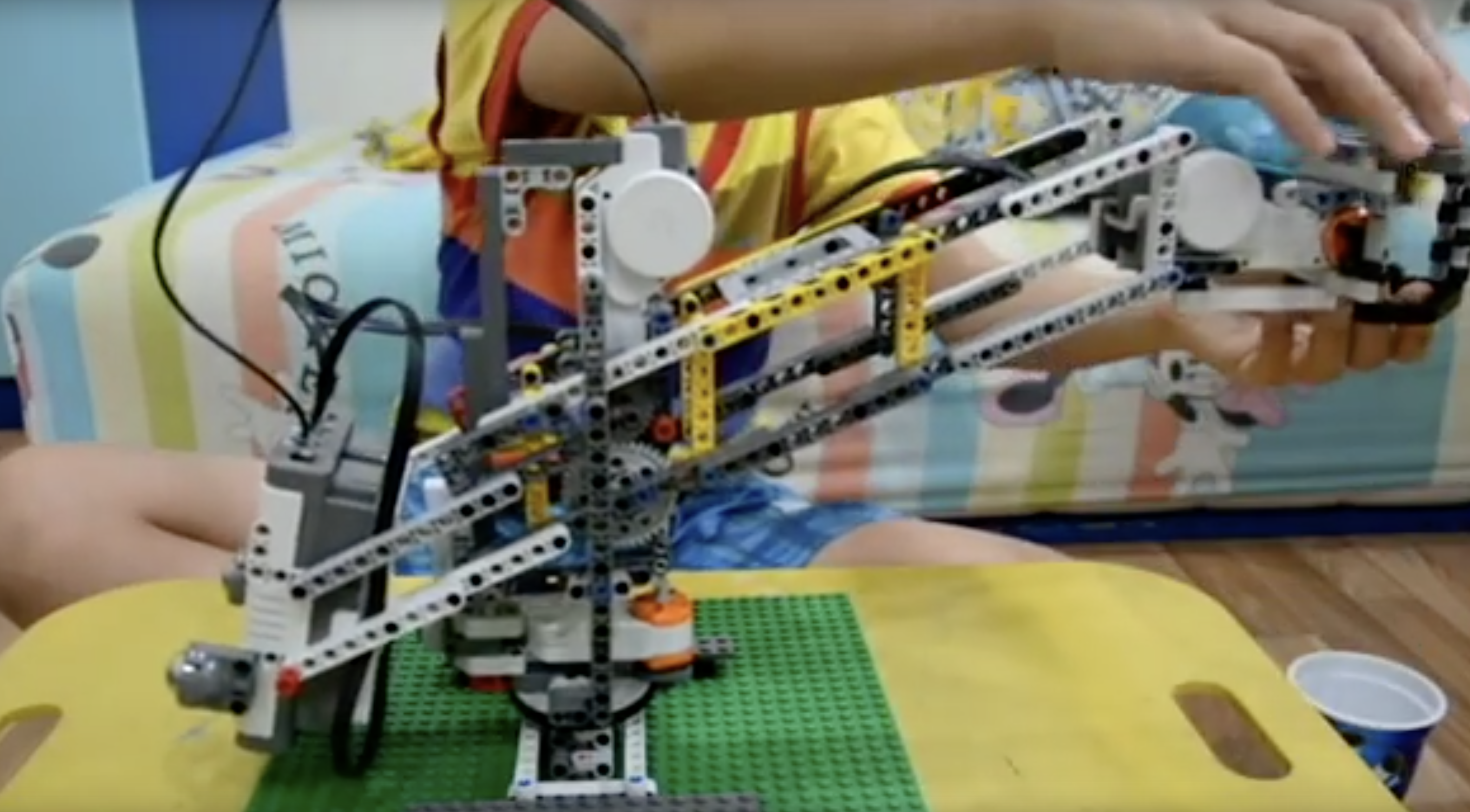
He made a Mindstorms carving machine, pictured above, with a gantry system holding a motor steady while the user carves into a block of floral foam with LEGO bits. He does a lot of home automation projects using an Arduino and relay board, as well as a number of water-pumping robots. He doesn’t stick to one medium or technology. He has a jigsaw and in one video he shows how to build a Thor’s hammer out of wood. He prints out each layer’s design on office paper and glues the paper to a piece of wood, cutting out the cross-sections on his jigsaw. The whole stack is glued together and clamped. [Kevin]’s design featured a hollow space inside to save weight, which he cut by drilling a 1-inch hole in the center with his drill press, then threading the jigsaw blade through the hole to cut out the inside. As an amateur woodcrafter myself, I like seeing him branching out working on small wood projects.
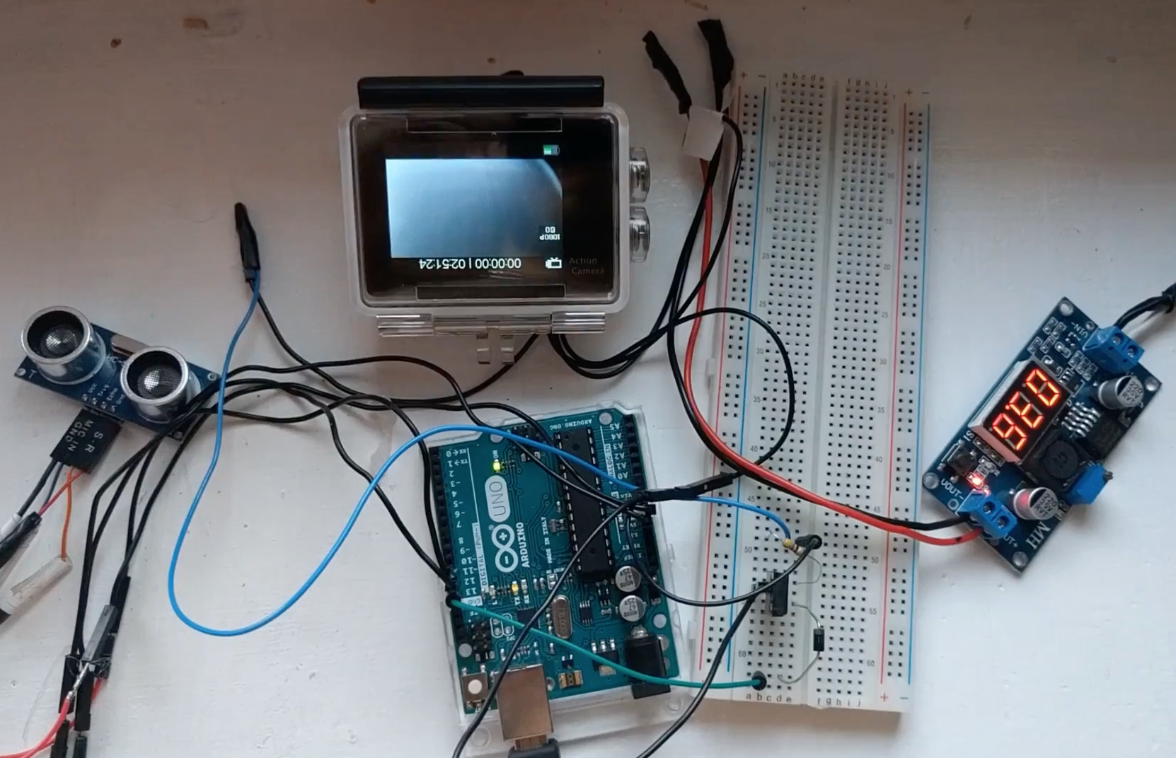
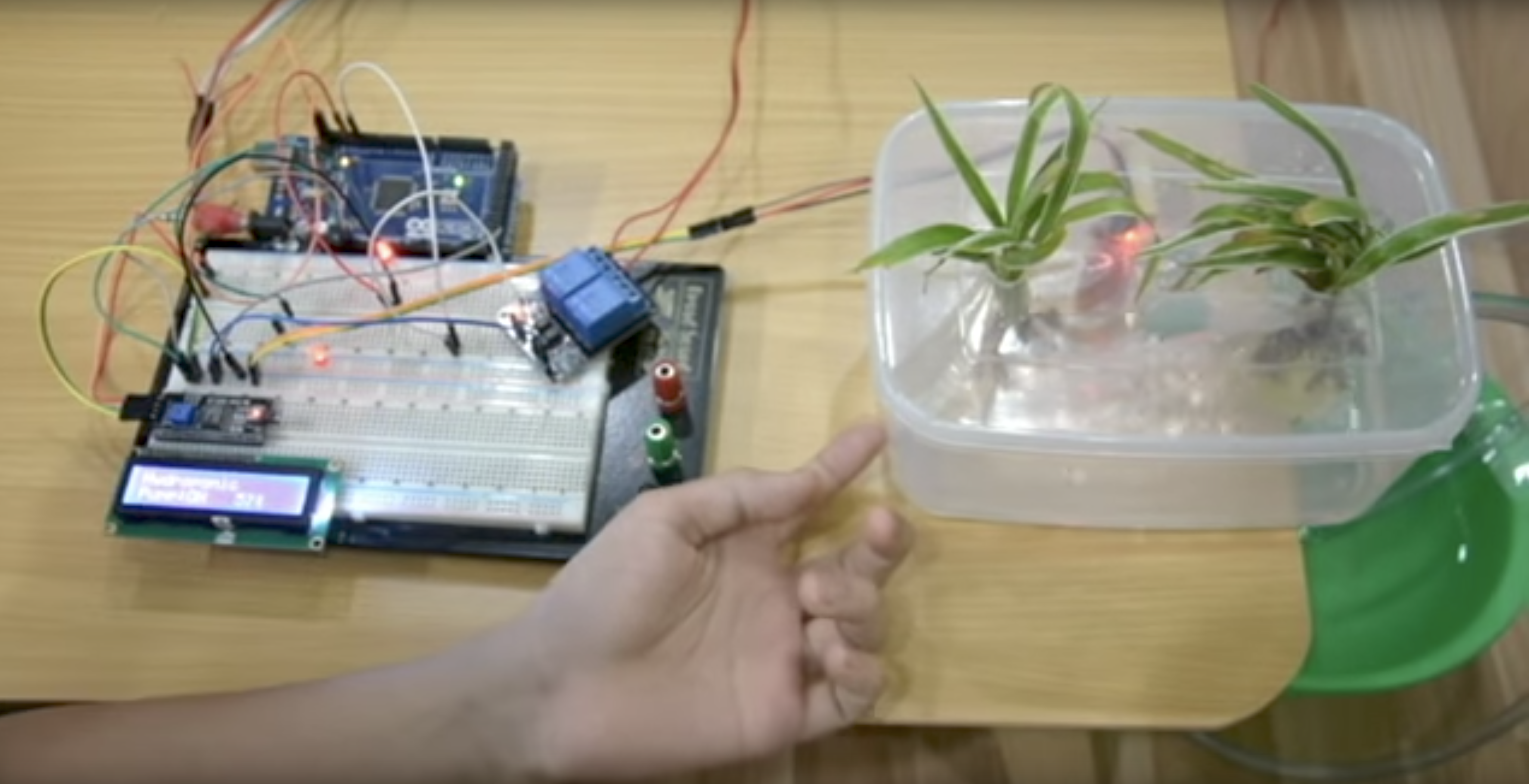 [Kevin]’s full automatic water dispenser is one of a series of water-pumping projects including a couple of plant-watering robots. [Kevin] uses a relay-triggered pump and a water-level sensor, all running on an Arduino Mega plugged into a 1360-point breadboard.
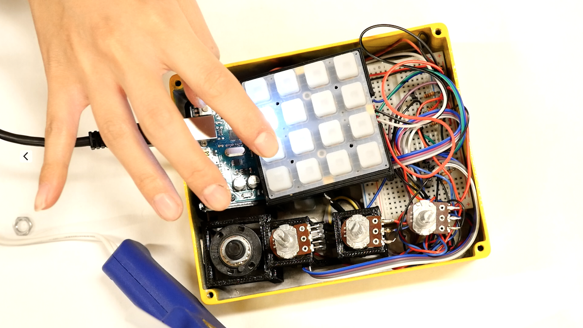
He has a lot of common modules. He uses a LED display plugged directly into the breadboard, with its backpack plugged into same rows so it can lay flat. He plays around with an IR remote, as well as a 12 V / 5 A Peltier thermo-electric cooler running off of a relay. He has a couple of different relay boards making for a number of home automation projects, including a fairly complicated security system featuring RFID and keypad entry.
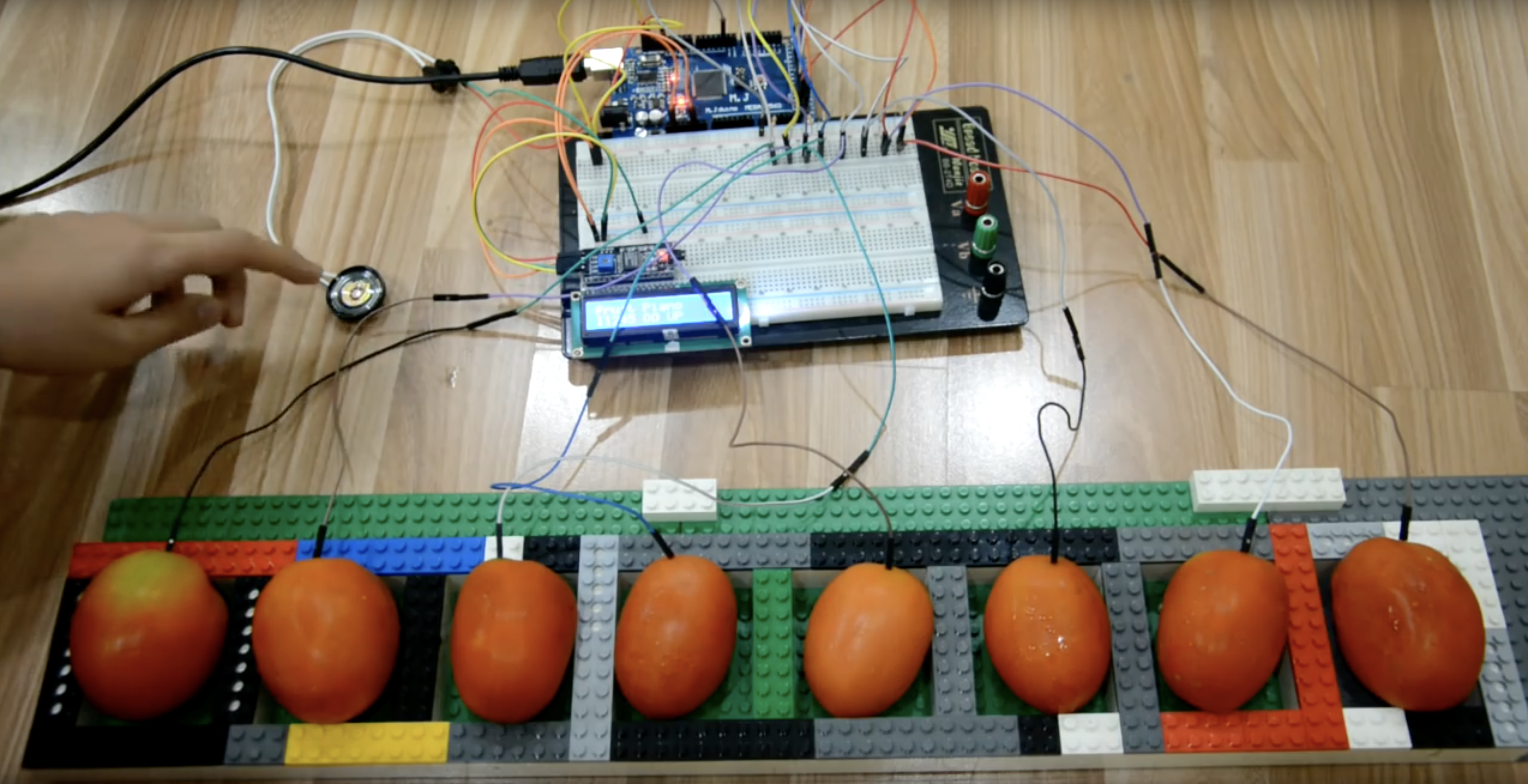
 There are many LEGO and Mindstorms projects as well, including a complicated robot arm controlled by a smartphone app, as well as a Technic beam sorter that rolls the beams down a conveyor so that shorter elements fall through smaller holes, while longer pieces continue on to fall in larger holes down the line. Intriguingly to me, he did a couple of projects involving mixing Arduinos and LEGO/Mindstorms, and frequently uses the building set to build enclosures and support structure.
I suppose you could say the individual projects aren’t that challenging–connecting a relay board to an Arduino, for instance. All of these parts are fairly simple to run individually but together show he’s been working at this for a long time: 70 videos. A DIY security system is a far cry from turning on a LED.
Besides, I like how [Kevin] finishes projects, then riffs off of them. He tries out a few variants in a row, making changes and improvements. I just hope he keeps building–I can’t imagine what he’ll be making fifteen years from now.
Check out some of his videos:
Filed under: Arduino Hacks, Featured