Posts with «arduino nano» label

Display time on a 1950s multimeter

Given an input and some sort of indicator, is there any device that can’t be hacked into a timepiece? With the help of an Arduino Nano and an ESP8266 module, Guilio Pons has created a unique clock out of a 1950s-era multimeter.

Pons’ project not only displays time with an indicator originally meant to reveal electrical values, but is also able to output sounds as needed using a speaker recovered from an old toy. He integrated three LEDs as well as a PIR sensor, so the unit can light up at night.

PWM control from the Arduino takes care of moving the gauge, while the ESP8266 allows the time to be synchronized via the Internet and the alarm adjusted over WiFi.

Want to retrofit a vintage tester of your own? Be sure to check out the Pons’ entire log on Hackaday.io. You can find the software library that he used to play sounds here.

Laptop control box provides speedy access to apps

If you need to quickly launch certain apps on your MacBook Pro, Carl Gordon has your solution using an Arduino Nano.

Although the TV ads for your notebook computer would perhaps have you believe that everyone who uses it is a DJ, artist, or rock climber, chances are you just use it for a handful of programs and folders over and over. If this sounds like you, you can at least speed up access to them using Gordon’s “Laptop Control Box.”

As seen below, the box acts as a grid of shortcuts to your favorite applications, with a button to select sets of programs and an embedded RGB LED module to show you which set is active without having to look at the screen. Control on the computer side is accomplished with Processing, and though it might look like its window needs to be active in the video, it can work in the background as well.

This version currently gives me to access 24 different functions which are divided into six categories of four functions for ease of use, these categories include: tools, media, browser, utilities, social and lifestyle. Categories can be navigated through using the small button on the side and each category is visualized with a unique color by an RGB LED within the device, illuminating the plastic buttons from underneath.

Check out how to make this handy little gadget in Gordon’s Instructables write-up here.

Remotely control a sumo bot with a gaming wheel

Using an Arduino Uno, Nano, and two Bluetooth modules, engineering student “Roboro” can now remotely control his sumo robot.

Like many hackers, Roboro had an old gaming controller that he wasn’t using, in this case an Xbox steering wheel and pedals. Naturally, he converted it into a controller for his sumo robot, which can now be driven manually. This involved wiring the wheel controls into an Uno; the smaller Nano was used onboard the bot.

Rewiring a controller is nothing new, but what is also quite interesting from a hack point of view is that the Arduinos communicate over Bluetooth. When initiated, the controller connects itself to the robot, which can then be driven around (as long as it doesn’t get stuck in the hardwood).

You can see more details of this build on Roboro’s project page.

7 Lessons from Building a GoPro Auto-Panorama Device

Trick your GoPro into taking pictures with a recording

Read more on MAKE

The post 7 Lessons from Building a GoPro Auto-Panorama Device appeared first on Make: DIY Projects and Ideas for Makers.

Giant interactive crossword puzzle uses over 130 Arduino

In what is perhaps the most Arduino boards used together, 130 Arduino Nanos, (plus an Arduino Mega), 130 RFID readers, and 750 RGB LEDs power this interactive crossword puzzle.

As you might suspect, bringing a giant crossword puzzle to life was lot of work. If you’d like to know how much, you can see the process laid out in the video below. Like many great hacks, this project starts out with a lot of prep, making sure the mechanical pieces go together as they should. Everything is then wired and programmed, and on day six, it finally goes out the door, destined for the National Museum in Warsaw, Poland.

Each letter has an RFID tag. Under the table are custom made circuits with Arduino Nano, RFID reader, and WS2812B. There is 130 of those circuits and the are connected by I2C interface together to Arduino Mega 2560, which is the main brain. So basically, the table recognizes letters and takes proper actions.

  • When there is no letter: LED are dimmed white
  • When letter is good: LED are green
  • When letter is bad: LED are red
  • When whole word is completed: LED play colorful animation
The main controller (Arduino Mega) communicates with a PC via RS-232. This PC plays special graphic visualization on the wall. When the whole crossword is completed, the whole table begins doing disco + sound effects.

It’s quite a colorful display, and it looks like the kids playing with it in the “Anything Goes” exhibition love it! You can see more about this project in Robert Mordzon’s write-up.

Huge Interactive Crossword

Give kids some responsible and challenging tasks, and you’d be surprised at the results. The “Anything Goes” exhibit at the National Museum in Warsaw was aimed as a museological and educational experiment. A group of 69 children aged 6–14 was divided into teams responsible for preparing the main temporary exhibition at the museum. Over six months, they worked on preparing the exhibition during weekly four-hour meetings. They prepared scripts, provided ideas for multimedia presentations, and curated almost 300 works for display. One of those was [Robert Mordzon]’s Giant Interactive Crossword.

The build is in two parts. The letter tiles, which have embedded RFID tags, obviously look like the easiest part of the build. The table, looking at the video (after the break), probably needed a lot more effort and labour. It is built in two halves to make construction easier. There are a 130 boxes that need to be filled in with the right letters to complete the crossword. Each box contains a bunch of electronics consisting of an Arduino Nano, a RFID Reader and a bunch of sixteen WS2812B LEDs, all assembled on a custom PCB. Do the math, and you’ll figure out that there’s 2080 LEDs, each capable of sipping 60 mA at full brightness. That’s a total current requirement of almost 125 amps at 5 V. Add in all the Arduino’s, and [Robert] needed a beefy 750 W of power, supplied via four switch mode power supplies.

Each Arduino Nano is a slave on the I²C bus. The I²C master is an Arduino Mega 2560, which in turn communicates with a computer over serial. When a box is empty, the LEDs are dim, when a wrong letter is placed, they turn Red, and when the right letter is placed, they turn Green. If a word gets completed, a special word animation is played. This information is also passed on to the computer, which then projects an animation related to the word on a giant wall screen. Upon the crossword getting completed, the table erupts in to a sound (via the computer) and light “disco” show and also reveals the main motto of this section of the exhibit – “Playing the Hero”.


Filed under: Arduino Hacks

Replace a microwave’s beeping with the Windows XP startup sound

When your microwave is done with its food, it generally beeps… and beeps… and beeps. Though you definitely want to know when your frozen burrito is edible, if you get to it right when it wants, things can get quite annoying. Tim Gremalm decided to do something about it, and replaced the buzzer in his appliance with an Arduino Nano, an amplifier, and small speaker.

His initial speaker/amplifier combination wasn’t loud enough so he replaced it with more appropriate options. After this hack, he now has something that can play a more pleasing tone—in his case, the Windows XP startup sound—and do so only once!

You can see more of this project on Gremalm’s page, as well as check out his code here or this Arduino program that inspired his code. It’s a neat hack, and a great example of what can be done with an Arduino, but you probably shouldn’t mod your microwave unless you really know what you’re doing!

M&Ms and Skittles Sorting Machine is Both Entertainment and Utility

If you have OCD, then the worst thing someone could do is give you a bowl of multi-coloured M&M’s or Skittles — or Gems if you’re in the part of the world where this was written. The candies just won’t taste good until you’ve managed to sort them in to separate coloured heaps. And if you’re a hacker, you’ll obviously build a sorting machine to do the job for you.

Use our search box and you’ll find a long list of coverage describing all manner and kinds of sorting machines. And while all of them do their designated job, 19 year old [Willem Pennings]’s m&m and Skittle Sorting Machine is the bees knees. It’s one of the best builds we’ve seen to date, looking more like a Scandinavian Appliance than a DIY hack. He’s ratcheted up a 100k views on Youtube, 900k views on imgur and almost 2.5k comments on reddit, all within a day of posting the build details on his blog.

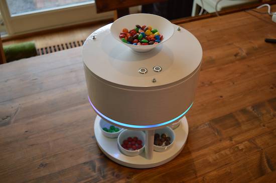
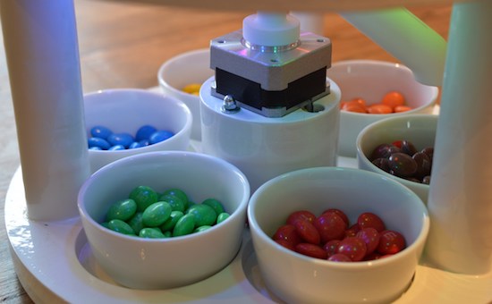
As quite often happens, his work is based on an earlier design, but he ends up adding lots of improvements to his version. It’s got a hopper at the top for loading either m&m’s or Skittles and six bowls at the bottom to receive the color sorted candies. The user interface is just two buttons — one to select between the two candy types and another to start the sorting. The hardware is all 3D printed and laser cut. But he’s put in extra effort to clean the laser cut pieces and paint them white to give it that neat, appliance look. The white, 3D printed parts add to the appeal.

Rotating the input funnel to prevent the candies from clogging the feed pipes is an ace idea. A WS2812 LED is placed above each bowl, lighting up the bowl where the next candy will be ejected and at the same time, a WS2812 strip around the periphery of the main body lights up with the color of the detected candy, making it a treat, literally, to watch this thing in action. His blog post has more details about the build, and the video after the break shows the awesome machine in action.

And if you’re interested in checking out how this sorter compares with some of the others, check out these builds — Skittles sorting machine sorts Skittles and keeps the band happy, Anti-Entropy Machine Satiates M&M OCD, Only Eat Red Skittles? We’ve Got You Covered, and Hate Blue M&M’s? Sort Them Using the Power of an iPhone!  As we mentioned earlier, candy sorting machines are top priority for hackers.

[via r/electronics]


Filed under: Arduino Hacks, cooking hacks

Sort your M&Ms or Skittles with this ingenious machine

Inspired by a YouTube video of another candy sorter, Willem Pennings decided to build his own version.

After nearly eight months of work, he now has a device that can separate M&Ms or Skittles into their respective color dishes. Control is accomplished via a pair of Arduino Nano boards along with two EasyDrivers and an RGB sensor. These actuate a small servo for mixing the candies, and a stepper motor to properly position the candy tube.

Besides designing the controls for the machine, everything is modeled beautifully in the NX10 CAD package. The results, as seen in the video, look extremely polished–and it’s quite soothing to watch these candies drop into their little bowls in automated fashion!

You can find more details on Pennings’ project page and check out the video that inspired him here.

Make your own 3D-printed sonic tractor beam with Arduino

From magic to science, man has long dreamed about being able to manipulate objects from a distance. People have been able to push something using air or even sound waves for a while, but University of Bristol researcher Asier Marzo and colleagues have come up with a 3D-printable device that can not only repel small items, but can also attract them to the source.

It does this using an array of sound transducers arranged in a dome shape at the end of a wand. The acoustic tractor beam is also equipped with an Arduino Nano, a motor controller board, a DC-DC converter, and a LiPo battery, among some other easily accessible components.

Basically, an Arduino will generate 4 half-square signals at 5Vpp 40kHz with different phases. These signals get amplified to 25Vpp by the motor driver and fed into the transducers. A button pad can be used to change the phases so that the particle moves up and down. A battery (7.3V) powers the Arduino and the logic part of the motor driver. A DC-DC converter steps-up the 7.3V to 25V for the motor driver.

Aside from entertaining friends by levitating small pieces of plastic, the DIY tractor beams have many possible use cases, particularly in biological research. However, there are some limitations. Given the challenge of suspending objects more than half the wavelength of sound, the gadget can only trap things around a few millimeters in size.

Marzo and his team have published their project in the journal Applied Physics Lettersand shared step-by-step instructions so you could get started on building your own beam. You can read more on Phys.org as well.