Posts with «arduino nano» label

A Paris-inspired, Arduino-powered binary clock

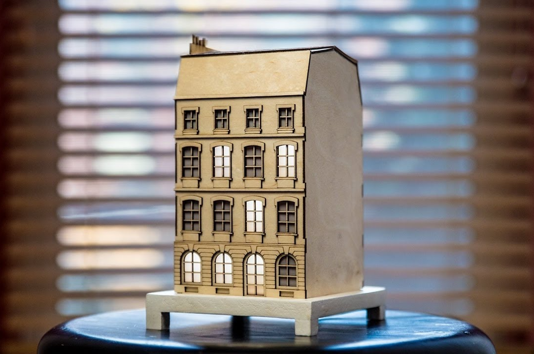
The La Fabrique DIY team has been working on a unique clock modeled after buildings seen along the Seine River in Paris. The “City Clock” is different from the others in that instead of a dial or decimal numbers, windows light up in a binary format, displaying the time in a binary sequence.

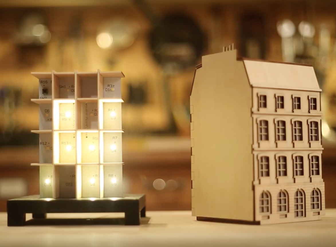
Electronics-wise, the clock can be made with an Arduino Uno, involving a fairly simple circuit with individual LEDs and resistors, as seen on this Imgur set. Also shown there is the Kickstarter version of the circuit, which amounts to a sort of gigantic shield that an Arduino Nano is plugged into.

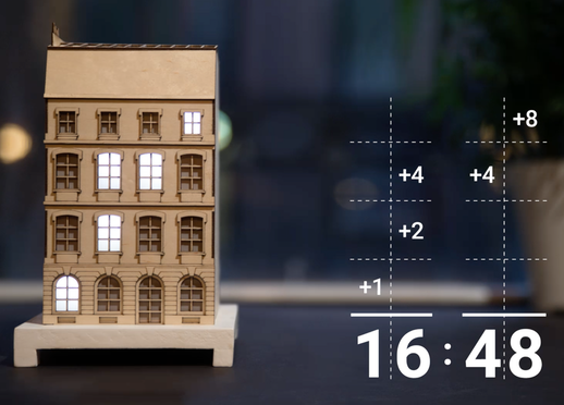
With the City Clock, you calculate the time by adding every digit vertically. The first floor equals one, second equals two, third equals four, and the top equals eight. Using this system, it’s possible to create every digit from zero to nine by adding one number to another.

These clocks are available in various kit forms, including just the electronics or frame if you’d like a head start crafting something truly your own!

Computer gesture control via webcam and Arduino

While touchscreens are nice, wouldn’t it be even better if you could simply wave your hand to your computer to get it to do what you want? That’s the idea behind this Iron Man-inspired gesture control device by B. Aswinth Raj.

The DIY system uses an Arduino Nano mounted to a disposable glove, along with hall effect sensors, a magnet attached to the thumb, and a Bluetooth module. This smart glove uses the finger-mounted sensors as left and right mouse buttons, and has a blue circle in the middle of the palm that the computer can track via a webcam and a Processing sketch to generate a cursor position.

You can see it demonstrated in the video below, drawing a stick man literally by hand, and also controlling an LED on the Nano. Check out this write-up for code and more info on the build!

Arduino Blog 31 May 21:41

Turn your door into an ‘alien portal’ using Arduino

As YouTuber Evan Kale puts it, his set is was kind of boring. He decided to spruce things up by turning his ordinary door into an “alien portal,” lining it with a strip of RGB LEDs. Though this may not be the first time you’ve seen this type of lighting in action, he directs our attention to a few interesting details about using them in typical Kale style.

One interesting note comes around the 4:50 mark, where he points out his portal is controlled using Hue Saturation Lightness (HSL) via a potentiometer instead of RGB. This keeps the glowing effect consistent, while allowing color adjustment.

For this project, he employed an Arduino Nano, which looks like a great choice since it needs a limited amount of I/O. Using this tiny board, the entire control package can fit into his small 3D-printed enclosure.

You can see a demo of Kale’s “alien portal” below, and check out his channel for more fun Arduino projects!

Arduino Blog 15 May 20:01

Enhance your keyboard with the SlideBar

Using a keyboard and mouse usually gets the job done, but if you want to navigate around a website or video, the process could be a little more efficient. It may not be a big deal to reach over and use your mouse and scroll wheel, but if you had this control on your keyboard, that tiny bit of time savings could add up over the thousands of times you do this.

For this purpose, Imgur user “Electricrelay” added a motorized force feedback slider to his keyboard using an Arduino Nano for control. This easily customizable device can scroll through pages, or switch between open browser tabs or programs. It can also act as a mechanical display, shaking for notifications, or sliding with keystrokes like an old-school typewriter. The Maker even created a plugin for timeline scrubbing in Adobe Premiere.

Check out lots of example animations on the project’s Imgur page here and see it in action below!

DIY panoramic thermal imaging

Using an Arduino Nano and two rotary stages, this Maker hacked together a panoramic thermal imaging camera.

After ordering and finally receiving a thermopile (infrared thermometer) in the mail, the author of this project set to work to construct his own scanning thermometer. This type of setup acts like an IR camera, but instead of taking one instantaneous picture, it stores thermal data points that are then resolved into a coherent image.

Though the panoramic results can be fantastic, since the thermometer has to be rotated to each point individually via stepper motors on the rotary stages, a single image capture can take over an hour.

You can find more details of the build here.

These e-tattoos turn your skin into smartphone controls

Electronic interfaces have advanced from plugging things in, to keyboards, touchscreens, VR environments, and perhaps soon temporary tattoos. Led by Martin Weigel, researchers at Saarland University in Saarbrücken, Germany have come up with a way to turn your skin blemishes and wrinkles into touch-sensitive controls for devices like smartphones and computers.

“SkinMarks” can be transferred onto the skin using water and last a couple of days before rubbing off. As seen in the video below, these e-tattoos can take the form of buttons, sliders and visual displays, and even sense when a joint is bent. For example, knuckles on a hand made into a fist could act as buttons and then become a slider when the fingers are straightened.

Another type of SkinMark is electroluminescent, meaning that an image printed on your skin could light up to signal a phone call or other important notifications. These tattoos are connected to a wrist-mounted Arduino Nano and an Adafruit MPR121 capacitive touch shield via wires and copper tape; though if the system can be shrunk down even further, this could open up many different possibilities!

You can find more information on this project on New Scientist, or in the team’s published paper here.

Add flair to your turn signals with programmable LEDs

Modding vehicles to do something different and unique has been a pastime of “motorheads” almost since cars began to replace horses. Many modifications involve speed, but some like these fancy turn signals by Shravan Lal, simply supplement the looks of his ride.

An Arduino Nano was used as the brains of this hack in order to control strips of WS2812B LEDs acting as blinkers (similar to those on the new Audi A6) in the video below. In addition to signaling a right or left turn, Lal’s build also has a neat startup animation, and can act as a set of hazard lights if needed.

It’s a neat project, with lots of further potential; on the other hand, be sure to check the legality of this type of modification in your area before attempting something similar! You can find more information on his GitHub page. Speaking of customizing cars, don’t miss AtHeart’s Macchina M2 on Kickstarter now!

Prextron CHAIN BLOCKS - Arduino Nano controlled Ultrasonic sensor that switches a motor wirelessly using 433MHz RF modules and a relay board.


Description

In this tutorial, I will be evaluating Prextron CHAIN blocks – a new system that allows you to connect your sensors and actuators to an Arduino NANO using clever 3D-printed prototyping boards that can be stacked sideways. This very modular system makes it easy to connect, disconnect and replace project components, and eliminate the “rats nest of wires” common to many advanced Arduino projects. CHAIN BLOCKS are open, which means that you can incorporate any of your sensors or actuators to these prototyping boards, and you can decide which specific pin on Arduino you plan to use. The CHAIN BLOCK connections prevent or reduce common connection mistakes, which make them ideal for class-room projects and learning activities.

I am going to set up a project to put these CHAIN BLOCKs to the test:
When I place my hand in-front of an Ultrasonic sensor, the Arduino will transmit a signal wirelessly to another Arduino, and consequently turn on a motor.


Parts Required:

You need the following Prextron Chain Blocks


Please note: You may need to solder the module wires to the CHAIN BLOCK protoboard.


Arduino Libraries and IDE

This project does not use any libraries. However, you will need to upload Arduino code to the Arduino. For this you will need the Arduino IDE which can be obtained from the official Arduino website:
https://www.arduino.cc/en/main/software


ARDUINO CODE: RF Transmitter


ARDUINO CODE: RF Receiver


Fritzing diagrams for Transmitter


Fritzing diagrams for Receiver


Concluding comments

The purpose of this project was to evaluate Prextron CHAIN BLOCKs and put them to the test. Here is what I thought of CHAIN BLOCKS at the time of evaluation. Some of my points mentioned below may no longer apply to the current product. It may have evolved / improved since then. So please take that into consideration


What I liked about Chain Blocks

  • The design is simple, the product is simple.
  • Once the Chain Blocks were all assembled, they were very easy to connect to each other.
  • I can really see the benefit of Chain Blocks in a teaching environment, because it simplifies the connection process, and reduces connection mixups.
  • It was good to see that the blocks come in different colours, which means that you can set up different colour schemes for different types of modules.
  • You can incorporate pretty much any sensor or Actuator into the Chain block which is very appealing.
  • You also have the flexibility of choosing which pins you plan to use on the Arduino.
  • Projects look a lot neater, because you no longer have the rats nest of wires.
  • The Blocks lock into each other which means that they are much easier to transport/carry.


What I did not like about Chain Blocks

  • In most cases, the Chain Block protoboard lanes were not numbered, which increased the chances of making mistakes when soldering
  • The need to solder modules to the protoboard, may be a discouragement for some people.
  • I would have liked a choice of different size Chain blocks. Some of the sensors did not fit nicely into the Square blocks.
  • Prextron really need to work on their website if they plan to get serious with this product: Webpage has incomplete functionality or irrelevant links etc etc.


Thank you very much to Prextron for providing the CHAIN BLOCKS used in this tutorial, and allowing me to try out their product. If you are interested in trying them yourself, then make sure to visit them at:


If you like this page, please do me a favour and show your appreciation :

 
Visit my ArduinoBasics Google + page.
Follow me on Twitter by looking for ScottC @ArduinoBasics.
I can also be found on Pinterest and Instagram.
Have a look at my videos on my YouTube channel.


Make an “analog” bike speedometer with Arduino

As Maker Alex Gyver points out in his video, Chinese bike computers are quite cheap, but “why not?” It’s a great question, and one that motivates many of the hacks seen here, including his mountain bike speedometer.

Although he could have simply used a numerical display to show how fast his bike was going, he instead employed a small servo to point to the speed like an analog gauge. The custom speedometer is based on an Arduino Nano, and wheel revolutions are measured by a magnetic and Hall effect sensor.

This may seem like a silly project, but if you need to take a very short glance at something, analog gauges tend to be much easier to read than digital. Perhaps this concept could be quite useful! You can see exactly how to make this hack on Instructables and in his video here with a few action shots. Code can be found on GitHub if you’d like to check that out as well!