Tarot Machine Flips Through Fate’s Rolodex
Were tarot card readers deemed non-essential in your part of the world (and do you think they saw it coming?) More than ever, we all need diversions that are for entertainment purposes only. And what better basis for entertainment than a mystical fortune-telling robot that can read your tarot cards?
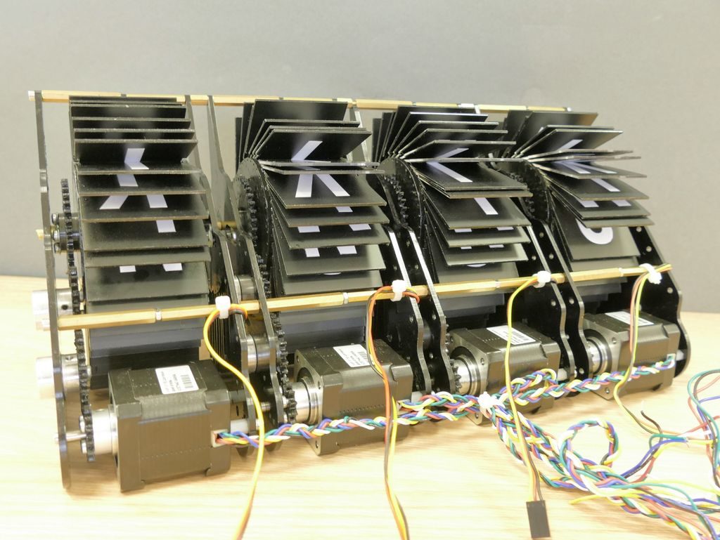
This fantastic-looking ‘bot stands on the shoulders of [Scott Bezak]’s trailblazing method for easy DIY split-flap displays. Push the rather inviting-looking button on the top, and the flaps start flipping around to find your fortune. Once the fates have aligned, a thermal printer on the front spits out an image of your card along with an interpretation.
It’s obvious that [i_mozy] put quite a lot of effort into this slick machine, and we think the stickers look especially great. All the details of physical tarot card readings are accounted for, including a random number to decide the card’s position, and LEDs to represent the card’s element. Suspend your disbelief and check out the demo/promo video after the break.
Split-flap displays are a great choice no matter what you want to show. We’ve seen them used to display everything from the weather to the current Spotify track.
Via r/duino