

The Smallest ATtiny85 Based USB Board

“Possibly the smallest ATtiny85 based ‘duino derivative”. Indeed! When Olimex announced the Olimexino 85s as the smallest Arduino ever, [Tim] took that as a challenge. His very small Arduino based USB devboard is quite a bit smaller than the Olimexino!
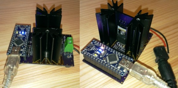
The Nanite 85 was carefully designed to be both small and functional. Not only is it 20% smaller than the Olimexino, but also sports a reset button! One of the coolest aspects of this design is that it has the same pinout and size as a DIP ATtiny85. This means that you can use the Nanite 85 for developing your code with the USB bootloader, and then you can directly replace it with a standard (pre-programmed) ATtiny85. The major downside to using this device over the aforementioned devices, is that it does not include a voltage regulator for powering the device via USB (or battery), the device is simply hooked directly to the 5V rail from the USB connector.
We can’t help but be impressed with this well-thought-out design. It is also easy to assemble since it uses larger surface mount components. If smaller components were used, even more features (such as a regulator) could be included. Do you have an even smaller USB Arduino? The race is on for the smallest Arduino ever!
Filed under: Arduino Hacks


