

The Case for Arduino in “Real Engineering”
For over ten years, Arduino has held onto its popularity as “that small dev-board aimed to get both artists and electronics enthusiasts excited about physical computing.” Along the way, it’s found a corner in college courses, one-off burning man rigs, and countless projects that have landed here. Without a doubt, the Arduino has a cushy home among hobbyists, but it also lives elsewhere. Arduino lives in engineering design labs as consumer products move from feature iterations into user testing. It’s in the chem labs when scientists need to get some sensor data into their pc in a pinch. Despite the frowns we’ll see when someone blinks an LED with an Arduino and puts it into a project box, Arduino is here to stay. I thought I’d dig a little bit deeper into why both artists and engineers keep revisiting this board so much.
Arduino, do we actually love to hate it?
 It’s not unusual for the seasoned engineers to cast some glares towards the latest Arduino-based cat-feeding Kickstarter, shamelessly hiding the actual Arduino board inside that 3D-printed enclosure. Hasty? Sure. Crude, or unpolished? Certainly. Worth selling? Well, that depends on the standards of the consumer. Nevertheless, those exact same critical engineers might also be kicking around ideas for their next Burning Man Persistence-of-Vision LED display–and guess what? It’s got an Arduino for brains! What may seem like hypocrisy is actually perfectly reasonable. In both cases, each designer is using Arduino for what it does best: abstracting away the gritty details so that designs can happen quickly. How? The magic (or not) of hardware abstraction.
Meet HAL, the Hardware-Abstraction Layer
In a world where “we just want to get things blinking,” Arduino has a few nifty out-of-the-box features that get us up-and-running quickly. Sure, development tools are cross-platform. Sure, programming happens over a convenient usb interface. None of these features, however, can rival Arduino’s greatest strength, the Hardware Abstraction Layer (HAL).
A HAL is nothing new in the embedded world, but simply having one can make a world of difference, one that can enable both the artist and the embedded engineer to achieve the same end goal of both quickly and programmatically interacting with the physical world through a microcontroller. In Arduino, the HAL is nothing more than the collection of classes and function calls that overlay on top of the C++ programming language and, in a sense, “turn it into the Arduino programming language” (I know, there is no Arduino Language). If you’re curious as to how these functions are implemented, take a peek at the AVR directory in Arduino’s source code.
With a hardware abstraction layer, we don’t need to know the details about how our program’s function calls translate to various peripherals available on the Uno’s ATMEGA328p chip. We don’t need to know how data was received when Serial.available() is true. We don’t “need to know” if Wire.begin() is using 7-bit addressing or 10-bit addressing for slave devices. The copious amounts of setup needed to make these high-level calls possible is already taken care of for us through the HAL. The result? We save time reading the chip’s datasheet, writing helper functions to enable chip features, and learning about unique characteristics and quirks of our microcontroller if we’re just trying to perform some simple interaction with the physical world.
Cross-Platform Compatibility
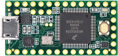
There are some cases where the HAL starts to break down. Maybe the microcontroller doesn’t have the necessary hardware to simultaneously drive 16 servos while polling a serial port and decoding serial data. In some cases, we can solve this issue by switching Arduino platforms. Maybe we actually do need three serial ports instead of one (Teensy 3.2). Maybe we do need pulse-width-modulation (PWM) capability on every pin (Due). Because of the hardware abstraction layer, the rest of the source code can remain mostly unchanged although we may be switching chip architectures and even compilers in the process! Of course, in an environment where developing code for the target platform does matter, it doesn’t make sense to go to such efforts to write the general-purpose code that we see in Arduino, or even use Arduino in the first place if it doesn’t have the necessary features needed for the target end-goal. Nevertheless, for producing an end-to-end solution where “the outcome matters but the road to getting there does not,” writing Arduino code saves time if the target hardware needs to change before getting to that end goal.
HAL’s drawbacks
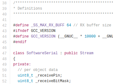 Of course, there’s also a price to pay for such nice things like speedy development-time using the HAL, and sometimes switching platforms won’t fix the problem. First off, reading the Arduino programming language documentation doesn’t tell us anything about the limitations of the hardware it’s running on. What happens, let’s say, if the Serial data keeps arriving but we don’t read it with Serial.read() until hundreds of bytes have been sent across? What happens if we do need to talk to an I2C device that mandates 10-bit addressing? Without reading the original source code, we don’t know the answers to these questions. Second, if we choose to use the functions given to us through the HAL, we’re limited by their implementation, that is, of course, unless we want to change the source code of the core libraries. It turns out that the Serial class implements a 64-byte ring buffer to hold onto the most recently received serial data. Is 64 bytes big enough for our application? Unless we change the core library source code, we’ll have to use their implementation.
Both of the limitations above involve understanding how the original HAL works and than changing it by changing the Arduino core library source code. Despite that freedom, most people don’t customize it! This odd fact is a testament to how well the core libraries were written to suit the needs of their target audience (artists) and, hence, Arduino garnered a large audience of users.
Pros of Bare-Metalspeak
Use the HAL, Luke!
To achieve an end-to-end solution where the process of “how we got there” matters not, Arduino shines for many simple scenarios. Keep in mind that while the HAL keeps us from knowing too many details about our microcontroller that we’d otherwise find in the datasheet, I don’t proclaim that everyone throw out their datasheets from here on out. I am, however, a proponent of “knowing no more than you need to know to get the job done well.” If I’m trying to log some sensor data to a PC, and I discover I’ll be saving a few days reading a datasheet and configuring an SPI port because someone already wrote SPI.begin(), I’ll take an Arduino, please.
If you’ve rolled up your sleeves and pulled out an Arduino as your first option at work, we’d love to hear what uses you’ve come up with beyond the occasional side-project. Let us know in the comments below.
Filed under: Arduino Hacks, Hackaday Columns, tool hacks


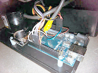 Behind the clock is an Arduino driving a MAX7219 LED controller. Using the MAX7219 was a challenge because it expects a grid of LEDs while the clock needs a linear array. [Dylan] used a line of individual LEDs wired to match what the controller wanted. A rotary encoder tells the processor the position of the arm so the Arduino sketch can determine which LEDs should be lit to show the time and clock face.


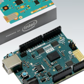 The Arduino/Genuino 101 is the first development platform for the Intel Curie modules which are a recent development from Intel’s Maker and Innovator group. The button-sized Curie is a single package encapsulating microcontroller, Bluetooth, a 6-DOF IMU, and battery charging circuitry; the requisite hardware for anything marketed as a ‘wearable’. The Curie’s brain is a 32-bit Intel Quark microcontroller with 384kB of Flash 80kB SRAM, giving it about the same storage and RAM as a low-end ARM Cortex microcontroller.
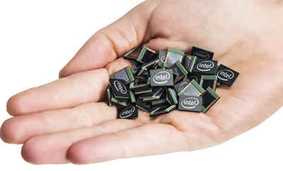 The Arduino 101 and Genuino 101 – different names for the same thing and the first great expression of arduino.cc’s troubles with trademarks and the


