Posts with «arduino hacks» label

PlatformIO and Visual Studio Take over the World

In a recent post, I talked about using the “Blue Pill” STM32 module with the Arduino IDE. I’m not a big fan of the Arduino IDE, but I will admit it is simple to use which makes it good for simple things.

I’m not a big fan of integrated development environments (IDE), in general. I’ve used plenty of them, especially when they are tightly tied to the tool I’m trying to use at the time. But when I’m not doing anything special, I tend to just write my code in emacs. Thinking about it, I suppose I really don’t mind an IDE if it has tools that actually help me. But if it is just a text editor and launches a few commands, I can do that from emacs or another editor of my choice. The chances that your favorite IDE is going to have as much editing capability and customization as emacs are close to zero. Even if you don’t like emacs, why learn another editor if there isn’t a clear benefit in doing so?

There are ways, of course, to use other tools with the Arduino and other frameworks and I decided to start looking at them. After all, how hard can it be to build Arduino code? If you want to jump straight to the punch line, you can check out the video, below.

Turns Out…

It turns out, the Arduino IDE does a lot more than providing a bare-bones editor and launching a few command line tools. It also manages a very convoluted build process. The build process joins a lot of your files together, adds headers based on what it thinks you are doing, and generally compiles one big file, unless you’ve expressly included .cpp or .c files in your build.

That means just copying your normal Arduino code (I hate to say sketch) doesn’t give you anything you can build with a normal compiler. While there are plenty of makefile-based solutions, there’s also a tool called PlatformIO that purports to be a general-purpose solution for building on lots of embedded platforms, including Arduino.

About PlatformIO

Although PlatformIO claims to be an IDE, it really is a plugin for the open source Atom editor. However, it also has plugins for a lot of other IDEs. Interestingly enough, it even supports emacs. I know not everyone appreciates emacs, so I decided to investigate some of the other options. I’m not talking about VIM, either.

I wound up experimenting with two IDEs: Atom and Microsoft Visual Studio Code. Since PlatformIO has their 2.0 version in preview, I decided to try it. You might be surprised that I’m using Microsoft’s Code tool. Surprisingly, it runs on Linux and supports many things through plugins, including an Arduino module and, of course, PlatformIO. It is even available as source under an MIT license. The two editors actually look a lot alike, as you can see.

PlatformIO supports a staggering number of boards ranging from Arduino to ESP82666 to mBed boards to Raspberry Pi. It also supports different frameworks and IDEs. If you are like me and just like to be at the command line, you can use PlatformIO Core which is command line-driven.

In fact, that’s one of the things you first notice about PlatformIO is that it can’t decide if it is a GUI tool or a command line tool. I suspect some of that is in the IDE choice, too. For example, with Code, you have to run the projection initialization tool in a shell prompt. Granted, you can open a shell inside Code, but it is still a command line. Even on the PlatformIO IDE (actually, Atom), changing the Blue Pill framework from Arduino to mBed requires opening an INI file and changing it. Setting the upload path for an FRDM-KL46 required the same sort of change.

Is it Easy?

Don’t get me wrong. I personally don’t mind editing a file or issuing a command from a prompt. However, it seems like this kind of tool will mostly appeal to someone who does. I like that the command line tools exist. But it does make it seem odd when some changes are done in a GUI and some are done from the command line.

That’s fixable, of course. However, I do have another complaint that I feel bad for voicing because I don’t have a better solution. PlatformIO does too much. In theory, that’s the strength of it. I can write my code and not care how the mBed libraries or written or the Arduino tools munge my source code. I don’t even have to set up a tool chain because PlatformIO downloads everything I need the first time I use it.

When that works it is really great. The problem is when it doesn’t. For example, on the older version of PlatformIO, I had trouble getting the mBed libraries to build for a different target. I dug around and found the issue but it wasn’t easy. Had I built the toolchain and been in control of the process, I would have known better how to troubleshoot.

In the end, too, you will have to troubleshoot. PlatformIO aims at moving targets. Every time the Arduino IDE or the mBed frameworks or anything else changes, there is a good chance it will break something. When it does, you are going to have to work to fix it until the developers fix it for you. If you can do that, it is a cost in time. But I suspect the people who will be most interested in PlatformIO will be least able to fix it when it breaks.

Bottom Line

If you want to experiment with a different way of building programs — and more importantly, a single way to create and build — you should give PlatformIO a spin. When it works, it works well. Here are a few links to get you started:

Bottom line, when it works, it works great. When it doesn’t it is painful. Should you use it? It is handy, there’s no doubt about that. The integration with Code is pretty minimal. The Atom integration — while not perfect — is much more seamless. However, if you learn to use the command line tools, it almost doesn’t matter. Use whatever editor you like, and I do like that. If you do use it, just hope it doesn’t break and maybe have a backup plan if it does.


Filed under: Arduino Hacks, ARM, Hackaday Columns, reviews, Skills

Hackaday Prize Entry: [Nardax] Shoots Fireballs

If you’re looking for a high entertainment value per byte of code, [Nardax] has you covered with his wearable spellcasting controller. With not much effort, he has built a very fun looking device, proving what we’ve always known: a little interaction can go a long way.

[Nardax] originally intended his glorified elbow-mount potentiometer to be a fireworks controller. Ironically, he’s now using it to throw virtual fireballs instead. Depending on the angle at which he holds his elbow before releasing it, he can cast different spells in the game World of Warcraft. We’re not at all sure that it helps his gameplay, but we’re absolutely sure that it’s more fun that simply mashing different keys.

There’s a lot of room for expansion here, but the question is how far you push it. Sometimes the simplest ideas are the best. It looks like [Nardax] is enjoying his product-testing research, though, so we’ll keep our eyes out for the next iterations of this project.

We’ve seen a number of high-tech competitors to the good old power glove, and although some are a lot more sophisticated than a potentiometer strapped to the elbow, this project made us smile. Sometimes, it’s not just how much tech you’ve got, but how you use it. After all, a DDS pad is just a collection of switches under a rug.


Filed under: Arduino Hacks, The Hackaday Prize

The $2 32-Bit Arduino (with Debugging)

I have a bit of a love/hate relationship with the Arduino. But if I had two serious gripes about the original offering it was the 8-bit CPU and the lack of proper debugging support. Now there’s plenty of 32-bit support in the Arduino IDE, so that takes care of the first big issue. Taking care of having a real debugger, though, is a bit trickier. I recently set out to use one of the cheap “blue pill” STM32 ARM boards. These are available for just a few bucks from the usual Chinese sources. I picked mine up for about $6 because I wanted it in a week instead of a month. That’s still pretty inexpensive. The chip has a lot of great debugging features. Can we unlock them? You can, if you have the right approach.

The Part

For a few bucks, you can’t complain about the hardware. The STM32F103C8T6 onboard is a Cortex-M3 processor that runs at 72 MHz. There’s 64K of flash and 20K of RAM. There’s a mini-USB that can act as a programming port (but not at first). There’s also many 5 V-tolerant pins, even though this a 3.3 V part.

You can find a lot more information on this wiki. The board is a clone–more or less–of a Maple Mini. In fact, that’s one way you can use these. You can use the serial or ST-Link port to program the Maple bootloader (all open source) and use it like a Maple. That is, you can program it via the USB cable.

From my point of view, though, I don’t want to try to debugging over the serial port and if I have the ST-Link port already set up, I don’t care about a bootloader. You can get hardware that acts as a USB to ST-Link device inexpensively, but I happen to have an STM32VLDISCOVER board hanging around. Most of the STM32 demo boards have an ST-Link programmer onboard that is made to use without the original target hardware. On some of the older boards, you had to cut traces, but most of the new ones just have two jumpers you remove when you want to use the programmer to drive another device.

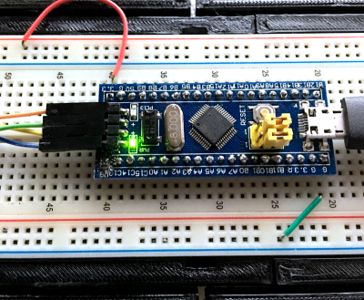
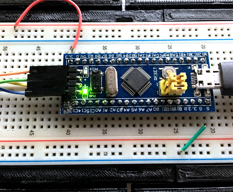
The “blue pill” designation is just a common nickname referring to the Matrix, not the pharmaceuticals you see on TV ads. The board has four pins at one edge to accommodate the ST-Link interface. The pin ordering didn’t match up with the four pins on the STM32VLDISCOVER, so you can’t just use a straight four-pin cable. You also need to bring power over to the board since it will have to power the programmer, too. I took the power from the STM32VLDISCOVER board (which is getting its power from USB) and jumpered it to my breadboard since that was handy.

The Plan

Programming the board is easy — I knew the community had done a lot of work to create a support package for it. You do need a recent version of the Arduino IDE (not the one that shows up in the default Ubuntu repositories). I downloaded version 1.8.1 from the Arduino website, just to be sure. That was the first step of my general plan of attack:

  1. Load the latest Arduino IDE
  2. Set the compile messages to verbose
  3. Use the Board Manager to install the STM32 F1 packages
  4. Get more tools
  5. Capture the build directory
  6. Run the right version of GDB

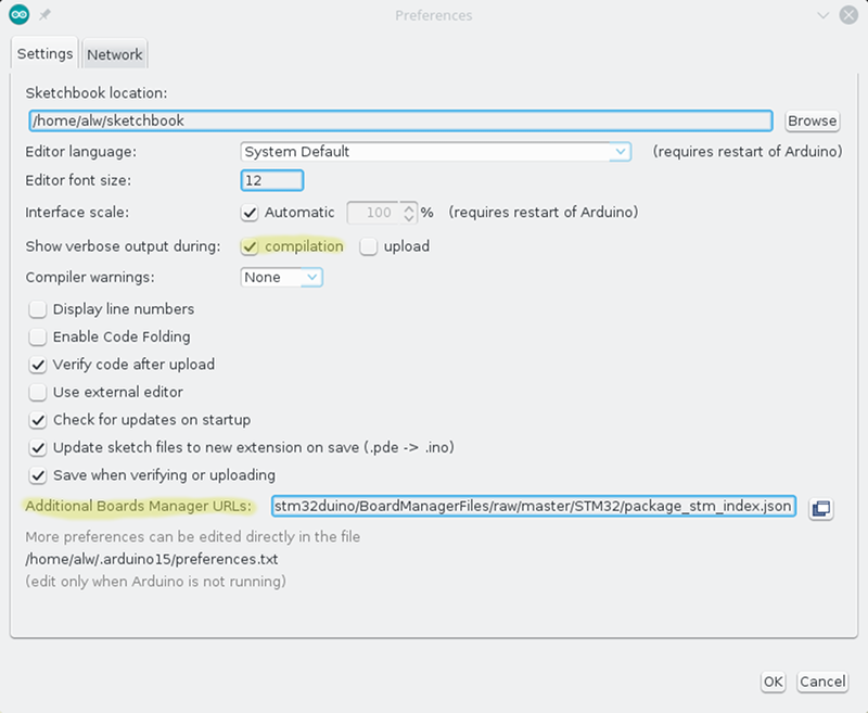
The recent versions of the Arduino IDE let you select platforms by using the Board Manager (available from the Tools | Board menu). However, if you look, you won’t see this board on the list. You’ll need to tell the IDE where to get the third-party support package. To do that, you can go to the Preferences menu item (on the File menu for Windows and Linux; I understand it is on the Arduino menu on the Mac). You need this same preferences dialog for step two, also.

Step 2 isn’t strictly necessary, but it will make step 5 easier. Just check “Show verbose output during compilation.” What you really need to know is the temporary directory the IDE uses for your build and this is the easiest way to do that, as you’ll see.

Further down the preferences screen is an entry for “Additional Boards Manager URLs.” If there’s already something there you should click the little button to edit the list. If it is empty, you can add this URL:

https://github.com/stm32duino/BoardManagerFiles/raw/master/STM32/package_stm_index.json

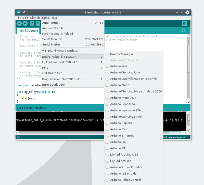
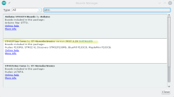
Now you can go back to the Tools | Board menu, pick Board Manager, and search for STM. You’ll probably see a few packages (I had three) but the one for the F1 will specifically mention the blue pill. Click the button to install and wait for it to do its thing.

Once installed, you’ll have some new entries on your board menu. When you have the blue pill selected, you’ll be able to pick a few options for uploading including the one we want: ST-Link.

Coding

The package has all the stuff you need to build and download programs using a variety of methods, including ST-Link. However, it doesn’t have the particular tool you need to do debugging.

It is simple enough to build the tools. The GitHub repo has the code and some simple build instructions. You do need libusb and CMake, but the page explains all that and once you have all the pieces, the build goes fast. For many OS choices, there are pre-built binaries you can use, too.

You’ll also need to know the USB ID of your ST-Link board and add it to the udev rules for Linux. If you don’t do this, you’ll need to be root to program the device and that’s not a good idea. However, depending on which ST-Link interface you use, it may already be there from other software or from the Arduino install. I’d try a test first and if it only works as root, you’ll need to update udev.

If you did your own build, I suggest running the tool stlink-gui to perform the test. You can also run st-info --descr

If you run stlink-gui, press the connect button with the ST-Link and blue pill powered up and connected. You should get the information about the device. If not, try as root. If that works, you need to update udev. I created a file, /etc/udev/rules.d/45-stlink.rules.

ACTION=="add" SUBSYSTEM=="usb", ATTR(idVendor)=="0483", 
     ATTR(idproduct)=="3744", MODE="0666", GROUP="usbusers"

You’ll need to modify that for the USB ID of your particular interface (mine was 0483:3744; the lsusb command can help). The mode allows all users to read and write the device. I made the group owner usbusers, but since everyone can access the device that probably isn’t strictly necessary.

Once you can do all that, try running the blink sketch from the IDE examples. Be sure to pick “Upload Method: STLink” from the Tools menu of the Arduino IDE. If it doesn’t work, you may need to use the tools you just built instead of the ones that come with the Arduino IDE. Mine worked but the debugging required the custom build (because the Arduino package didn’t ship with that particular tool built).

Finding the Tools and Build Directory

The Arduino IDE is pretty friendly, so it doesn’t try to install things like boards for all users, since that would require root. The board package you loaded winds up in your home directory under ~/.arduino15/packages/STM32/tools. There’s an STM32Tools directory and a few more levels down you’ll find copies of the ST-Link tools. If they don’t work, you can manually run the tools you built in the previous step to do your uploads. When we debug, we are going to do that anyway.

What’s really important though is back under the STM32/tools directory is another directory with the compiler that the IDE uses to compile your code. There’s also a matching version of GDB — the GNU Debugger — there that you will have to use.

If you loaded an example, make sure you save it to your own directory (I hate saying sketchbook). If you don’t, the IDE will make a private copy of any changes you make and things will get confusing.

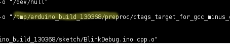
Do a build (the checkmark icon) and — assuming you checked the box in step 2 — you’ll get a lot of output from the build tools. You might verify that the compiler in use is the one we mentioned above. You’ll also see that your program gets added to other things and put in a directory named something like /tmp/arduino_build_XXXXXX where the XXXXXX is a number. Your source code will be in this directory named something like sketch/Blink.ino. In the top-level directory will be the executable Blink.ino.elf. This is what you need to debug.

If you are comfortable editing your Arduino settings file (just be sure the IDE isn’t running first) you can also force a build directory using the build.path key. The IDE does have an “export binary” command (on the Sketch menu) that compiles to your sketch folder. However, this .bin file doesn’t have enough information for the debugger.

Debugging at Last

Finally, you can debug. Use the arm-none-eabi-gdb executable from the same directory as the GCC used to compile your program. This is important. If the versions don’t match you’ll get strange errors even though many things will seem to work. Provide the name of the elf file as an argument to GDB.

If you like, you can use the -tui flag to GDB to get a sort of text-based GUI. Either way, you have one more step to go. The st-util tool you built earlier can listen to the ST-Link interface and provides a socket that GDB can use to do debugging.

Start it like this:

st-util -p 1234

That will make it listen on port 1234. If you already use that port for something else, pick another one. Just remember that on Linux only root can listen on ports below 1024, so pick a bigger number.

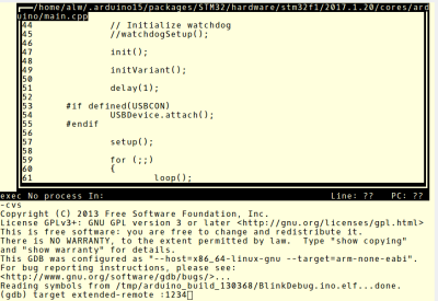
Once that is running, you fire up GDB with your elf file name and issue the command:

target extended-remote :1234

Or, I’ve recently started using:

target remote :1234

You can run the two parts on different computers, so use a hostname if necessary (that is, devbox21:1234). Most times, the programs are on the same box and you can use localhost or omit it like I did. The difference between remote and extended-remote is that the server does not shut itself down at the end of an extended-remote session. It often works, but I have seen cases where I had to restart the server anyway, so lately I’ve been using plain-old remote to force me to restart it with each session.

A “load” command to GDB will now flash your program to the board. A typical session after a load might be:

break main
continue
list
n
n
n

The “n” command steps to the next instruction.You can find a lot more about using GDB in an earlier post. You also might find it easier to watch the walkthrough in this video:

A few caveats. First, optimization can cause your lines to execute out of order, or even go backwards. It can also cause variables to not be visible where they have been optimized out. The other thing to watch out for is that, in some cases, the debugger internally single steps. This can cause very slow execution of delay routines, for instance. You might reduce or remove delays while debugging or be careful where you try to single step instead of placing breakpoints.

Final Thoughts

It would be neat if the Arduino IDE let you debug inside of it. However, there are ways to do that using Eclipse (and GDB) or Visual Studio (if you use Windows). If you are like me and OK with the command line, you might think about using one of the Makefiles for Arduino instead of the IDE. If you aren’t OK with the command line, there are GUI shells for GDB that you could try. If you’d rather hack the ST-Link firmware, we’ve seen that done, too. If you miss doing printf’s, you might want to try a Black Magic probe, which ought to work about the same as the ST-Link interface, but also provides a serial port for printf and other mischief.

By the way, Arduino isn’t the only choice for this board. It is possible to use mBed and other development tools with them. But that’s a topic for a future post.


Filed under: Arduino Hacks, ARM
Hack a Day 30 Mar 18:01

Acoustic Coupler Pole-Vaults Over China’s Firewall

[agp.cooper]’s son recently went to China, and the biggest complaint was the Great Firewall of China. A VPN is a viable option to get around the Great Firewall of China, but [agp] had a better idea: an acoustic coupler for his son’s iPhone.

Hackaday readers of a recent vintage might remember an old US Robotics modem that plugged into your computer and phone line, allowing you to access MySpace or Geocities. Yes, if someone picked up the phone, your connection would drop. Those of us with just a little more experience under our belts will remember the acoustic coupler modem — a cradle that held a phone handset that connected your computer (indirectly) to the phone line.

With a little bit of CNC work, [agp] quickly routed out a block of plywood that cradled his son’s iPhone. Add in a speaker and a microphone, and that’s an acoustic coupler. There’s not much to it, really. The real challenge is building a modem.

In the late 90s, there were dedicated chipsets for modems, and before that, there was a 74xx-series chip that was a 300-baud modem. [agp] isn’t using anything like that. He’s building a modem with an Arduino. This is a Bell 103A-compatible modem, allowing an iPhone to talk to a remote computer at 300 bits per second. This is a difficult challenge; we’re not able to get 33kbps over a smartphone voice connection simply because of the codecs used. However, with a little bit of work, [agp] managed to build a real modem with an Arduino.


Filed under: Arduino Hacks

Panel Mount Display Solves The Problem Of Drilling Square Holes

[Absolutelyautomation] has a problem with seven-segment displays. Fitting these displays in an enclosure is a pain because you can’t drill perfectly square holes, and you will invariably mess up a few enclosures with overzealous file work. There is a solution to this problem – panel mount meters.

The bezels on these panel mount meters hide the imperfections in the enclosure, and usually don’t require screws. They are, however, dedicated displays, usually for temperature, RPM, or some other measurement.

[Absolutelyautomation] took one of these dedicated panel mount displays and turned it into an all-purpose device. Basically, it’s a panel mount Arduino with three seven-segment displays.

This project is built on perfboard cut down to fit inside the enclosure of a very cheap panel meter found at the usual suppliers. Tucked away underneath this perfboard is an ATmega, a few resistors, and the support parts to make everything go. This panel mount meter can either be a serial slave or as a standalone controller, programmable with the Arduino IDE. It’s cheap, too. You can check out [Absolutelyautomaion]’s video below.


Filed under: Arduino Hacks

The Custom Clicky Shortcut Keypad

You’re not cool unless you have a mechanical keyboard. Case in point: if you were to somehow acquire an identical keyboard to the one I used to type this, it would set you back at least seven hundred dollars. Yes, it’s mechanical (Topre), and yes, I’m cooler than you. Of course, you can’t be as cool as me, but you can build your own mechanical keyboard. [Robin] is, I presume, a pretty cool dude so he built his own keyboard. It’s the amazing shortcut keyboard, and it can be programmed graphically.

The idea for this keyboard came when [Robin] was studying as an engineer. We assume this is code for wearing out the Escape key on AutoCAD, but many other software packages have the same problem. The solution to [Robin]’s problem was a shortcut keypad, a 3 by 4 matrix of Cherry switches that could be programmed for any task.

The design of this keyboard started out as an Adafruit Trellis matrix keypad. This was combined with some software written in Processing that assigned macros to each button. This was a sufficient solution, but the switches in the Adafruit trellis look squishy. These are not the right switches for someone who craves a soft snap under every fingertip. It’s not the keyboard of someone who desires the subtle thickness of laser etched PBT keycaps. The Adafruit keypad doesn’t have the graceful lines of a fully sculpted set of keycaps. Oh my god, it’s doubleshot.

[Robin]’s completed keyboard has gone through a few revisions, but in the end, he settled on PCB-mounted switches and a very clever 3D printed standoff system to hold an Arduino Pro Micro in place. The enclosure, too, is 3D printed, and the end result is a completely custom keyboard that’s perfect for mashing key combos.

You can check out a video of this keyboard in action below.


Filed under: Arduino Hacks, peripherals hacks

The Altair Shield

From PDPs to Connection Machines, the Hackaday crowd are big fans of blinkenlights. While this project isn’t an old CPU, RAM, ROM, and an S-100 bus wrapped up in a fancy enclosure, it is a great recreation of the Altair 8800, the historic kit computer that supposedly launched the microcomputer revolution.

[Justin] says his project is just another Altair 8800 clone, but this one is cut down to the size of an Arduino shield. This is in stark contrast to other Altair recreations, whether they are modern PCs stuffed in an old case, modern replicas, or a board that has the same functionality using chunky toggle switches.

On board [Justin]’s pocket-sized Altair are a few LEDs, some DIP switches, and an octet of spring-loaded dual throw switches that wouldn’t look out of place in a 40-year old computer.

This shield targets the Arduino Due rather than the Mega, but only because the Due performs better running an Altair simulation. Everything is there, and a serial terminal is available ready to run BASIC or any other ancient OS.


Filed under: Arduino Hacks

Pulse Oximeter is a Lot of Work

These days we are a little spoiled. There are many sensors you can grab, hook up to your favorite microcontroller, load up some simple library code, and you are in business. When [Raivis] got a MAX30100 pulse oximeter breakout board, he thought it would go like that. It didn’t. He found it takes a lot of processing to get useful results out of the device. Lucky for us he wrote it all down with Arduino code to match.

A pulse oximeter measures both your pulse and the oxygen saturation in your blood. You’ve probably had one of these on your finger or earlobe at the doctor’s office or a hospital. Traditionally, they consist of a red LED and an IR LED. A detector measures how much of each light makes it through and the ratio of those two quantities relates to the amount of oxygen in your blood. We can’t imagine how [Karl Matthes] came up with using red and green light back in 1935, and how [Takuo Aoyagi] (who, along with [Michio Kishi]) figured out the IR and red light part.

The MAX30100 manages to alternate the two LEDs, regulate their brightness, filter line noise out of the readings, and some other tasks. It stores the data in a buffer. The trick is: how do you interpret that buffer?

[Raivis] shows the code to take the output from the buffer, remove the DC component, pass it through a couple of software filters, and detect the heart rate. To read the oxygen reading, you have even more work to do. You can find the code for the device on GitHub.

If you want to build your own without a dedicated IC, grab a clothespin. Or try this more polished build.


Filed under: Arduino Hacks, Medical hacks

Save ESP8266 RAM with PROGMEM

When [sticilface] started using the Arduino IDE to program an ESP8266, he found he was running out of RAM quickly. The culprit? Strings. That’s not surprising. Strings can be long and many strings like prompts and the like don’t ever change. There is a way to tell the compiler you’d like to store data that won’t change in program storage instead of RAM. They still eat up memory, of course, but you have a lot more program storage than you do RAM on a typical device. He posted his results on a Gist.

On the face of it, it is simple enough to define a memory allocation with the PROGMEM keyword. There’s also macros that make things easier and a host of functions for dealing with strings in program space (basically, the standard C library calls with a _P suffix).

However, there’s also a helper class that lets you use a string object that resides in program memory. That makes it even easier to use these strings, especially if you are passing them to functions. As an example [sticilface] writes a string concatenation function that handles PROGMEM strings.

You can use the same techniques for other data, as well, and at the end of the post, there are some very clear examples of different use cases. Under the hood, the ESP8266 doesn’t store data in bytes in program memory. The library routines hide this from you, but it can be important if you are trying to calculate space or do certain kinds of manipulation.

You can also check out the official documentation. If you want to see the technique in action, maybe you’ll be interested in your coworker’s mood. Or, try putting a Jolly Wrencher on your oscilloscope. Both projects use PROGMEM.

[Editor’s note: PROGMEM is in the ESP8266 Arduino codebase from AVR-GCC, and originally wrote (counterinutitively) into RAM.  Some clever hacking fixed that early last year, so now you can use the same AVR-style abstraction with the ESP. It still doesn’t work on the ARM Arduinos.]

Image by [connorgoodwolf] (CC BY-SA 4.0)


Filed under: Arduino Hacks

Arduino into NAND Reader

[James Tate] is starting up a project to make a “Super Reverse-Engineering Tool”. First on his list? A simple NAND flash reader, for exactly the same reason that Willie Sutton robbed banks: because that’s where the binaries are.

As it stands, [James]’s first version of this tool is probably not what you want to use if you’re dumping a lot of NAND flash modules. His Arduino code reads the NAND using the notoriously slow digital_read() and digital_write() commands and then dumps it over the serial port at 115,200 baud. We’re not sure which is the binding constraint, but neither of these methods are built for speed.

Instead, the code is built for hackability. It’s pretty modular, and if you’ve got a NAND flash that needs other low-level bit twiddling to give up its data, you should be able to get something up and working quickly, start it running, and then go have a coffee for a few days. When you come back, the data will be dumped and you will have only invested a few minutes of human time in the project.

With TSOP breakout boards selling for cheap, all that prevents you from reading out the sweet memory contents of a random device is a few bucks and some patience. If you haven’t ever done so, pull something out of your junk bin and give it a shot! If you’re feeling DIY, or need to read a flash in place, check out this crazy solder-on hack. Or if you can spring for an FTDI FT2233H breakout board, you can read a NAND flash fast using essentially the same techniques as those presented here.


Filed under: Arduino Hacks, hardware