Posts with «uno» label

Squeeze through pipes with this six-wheeled robot

If you need a robot to traverse piping systems, what are you to do? You could purchase a (very expensive) inspection robot, or you could instead build your own like the prototype pipe-crawler presented here. 

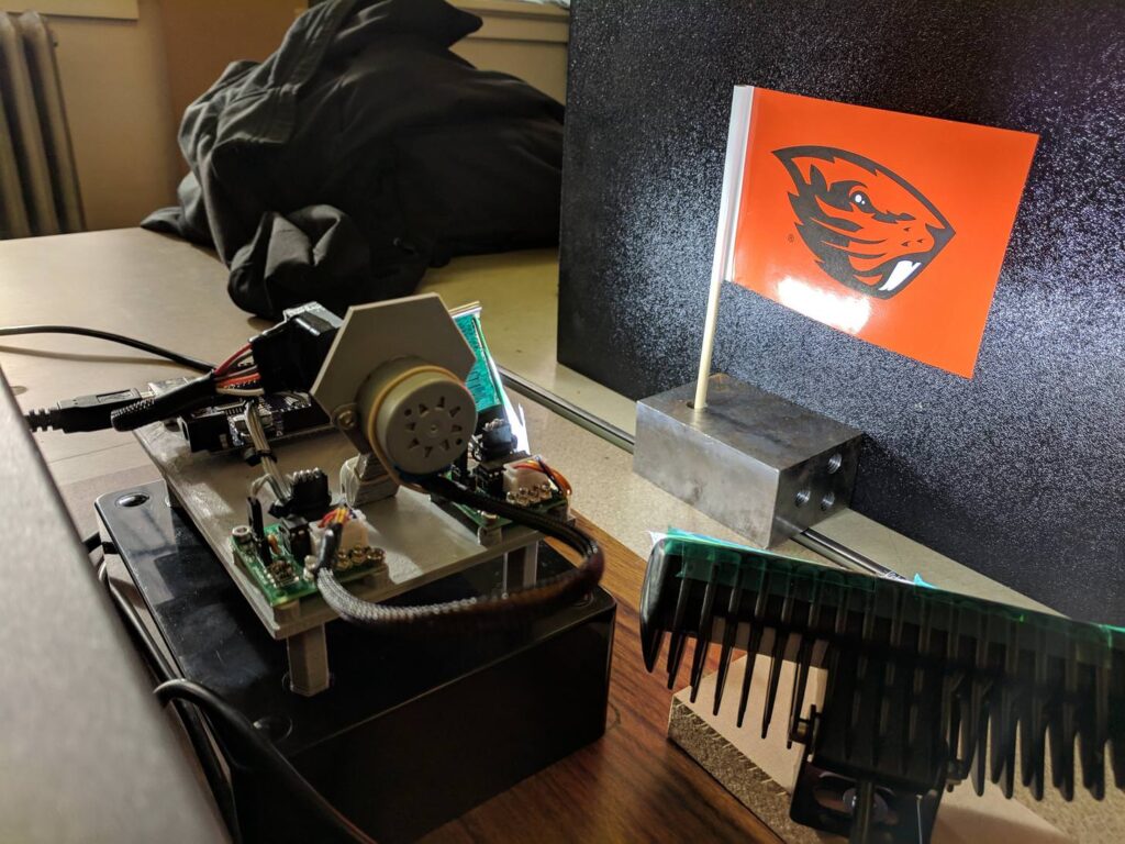
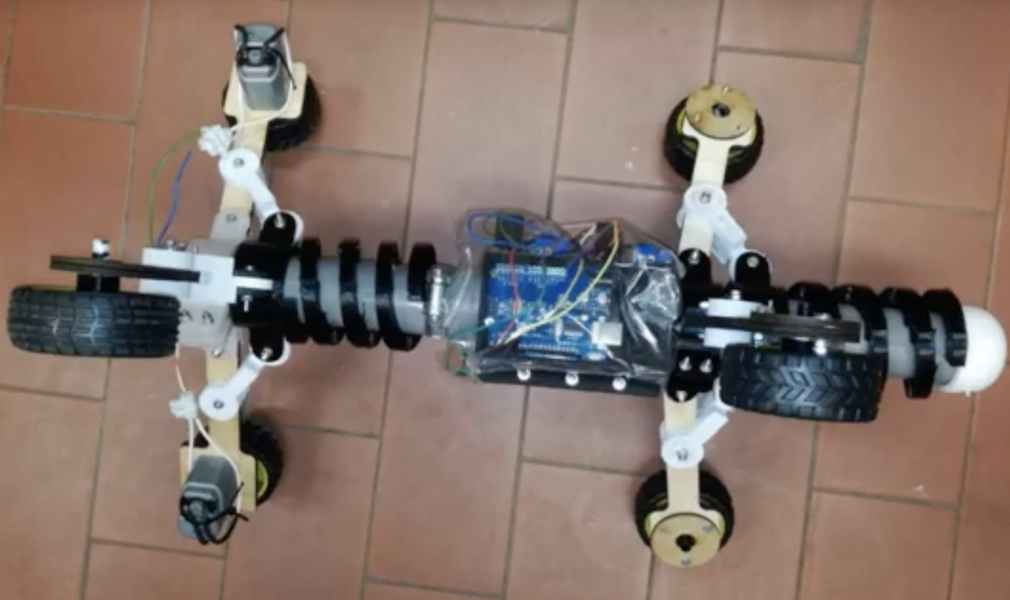
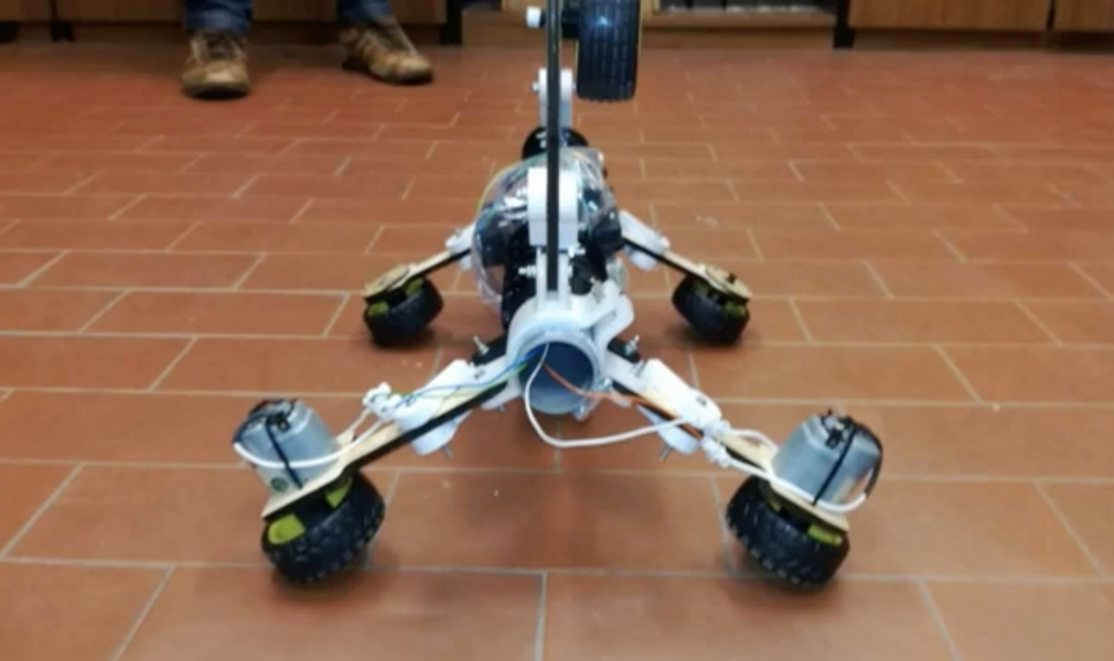
The device features six spring-loaded wheel assemblies that help it get a grip on different diameters of pipe, with two of the wheels powered for locomotion.

An Arduino Uno controls the uniquely-shaped bot, with an LN298N H-bridge used to regulate the three 9V batteries wired in series that run the motors. 

Pipeline systems deteriorate progressively over time through various means. Pipeline inspection robot are designed to remove the human factor from labour intensive or dangerous work environments and also to act in inaccessible environment. However, if you take a look at the prices of those robots you will find that they are way too expensive.

This project aims to create another kind of pipeline inspection robot. Because we think that It is beneficial to have a robot with an adaptable structure to the pipe diameter, and cheaper at the same time.

Our challenge is to make this robot adaptable to diameters varying from 260mm to 390mm based on two sliding mechanisms.

Be sure to see it in action in the short video below! 

Control model trains wirelessly with your smartphone

Model trains have been a staple of DIY hobbiysts for generations, and while wireless control options can be purchased, KushagraK7’s hack lets you use your phone instead.

The setup consists of an Arduino Uno, along with a motor driver shield to vary the trains’s peed and direction, as well as flip turnouts to allow for different sections of track to be used.

The system employs a novel interface system, where an off-the-shelf Bluetooth receiver passes DTMF (telephone dial tones) to a decoder board, which then sends this decoded data on to the Arduino. While some might opt for an HC-05 Bluetooth module or similar, this enables control with a standard tone generator app, and the phone could even be physically connected via a stereo cable if convenient.

Arduino and Pi Share Boardspace

A Raspberry Pi Zero (W) and Arduino are very different animals, the prior has processing power and connectivity while the latter has some analog to digital converters (ADCs) and nearly real-time reactions. You can connect them to one another with a USB cable and for many projects that will happily wed the two. Beyond that, we can interface this odd couple entirely through serial, SPI, I2C, and logic-level signaling. How? Through a device by [cburgess] that is being called an Arduino shield that supports a Pi0 (W). Maybe it is a cape which interfaces with Arduino. The distinction may be moot since each board has a familiar footprint and both of them are found here.

Depending on how they are set up and programmed, one can take control over the other, or they could happily do their own thing and just exchange a little information. This board is like a marriage counselor between a Raspberry Pi and an Arduino. It provides the level-shifting so they don’t blow each other up and libraries so they can speak nicely to one another. If you want to dig a bit deeper into this one, design files and code examples are on available.

Perhaps we’ll report on this board at the heart of a pinball machine retrofit, a vintage vending machine restoration, or maybe a working prop replica from the retro bar in Back to the Future II.

An inexpensive device for analyzing roasted coffee beans

While you may not consider in detail how your coffee is roasted, those that produce it must pay special attention to make sure that the end product is consistent. Equipment to help analyze roasted coffee is normally quite expensive, but using a near-infrared sensor, Arduino Uno and Bluetooth module, Spencer Corry was able to make his own analysis setup.

As shown in the video below, after calibration, beans are inserted into the analysis chamber using a tryer scoop. Light is shined onto the roasted beans, and the intensity of the reflected near-infrared radiation is analyzed in six different wavelengths. Intensity data is then transmitted via Bluetooth to a smart device, which can be used to make sure things are roasted perfectly.

There has recently been a growth of small roasting companies offering custom in-house roasts. These companies are looking for less expensive alternatives to hiring and training a roast master or using the expensive Agtron Process Analyzer. The Degree of Roast Infrared Analyzer for Coffee Roasters, as described in this document, is meant to be an inexpensive means of measuring the degree of roast of coffee beans. The Degree of Roast Infrared Analyzer uses a tryer, a tool found on coffee roasters used to sample the coffee during roasting, to hold a sample of coffee. The tryer is inserted into the analyzer where the AS7263 NIR Spectral sensor is used to measure 6 different infrared bands (610, 680, 730, 760, 810, and 860nm). The reflectance measurements are transmitted via Bluetooth and can then be correlated to the degree of roast. The analyzer must first be calibrated by pressing a button on the inside of the box in which the PVC is used as a white balance as it has a relatively flat reflectance in the spectral range detected by the sensor.

An Arduino-based rocket motor thrust test stand

If you enjoy model rocketry, you may wonder just what the thrust curve of the motors you’re using looks like. In order to answer that question, YouTuber ElementalMaker decided to construct his own test stand using an Arduino Uno coupled to a 10Kg load cell with an HX711 amplifier board. The test procedure is started with a little red button, and after warning LED blinks away for 10 seconds, it activates a relay and fires the motor under into the stand.

The experimental setup seen in the video yields successful thrust curves for both a ½ inch and ¾ inch motor. As you might expect, the ¾ produces more thrust than its smaller cousin, though at 2,683 grams versus the ½ inch motor’s 658, it’s an impressive difference indeed. 

The heart of the stand is a common load cell (the sort of thing you’d find in a digital scale) coupled with a HX711 amplifier board mounted between two plates, with a small section of vertical PVC pipe attached to the topmost plate to serve as a motor mount. This configuration is capable of measuring up to 10 kilograms with an 80Hz sample rate, which is critically important at this type of rocket motors only burn for a few seconds to begin with. The sensor produces hundreds of data points during the short duration of the build, which is perfect for graphing the motor’s thrust curve over time.

Given such a small window in which to make measurements, [ElementalMaker] didn’t want to leave anything to chance. So rather than manually igniting the motor and triggering the data collection, the stand’s onboard Arduino does both automatically. Pressing the red button on the stand starts a countdown procedure complete with flashing LED, after which a relay is used to energize a nichrome wire “electronic match” stuck inside the motor.

The project is based on a paper archived here if you’d like to examine the design.

Build a single-pixel scanning camera with an RGB sensor

Sensors like the TCS34725 from Adafruit can detect a single color. It stands to reason then, that if you were to aim this sensor at a multitude of points and record the resulting data, you could have a one-pixel camera. As seen here, Tucker Shannon decided to take this concept and run with it, constructing his own with an Arduino Uno and a pair of stepper motors.

The device looks like something akin to some sort of auto-turret, and directs the sensor in a square spiral for image acquisition. The resulting pictures are certainly low-res, but good enough to pick out recognizable forms with a little imagination. 

The color sensor tells the Arduino what color it “sees” at any given time. By pointing it at every single point within a field of view, I can record these colors and use them later to reconstruct an image.

Using two stepper motors, the camera points the sensor at every “pixel” within the photo and records what it sees. It uses these values to “paint” a picture of whats in front of it!

Components include: 1x Arduino Uno, 1x Adafruit RGB Color Sensor TCS34725, x2 BYJ-48 Stepper motor with drivers, x1 3mm OD aluminum tube, x20 M3x6mm fasteners. Alternatively a photoresistor can be used in place of the RGB sensor for black and white photos!

Code for the project can be found on GitHub, and print files are on Thingiverse if you’d like to build your own!

Keep track your weekly tasks with Arduino and arcade buttons

All of us have daily tasks we need to perform, but what if you often forget whether you’ve done something, or simply need to give your child a little extra motivation? One great way would be Simon Prickett’s Arduino Task Tracker, inspired by Simone Giertz’s Every Day Calendar. 

Prickett’s clean-looking device is built into an electrical junction box, which holds the guts, including an Arduino Uno inside. It also exposes eight arcade-style LED buttons on top.

After you, or in this case Prickett’s son, complete a chore, press one of the seven green buttons. Once they are all lit, the Arduino Task Tracker produces a “victory roll” sequence. The eighth red button is then used to start the week over again. 

Sound like something you’d like to recreate? Code and more info for the project can be found GitHub.

Mood-controlled RGB light wall

In the build shown below, Evan McMahon dares to ask the question, “Have you ever been disappointed by a mood ring?” While that might seem a bit random, the answer is a likely “yes” if you’ve ever worn one with the expectation of any sort of accuracy. Fortunately, he didn’t just pose the question, but also came up with a clever solution, using an array of lights under Arduino control.

For the setup, McMahon uses the camera on his iPhone to take video of his smiling or frowning mug, then analyzes it with the help of Unity running on a computer to translate this into his apparent state of mind.

This info is then sent to an Arduino Uno, which puts the programmable LED lights into dance mode if he’s happy, and makes them shine blue if he’s a bit blue himself!

Arduino Blog 05 Dec 14:44

Simple PID control intro device

You may have come across the term “PID control,” and while this proportional-integral-derivative control method does a great job of smoothing out oscillations, where does one get started? 

One solution would be Mr Innovative’s demo device, showcased in the video below. In it, a DC gear motor is able to smoothly rotate an arrow overlaid on a protractor by a certain number of degrees.

Input is via a Bluetooth smartphone interface, and an encoder is used for feedback to the commanding Arduino Uno. Everything is fastened together by 3D-printed parts, and if you’d like to try your own PID experiment, code and print files are linked in the video description.

Keyboard dampener prototype aims to reduce typing injuries

While we don’t normally think of typing on a computer as a dangerous job, the U.S. Department of Labor reports that workers spend 25,000 hours away from work due to repetitive strain injuries, such as using a computer. Part of this could be due to the fact that the average computer user applies two to seven times the necessary force needed to activate a keyboard’s keys, slamming them down, then experiencing a sudden stop.

In order to help cushion these small blows, researchers Alec Peery and Dušan Sorma at Ohio University have been exploring a mechanical keyboard concept with a 3D-printed dampener built in. Testing has been undertaken using the popular Cherry MX switches, with typing simulated by dropping a 150 gram cylinder from 125mm, then measured using an Arduino Uno and force sensing resistor.

This paper is a demonstration of how 3D printing can be used to create a composite (plastic and rubber) keyboard switch that is ergonomically superior to a traditional injection moulded plastic switch. The prototype switch developed in this project aims to reduce impact forces from keyboard use exerted on user’s fingers by “cushioning” the act of bottoming out the switch during a key press. This concept is significant to industry because it aims to reduce overuse injuries caused from work on computer, a portion of the $20 Billion a year owed in worker compensation in the United States. A commercial Cherry MX keyboard switch has been modified through CAD modelling and 3D printing to incorporate damping regions in the lower half of the switch housing. The switch housings were simultaneously 3D printed with plastic and rubber and their force damping properties were tested with an Arduino UNO microcontroller and force sensing resistor resting on the key tops.

The full research paper is available here.