Posts with «tutorial» label

DIY Arduino Watch

We first thought [Alexis Ospitia]’s watch was a sports watch made with an Arduino, but it’s actually a sporty watch made with an Arduino. This explains the watch’s strange ability to tell you the current temperature and humidity.

The core of the watch is an Arduino Mini. To make it good for time telling, a real-time clock module was added. A DHT11 monitors the temperature and humidity. A charge circuit and lithium battery provide power. Finally, the watch displays the date, time, and other data with an LCD from a Nokia 5110. We can tell you the last part that’s going to break on this.

Even if you think the watch is a bit chunky, the tutorial is very slick. [Alexis] has taken the trouble to individually draw and describe each portion of the watch’s construction. He explains each pin, what they do, and provides a Fritzing drawing of the wires to the Arduino. The code is provided; to program the watch a USB-to-serial module must be used.

For the housing he made a box from a thin gauge aluminum sheet and attached leather straps to the assembly. The final construction is cool looking in a techno-punk way, and is fairly compact. One might even say sporty.


Filed under: Arduino Hacks
Hack a Day 22 Apr 00:00

Massimo Banzi’s guest judge at America’s greatest makers

Massimo Banzi is among the judges on “America’s Greatest Makers” a reality competition from Mark Burnett (the reality-TV king behind “Survivor,” “The Apprentice,” and “The Voice”) in partnership with Intel which debuted last week on TBS.

In a first of its kind competition, the tv show takes 24 teams of makers from across US and puts them in head-to-head challenges to invent disruptive projects and win $1 million. The team are composed by unique people from 15 years old to 59 with ideas going to inspire a whole new audience of potential makers.


In the first two episodes, each team pitched their device idea to the judging panel composed by Intel CEO Brian Krzanich; business and financial expert Carol Roth; comedian, serial entrepreneur and co-host of truTV’s Hack My Life Kevin Pereira; and one of the celebrity guests.

At the end of April during 4th episode guest judge Massimo Banzi joins the panel as the remaining makers compete in the “Make or Break” rounds for $100,000 and a spot in the million dollar finale. If you are not in the USA, watch the episode at this link after April 27th.

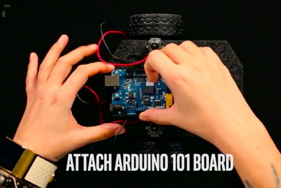
In the meanwhile you can also watch a beginner maker project to learn how to do obstacle avoidance using Arduino 101. Cara Santa Maria is the trainer who’s going to guide you into the tutorial about this really important topic for projects involving moving objects like robots and drones:


Follow the show on Twitter, Instagram, Facebook and use hashtag #AmericasGreatestMakers


An Arduino-based Cellular Automata with OLED monitor

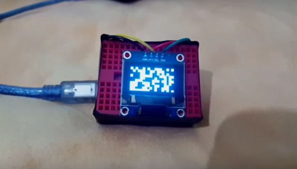
RuntimeProject made a tutorial to create a little cellular automata on a small 126×64 OLED using Arduino Nano.

He worked on one type of cellular automata, the Game of Life by John Conway, which has a grid of cells each having 2 states True or False/on or off/alive or dead. These cells are governed by 2 simple rules:

Rule 1: A cell which is dead and is surrounded by exactly 3 alive cells, will be born

Rule 2: A cell which is alive and has either 3 or 2 alive cells will remain alive, else it dies

The Arduino-based Cellular Automata works using 2 libraries the,  Adafruit GFX library  to handle all graphics and text displayed on the OLED;
Adafruit SSD1306 library which is the driver for the OLED.

You can read more info on how to make it on his blog and download the sketch on Github.

You Can Build Arduino multi-device Networks with Temboo

Is there a cool Internet of Things idea that you’ve wanted to try out with your Arduino, but just haven’t had time for?  Building a network that integrates multiple sensors and boards into one cohesive application can be time-consuming and difficult.  To make it a bit easier, Temboo just introduced new Machine-to-Machine programming that lets you connect Arduino and Genuino boards running locally in a multi-device network to the Internet.  Now, you can bring all the power and flexibility of Internet connectivity to Arduino applications without giving up the benefits of using low power, local devices.

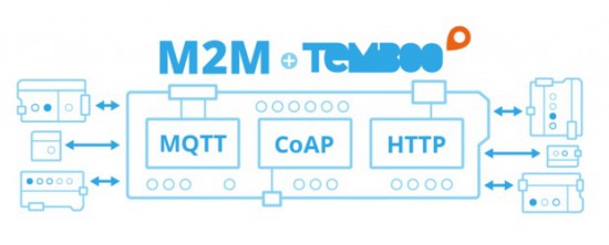
Our friends at Temboo now support three M2M communication protocols for Arduino boards: MQTT, CoAP, and HTTP. You can choose which to use based on the needs of your application and, once you’ve made your choice, automatically generate all the code you need to connect your Arduinos to any web service. You can also save the network configurations that you specify, making it easy to add and subtract devices or update their behavior remotely.

With Temboo M2M, you can program flexible distributed device applications in minutes. From monitoring air quality and noise levels in cities to controlling water usage in agricultural settings, networked sensors and devices enable all sorts of powerful IoT applications. You can see it all in action in the video below, which shows how they built an M2M network that monitors and controls different machines working together on a production line.

Arduino Blog 15 Dec 17:02

Make your DIY smart glasses running on Arduino

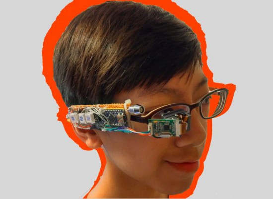
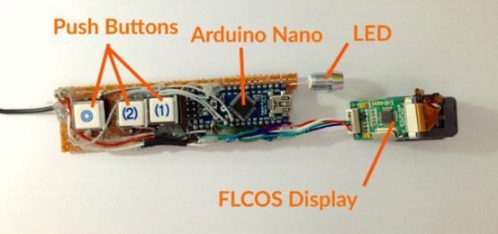
Jordan Fung is a 13-year-old maker and programmer based in Hong Kong. He recently developed Arduino-based smart glasses called Pedosa Glass, which are able to activate, in this first release, a flashlight and a timer:

The Pedosa Glass is powered by a single Arduino Nano running an “operating system” developed by me.
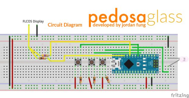
There is a tiny FLCOS display in the front. The AV signal from the Arduino will be displayed on it. It is equipped with 3 push buttons, in which 2 of them are control buttons and one of them be the home button, also equipped with a super-bright white LED for use as a flashlight.

In the picture below you can explore the electronic scheme:


Jordan is working hard to add new applications and features to the project but in the meanwhile he shared his work on a great tutorial on Instructables.

Slap my zombie hand for internet fame!

Halloween time is a great moment to explore nice interactive projects and get inspired for installations for other selfie occasions. To spice up the office Donnie Plumly, a creative technologist, decided to make and share with us a molded zombie arm that takes pictures and post them to Twitter.

He used a silicone arm (molded on his own hand ), a custom steel mount to clip to an office partition, and a vibration sensor hooked up to an Arduino Uno. Once the arm is slapped a photo will be taken using an IR Led and passed to the Eye-Fi card in the camera.

The photo is then saved into a Dropbox folder and, using If This Then That (IFTTT), posted to Twitter on the account @ZombieSelfie.

Donnie created also a very useful tutorial  on Instructable to make it yourself!

Arduino LED Light Box

Description

Long straight lines of LED luminescence is nice, but sometimes you may want to light up something that has an unusual shape, or is not so linear. This is where the 12mm diffused flat digital RGB LED Pixels can come into play. This cool strand of 25 NeoPixels fit nicely into 12mm pre-drilled holes of any material you like.

This tutorial is dedicated to making a LED Light Box. I wanted the box to be equally as interesting during the day as it was at night. If you decide you make your own, feel free to be as creative as you want !! However, if you lack artistic acumen, you may need to source a minion or two.


Arduino Libraries and IDE

Before you start to hook up any components, upload the following sketch to the Arduino microcontroller. I am assuming that you already have the Arduino IDE installed on your computer. If not, the IDE can be downloaded from here.

The FastLED library is useful for simplifying the code for programming the NeoPixels. The latest "FastLED library" can be downloaded from here. I used FastLED library version 3.0.3 in this project.

If you have a different LED strip or your NeoPixels have a different chipset, make sure to change the relevant lines of code to accomodate your hardware. I would suggest you try out a few of the FastLED library examples before using the code below, so that you become more familiar with the library, and will be better equipped to make the necessary changes.

If you have a single strand of 25 Neopixels with the WS8201 chipset, then you will not have to make any modification below.


ARDUINO CODE:

Arduino Code Description

The code above will generate a randomised raindrop pattern on the NeoPixel LED Light box, however I have written code for a few more LED animations. These animations were written specifically for this light-box setup. In other words, once you have hooked everything up, you will be able to upload these other LED animations to the Arduino board without any further modification to the hardware/wiring, and yet experience a totally different light effect. You can find the code for the other animation effects by clicking on the links below:

  1. Breathing effect
  2. Ripple effect
  3. Clock effect
  4. Rotation effect
  5. Sweep effect
  6. Spiral effect
  7. Lightning effect
  8. Paparazzi in the Rain effect

Hooking it up:

Power requirements

Each Neopixel LED can draw up to 60 milliamps at maximum brightness (white). ie. 20 mA for each colour (red, green and blue). Therefore you should not try to power the LED strand directly from the Arduino, because the strand will draw too much current and damage the microcontroller(and possibly your USB port too). The LED strand will therefore need to be powered by a separate power supply. The power supply must supply the correct voltage (5V DC) and must also be able to supply sufficient current (1.5A or greater per strand of 25 LEDs).

Excessive voltage will damage or destroy your Neopixel strand. The LEDs will only draw as much current as they need, however your power supply must provide at least 1.5A or greater for each strand. If you chain two strands together, you will need a 5V 3A power supply.

Neopixel strand connection

There are 25 Neopixel LEDs per strand. Four of the wires at each end of the strand are terminated with a JST connector. The red wire is for power (VCC), blue wire for ground (GND), yellow wire is for Data, and green wire for Clock. A spare red wire (VCC) and a spare blue wire (GND) are attached to the ends of each strand for convenience, however, I did not use either. Please double check the colour of your wires... they may be different.

If you want to attach the LED strand to a breadboard, you can cut the JST connector off and use the Neopixel strand wires. Alternatively, if you would prefer to preserve the JST connector, you can simply insert jumper wires (or some male header pins) into the JST connector, and then plug them into the breadboard as required.

Each neopixel LED is individually controllable using two pins on your Arduino. The strand is directional. i.e. There is an INPUT side and an OUTPUT side. The strand should be connected such that wires from the microcontroller are attached to the INPUT side of the first neopixel. The arrows on each LED show the direction of data flow from INPUT to OUTPUT. The arrow on the first NeoPixel should be pointing towards the second NeoPixel, NOT towards the breadboard.

Other considerations

As a precaution, you should use a large capacitor across the + and - terminals of the power supply to prevent the initial onrush of current from damaging the Neopixels. I used a 4700uF 16V Electrolytic capacitor for this purpose. According to Adafruit, a 1000uF 6.3V capacitor (or higher) will also do the trick. You may also want to consider a 330 ohm resistor between the Arduino Digital pin and the strand's DATA pin.

If you want to power the Arduino using the regulated 5V external power supply. Disconnect the USB cable from the Arduino, and then connect the positive terminal of the power supply to the 5V pin on the Arduino. Be warned however, that excess voltage at this pin could damage your Arduino, because the 5V regulator will be bypassed.
 
Providing the USB cable is NOT connected to the Arduino, it should now be safe to plug the power supply into the wall. This setup will allow you to power the Neopixel strand and the Arduino using the same power supply.
 
WARNING: Never change any connections while the circuit is powered.

For more information about these NeoPixel strands, you may want to visit the Adafruit site. Adafruit was the source for most of these NeoPixel Strand precautions.


Fritzing diagram

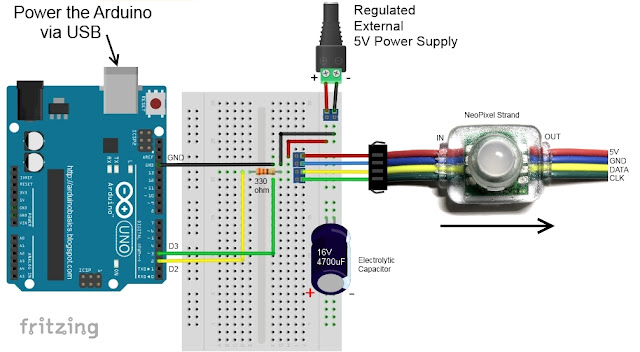
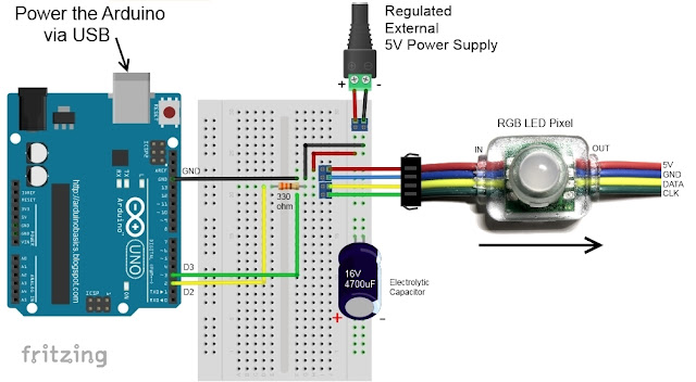
The following diagram demonstrates how to connect the NeoPixel Strand to the Arduino and to the External 5V power supply.


This diagram was created using Fritzing


Connection Instructions

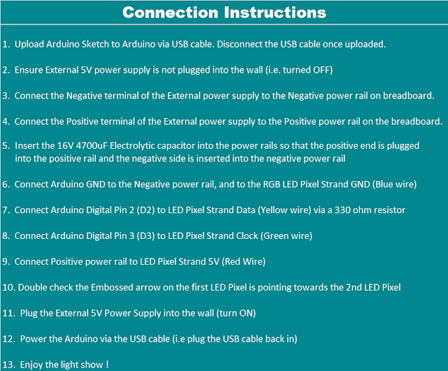
These instructions will help to guide you through the process of connecting your NeoPixel strand to the Arduino, and to the external power supply. The instructions assume that you will be powering the Arduino via a USB cable.


LightBox assembly

You will need to drill a 12mm hole into the craft timber box for each LED on the strand. It is worth taking the time to make accurate measurements before drilling the holes.
 
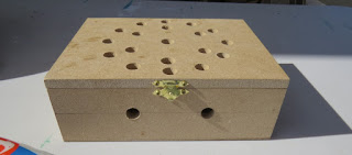
I made 12 holes for the outside circle pattern (12cm diameter), 6 holes for the inside circle pattern (8cm diameter), and a hole in the centre. I also made two holes at the front of the box, two on the left side, and two on the right side. I made one last hole at the back of the box for the 2.1mm DC power line socket.
 
Therefore you should have a total of 26 holes in the box. 25 of the holes are for the Neopixel LEDs and one for the external power supply socket.

The lid of the box is about 19.5cm x 14.5cm long, which makes for a very tight squeeze. Probably too tight, because you have to account for the inner dimensions of the box. The inside of the box is used to house the Arduino, breadboard, the chipset side of the LEDs and cables/components. The inner dimensions of the box are 18cm x 13cm. Therefore, the housing for the LED chipset PCB (1.8cm x 2.5cm) prevented the box from closing. I used a Dremel to carve out the space required to close the lid.

Each LED is approximately 8cm apart on the strand, however, if you are really keen, you could cut the wires and extend them to any distance you require. But keep in mind that each LED is mounted on a small PCB (with a WS2801 chipset).You will therefore need to leave a minimum of 2cm between each 12mm hole to accomodate the size of the PCB+LED. If you plan carefully, you can probably squeeze a couple of LEDs within a distance of 1cm... but I would recommend that you give yourself a bit more room, because the PCBs are not square, and there is a good chance that you will have to start all over again.

In hindsight, I could have made the circle patterns a bit smaller, however I don't know if I could have packed these LEDs any closer. The diameter of the inner circle pattern must be at least 2cm smaller than the outer circle pattern. So I think "a bigger box" would have been the best option.

Once all of the holes have been drilled, paint and decorate the box to suit your style.

When the paint is dry, insert the LEDs into the drilled holes in number order.
You can see the end result below.


Project Pictures

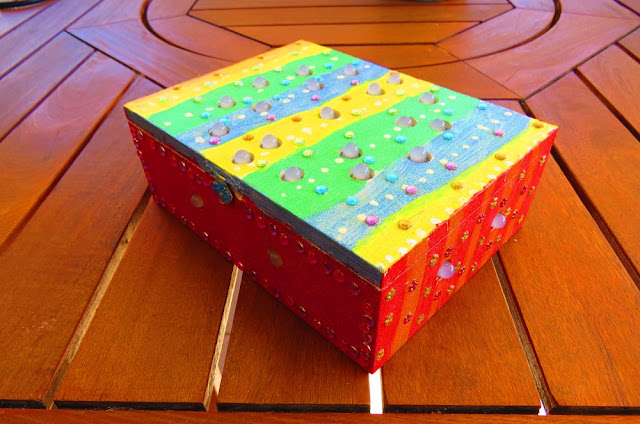
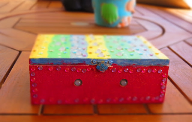
These pictures show the Light box after it has been drilled and painted. The LEDs have been inserted into their respective holes, and all wires + Arduino + breadboard are hidden within the box.


Concluding comments

Once you start writing LED animations for the NeoPixel Lightbox, it is very hard to stop. The colour combinations


If you like this page, please do me a favour and show your appreciation :

 
Visit my ArduinoBasics Google + page.
Follow me on Twitter by looking for ScottC @ArduinoBasics.
I can also be found on Pinterest and Instagram.
Have a look at my videos on my YouTube channel.


This project would not have been possible without OpenLab's collaborative effort.
Please visit their site for more cool projects.


However, if you do not have a google profile...
Feel free to share this page with your friends in any way you see fit.

Arduino LED Light Box

Description

Long straight lines of LED luminescence is nice, but sometimes you may want to light up something that has an unusual shape, or is not so linear. This is where the 12mm diffused flat digital RGB LED Pixels can come into play. This cool strand of 25 RGB LED pixels fit nicely into 12mm pre-drilled holes of any material you like.

This tutorial is dedicated to making a LED Light Box. I wanted the box to be equally as interesting during the day as it was at night. If you decide you make your own, feel free to be as creative as you want !! However, if you lack artistic acumen, you may need to source a minion or two.


Arduino Libraries and IDE

Before you start to hook up any components, upload the following sketch to the Arduino microcontroller. I am assuming that you already have the Arduino IDE installed on your computer. If not, the IDE can be downloaded from here.

The FastLED library is useful for simplifying the code for programming the RGB LED pixels. The latest "FastLED library" can be downloaded from here. I used FastLED library version 3.0.3 in this project.

If you have a different LED strip or your RGB LED pixels have a different chipset, make sure to change the relevant lines of code to accomodate your hardware. I would suggest you try out a few of the FastLED library examples before using the code below, so that you become more familiar with the library, and will be better equipped to make the necessary changes.

If you have a single strand of 25 RGB LED pixels with the WS8201 chipset, then you will not have to make any modification below.


ARDUINO CODE:

Arduino Code Description

The code above will generate a randomised raindrop pattern on the Arduino LED Light box, however I have written code for a few more LED animations. These animations were written specifically for this light-box setup. In other words, once you have hooked everything up, you will be able to upload these other LED animations to the Arduino board without any further modification to the hardware/wiring, and yet experience a totally different light effect. You can find the code for the other animation effects by clicking on the links below:

  1. Breathing effect
  2. Ripple effect
  3. Clock effect
  4. Rotation effect
  5. Sweep effect
  6. Spiral effect
  7. Lightning effect
  8. Paparazzi in the Rain effect

Hooking it up:

Power requirements

Each LED pixel can draw up to 60 milliamps at maximum brightness (white). ie. 20 mA for each colour (red, green and blue). Therefore you should not try to power the LED strand directly from the Arduino, because the strand will draw too much current and damage the microcontroller(and possibly your USB port too). The LED strand will therefore need to be powered by a separate power supply. The power supply must supply the correct voltage (5V DC) and must also be able to supply sufficient current (1.5A or greater per strand of 25 LEDs).

Excessive voltage will damage or destroy your LED pixel strand. The LEDs will only draw as much current as they need, however your power supply must provide at least 1.5A or greater for each strand. If you chain two strands together, you will need a 5V 3A power supply.

RGB LED pixel strand connection

There are 25 LED pixels per strand. Four of the wires at each end of the strand are terminated with a JST connector. The red wire is for power (VCC), blue wire for ground (GND), yellow wire is for Data, and green wire for Clock. A spare red wire (VCC) and a spare blue wire (GND) are attached to the ends of each strand for convenience, however, I did not use either. Please double check the colour of your wires... they may be different.

If you want to attach the LED strand to a breadboard, you can cut the JST connector off and use the LED pixel strand wires. Alternatively, if you would prefer to preserve the JST connector, you can simply insert jumper wires (or some male header pins) into the JST connector, and then plug them into the breadboard as required.

Each LED pixel is individually controllable using two pins on your Arduino. The strand is directional. i.e. There is an INPUT side and an OUTPUT side. The strand should be connected such that wires from the microcontroller are attached to the INPUT side of the first LED pixel. The arrows on each LED show the direction of data flow from INPUT to OUTPUT. The arrow on the first LED pixel should be pointing towards the second LED pixel, NOT towards the breadboard.

Other considerations

As a precaution, you should use a large capacitor across the + and - terminals of the power supply to prevent the initial onrush of current from damaging the RGB LED pixels. I used a 4700uF 16V Electrolytic capacitor for this purpose. According to Adafruit, a 1000uF 6.3V capacitor (or higher) will also do the trick. You may also want to consider a 330 ohm resistor between the Arduino Digital pin and the strand's DATA pin.

If you want to power the Arduino using the regulated 5V external power supply. Disconnect the USB cable from the Arduino, and then connect the positive terminal of the power supply to the 5V pin on the Arduino. Be warned however, that excess voltage at this pin could damage your Arduino, because the 5V regulator will be bypassed.
 
Providing the USB cable is NOT connected to the Arduino, it should now be safe to plug the power supply into the wall. This setup will allow you to power the RGB LED pixel strand and the Arduino using the same power supply.
 
WARNING: Never change any connections while the circuit is powered.

For more information about these RGB LED pixel strands, you may want to visit the Adafruit site. Adafruit was the source for most of these RGB LED pixel Strand precautions.


Fritzing diagram

The following diagram demonstrates how to connect the RGB LED pixel Strand to the Arduino and to the External 5V power supply.


This diagram was created using Fritzing


Connection Instructions

These instructions will help to guide you through the process of connecting your RGB LED pixel strand to the Arduino, and to the external power supply. The instructions assume that you will be powering the Arduino via a USB cable.


LightBox assembly

You will need to drill a 12mm hole into the craft timber box for each LED on the strand. It is worth taking the time to make accurate measurements before drilling the holes.
 
I made 12 holes for the outside circle pattern (12cm diameter), 6 holes for the inside circle pattern (8cm diameter), and a hole in the centre. I also made two holes at the front of the box, two on the left side, and two on the right side. I made one last hole at the back of the box for the 2.1mm DC power line socket.
 
Therefore you should have a total of 26 holes in the box. 25 of the holes are for the RGB LED pixel LEDs and one for the external power supply socket.

The lid of the box is about 19.5cm x 14.5cm long, which makes for a very tight squeeze. Probably too tight, because you have to account for the inner dimensions of the box. The inside of the box is used to house the Arduino, breadboard, the chipset side of the LEDs and cables/components. The inner dimensions of the box are 18cm x 13cm. Therefore, the housing for the LED chipset PCB (1.8cm x 2.5cm) prevented the box from closing. I used a Dremel to carve out the space required to close the lid.

Each LED is approximately 8cm apart on the strand, however, if you are really keen, you could cut the wires and extend them to any distance you require. But keep in mind that each LED is mounted on a small PCB (with a WS2801 chipset).You will therefore need to leave a minimum of 2cm between each 12mm hole to accomodate the size of the PCB+LED. If you plan carefully, you can probably squeeze a couple of LEDs within a distance of 1cm... but I would recommend that you give yourself a bit more room, because the PCBs are not square, and there is a good chance that you will have to start all over again.

In hindsight, I could have made the circle patterns a bit smaller, however I don't know if I could have packed these LEDs any closer. The diameter of the inner circle pattern must be at least 2cm smaller than the outer circle pattern. So I think "a bigger box" would have been the best option.

Once all of the holes have been drilled, paint and decorate the box to suit your style.

When the paint is dry, insert the LEDs into the drilled holes in number order.
You can see the end result below.


Project Pictures

These pictures show the Light box after it has been drilled and painted. The LEDs have been inserted into their respective holes, and all wires + Arduino + breadboard are hidden within the box.


Concluding comments

Once you start writing LED animations for the RGB LED pixel Lightbox, it is very hard to stop. The colour combinations


If you like this page, please do me a favour and show your appreciation :

 
Visit my ArduinoBasics Google + page.
Follow me on Twitter by looking for ScottC @ArduinoBasics.
I can also be found on Pinterest and Instagram.
Have a look at my videos on my YouTube channel.


This project would not have been possible without OpenLab's collaborative effort.
Please visit their site for more cool projects.


However, if you do not have a google profile...
Feel free to share this page with your friends in any way you see fit.

Yet another cool Pong with Arduino Uno

Everyone knows Pong, the first commercially successful arcade video game machine  originally release by Atari in 1972. In those years the game helped to establish the video game industry and nowadays is often used by makers to experiment with creating game consoles with Arduino.

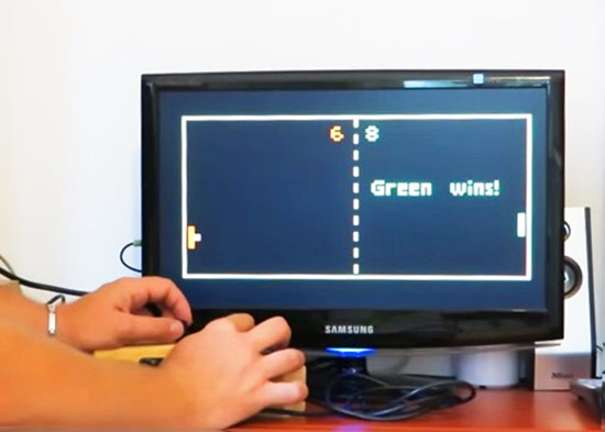
Roberto Melzi recently shared on the Arduino forum a new version of Pong made with Arduino Uno:

Thanks to the VGAx library done by Smaffer, based on the previous work done by Nick Gammon, I have done a little color game for an Arduino Uno working for a VGA monitor. See for details here:

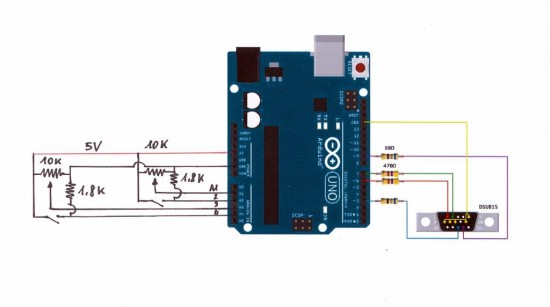
The target was to use an Arduino Uno board without special shields and supporting IC.
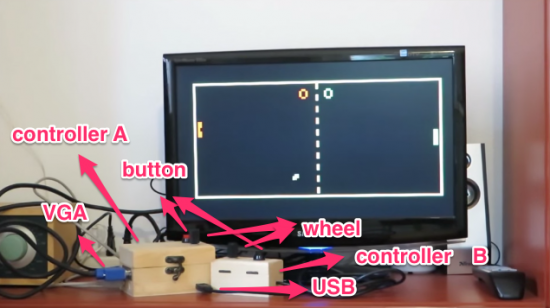
the fundamental components are a button, a potentiometer, few resistors and DSUB15 connector.

Tale a look at the video to see it in action:

Follow the step-by-step guide on Instructables to build one yourself.

Arduino Blog 24 Sep 21:11
arduino  featured  forum  library  pong  tutorial  uno  vga  video game  

Control your Arduino over the Internet using Blynk

Introduction

There are many ways of remotely-controlling your Arduino or compatible hardware over the Internet. Some are more complex than others, which can be a good thing or a bad thing depending on your level of expertise. Lately we’ve become more interested in this topic and have come across Blynk, which appeared to be a simple solution – and thus the topic of our review.

What is Blynk?

From their website: “Blynk is a Platform with iOS and Android apps to control Arduino, Raspberry Pi and the likes over the Internet. It’s a digital dashboard where you can build a graphic interface for your project by simply dragging and dropping widgets. 

It’s really simple to set everything up and you’ll start tinkering in less than 5 mins. Blynk is not tied to some specific board or shield. Instead, it’s supporting hardware of your choice. Whether your Arduino or Raspberry Pi is linked to the Internet over Wi-Fi, Ethernet or this new ESP8266 chip, Blynk will get you online and ready for the Internet Of Your Things.” Here is the original launch video:

Blynk started off as an idea, and raised initial funding through Kickstarter – which was successful and the system has now launched. Blynk comprises of an app on your smartphone (Android or iOS) inside which you can add widgets (controls) to send commands back to your development board (Arduino etc.).

For example, you can add a switch to turn a digital output on or off. Furthermore, data from sensors connected to the development board can be send back to the smartphone. The data passes through the Blynk Cloud server, or you can download and run your own server on your own hardware and infrastructure.

How much does it cost?

Right now (September 2015) the Blynk system is free. We downloaded the app and experimented without charge. We believe that over time there will be payment required for various functions, however you can try it out now to see if Blynk suits your needs then run with it later or experiment with other platforms.

Getting Started

Well enough talk, let’s try Blynk out. Our hardware is an Android smartphone (the awesome new Oppo R7+) for control, and a Freetronics EtherTen connected to our office modem/router:

You can also use other Arduino+Ethernet combinations, such as an Arduino Uno with an Ethernet shield. First you need to download the app for your phone – click here for the links. Then from the same page, download the Arduino library – and install it like you would any other Arduino library.

For our first example, we’ll use an LED connected to digital pin 7 (via a 560 ohm resistor) shown above. Now it’s time to set up the Blynk app. When you run the app for the first time, you need to sign in – so enter an email address and password:

Then click the “+” at the top-right of the display to create a new project, and you should see the following screen:

You can name your project, select the target hardware (Arduino Uno) – then click “E-mail” to send that auth token to yourself – you will need it in a moment. Then click “Create” to enter the main app design screen. Next, press “+” again to get the “Widget Box” menu as shown below, then press “Button”:

This will place a simple button on your screen:

Press the button to open its’ settings menu:

From this screen you can name your button, and also determine whether it will be “momentary” (i.e., only on when you press the button) – or operate as a switch (push on… push off…). Furthermore you need to select which physical Arduino pin the button will control – so press “PIN”, which brings up the scrolling menu as shown below:

We set ours to D7 then pressed “Continue”. Now the app is complete. Now head back to your computer, open the Arduino IDE, and load the “Arduino_Ethernet” sketch included with the library:

Then scroll down to line 30 and enter the auth key that was sent to you via email:

Save then upload the sketch to your Arduino. Now head back to your smartphone, and click the “Play” (looks like a triangle pointing right) button. After a moment the app will connect to the Blynk server… the Arduino will also be connected to the server – and you can press the button on the screen to control the LED.

And that’s it – remote control really is that easy. We’ve run through the process in the following short video:

Now what else can we control? How about some IKEA LED strips from our last article. Easy… that consisted of three digital outputs, with PWM. The app resembles the following:

… and watch the video below to see it in action:

Monitoring data from an Arduino via Blynk

Data can also travel in the other direction – from your Arduino over the Internet to your smartphone. At the time of writing this (September 2015) you can monitor the status of analogue and digital pins, and widgets can be added in the app to do just that. They can display the value returned from each ADC, which falls between zero and 1023 – and display the values in various forms – for example:

The bandwidth required for this is just under 2 K/s, as you can see from the top of the image above. You can see this in action through the video below:

Conclusion

We have only scratched the surface of what is possible with Blynk – which is an impressive, approachable and usable “Internet of Things” platform. Considering that you can get an inexpensive Android smartphone or tablet for under AU$50, the overall cost of using Blynk is excellent and well worth consideration, even just to test out the “Internet of Things” buzz yourself. So to get started head over to the Blynk site.

Tronixstuff 20 Sep 09:30