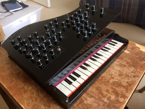
Electronic musical instruments are fun for Makers. With some cheap tools, know-how and passion, anyone can become a real synth geek. Just ask software developer Liam Lacey, who also happens to be a sound coder and freelance hacker. He recently won element14’s Open Source Music Tech design challenge for his Vintage Toy Synthesizer project — it’s an acoustic wooden toy piano converted into an open-source, standalone polyphonic digital synthesizer running on a BeagleBone Black and an Arduino Pro Mini.
Playing an instrument is about a lot more than just the sound you create – the way you play it; the physical feedback; and the overall feel and aesthetics of the instrument also play a big role in the overall experience, with these elements also helping to nurture inspiration, and can even affect your perception of the sound created.
Lacey developed the voice engine using the C++ audio DSP library Maximilian, and the keyboard mechanism uses homemade pressure sensors made out of Velostat. The instrument has 18 keys, with players able to also alter scales using the knobs on top of the mini piano’s lid.
Other dials are used to toggle dedicated waveform oscillators, various filters and onboard distortion effects, and there’s even vintage parameters for replicating old or broken analog synth voices. What’s neat is that the converted toy can also act as a MIDI controller to send velocity-sensitive note messages and polyphonic aftertouch to Logic Pro, Ableton Live and various music software programs.
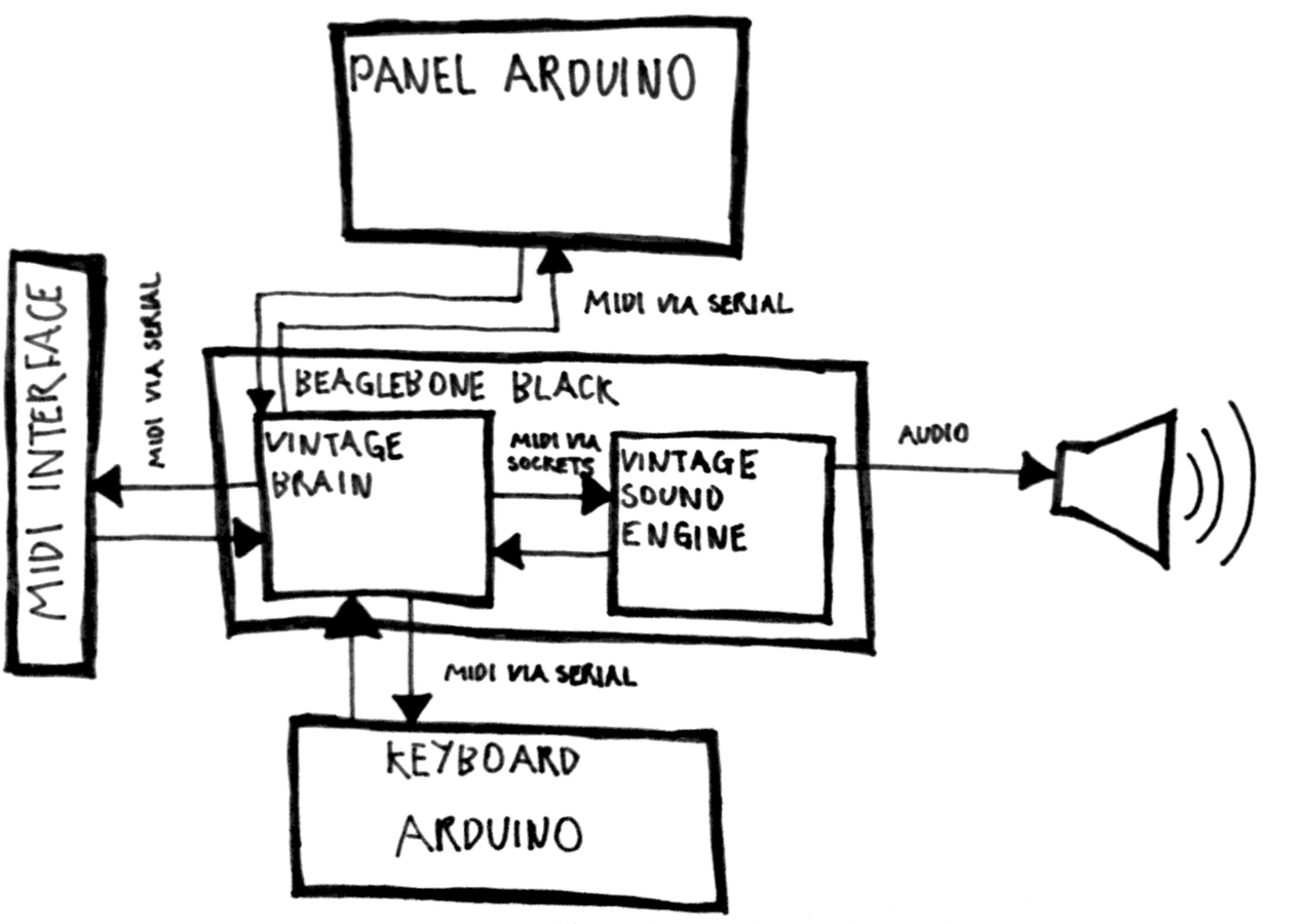
Here’s a diagram of the software architecture of the synth:
The project took three and a half months to bring to fruition, and let us just say, the final result is quite impressive! Check out the video below to learn more about its specs and explore the complete documentation on GitHub.
Hackaday reader [Jan Ostman] has been making microcontroller-based DIY synthesizers for quite a while now. Recently, he’s opened up the source for a lot of them so that you can play along at home. All of these virtual-analog synths and soundmakers can be realized on an Arduino or AVR ATmega328 if you happen to have one lying around.
Extra parts like a keyboard, some pushbuttons, or some potentiometer knobs to twiddle won’t hurt if you’d like to make something more permanent or more obviously playable, like [Jan] does. On the other hand, if you’d just like to get your feet wet, I’ve tweaked his code to be more immediately plug-and-play. The code is straightforward enough that it’s a good learning platform. So let’s take a quick tour through three drum machines and a string synth, each of which you can build on a breadboard in just a few minutes.
To install on an Arduino UNO, fetch the zip file from this GitHub repository, and move each subfolder to your Arduino sketch directory. You’re ready to play along.
Simple Drum Machines
[Jan] has two sample-playback~based drum machines that he’s published the code for: the dsp-D8 with straight-ahead drum samples and the dsp-L8 loaded with Latin percussion. They’re essentially the same code base, but with different samples, so we’ll treat them together.
Working through [Jan]’s code inspired me to write up a longer article on DDS playback, so if you want to brush up on the fundamentals, you can head over there. The short version is that you can change the pitch of playback of a sample by using a counter that’s much larger than the number of data points you’re going to play.
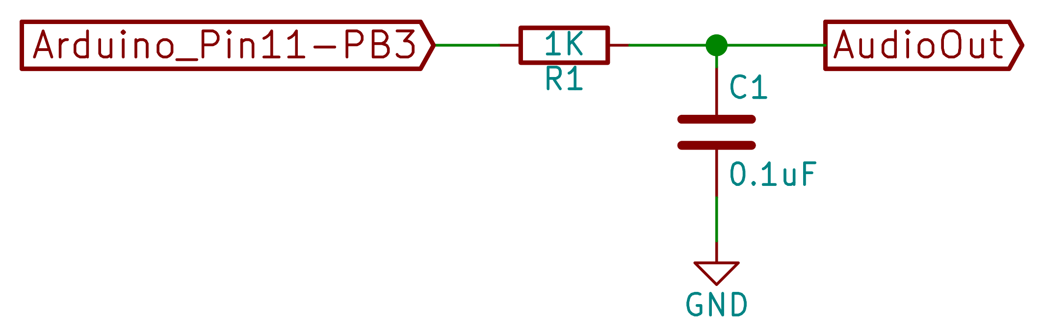
[Jan]’s drum machines all use the AVR’s hardware pulse-width modulation (PWM) peripherals to play the samples back out. You could use something fancier, but this gets the job done with just an optional resistor and capacitor filter on the output, bringing the total parts count to three: Arduino, 1 KOhm resistor, and a decent-sized (0.1 uF?) capacitor. An interrupt service routine (ISR) periodically loads a new sample value into the PWM register, and the AVR’s peripheral hardware takes care of the rest.
One nice touch is the use of a circular buffer that holds the playback sample values until the ISR is ready for them. In the case of the drum machines, there’s not much math for the CPU to do — it just combines the samples from all of the different simultaneous voices — but in his more complicated modules this buffer allows the CPU to occasionally take more time to calculate a sample value than it would otherwise have between updates. It buys [Jan]’s code some breathing room and still allows it to make the sample-playback schedule without glitching.
[Jan] adds individual pitch control for each sample, which is great for live playing or tweaking, and you can watch him use them in his two videos: one for the dsp-D8 and another for the dsp-L8. Wiring up so many knobs is a breadboard-salad, though, so I’ve gone through the code for you with a fine-toothed chainsaw, and hacked off [Jan]’s button-and-knob interface and replaced it with the Arduino’s built-in serial I/O.
To play my version of [Jan]’s drum machines, each sample is mapped to a key in the home row: “asdfjkl;”. If you’ve got a proper serial terminal program that transmits each keystroke in real-time, you’ll be tapping out rhythms at 9600 baud in no time. Note that the Arduino IDE’s built-in terminal only sends the keystroke after you hit “enter” — this makes playing in tempo very difficult. (I use screen /dev/ttyACM0 9600 or the terminal that’s built-in with Python’s pyserial library myself. What do Windows folks use for a real-time terminal?)
If you haven’t already, download this zip file, move each sub-folder to your Arduino sketch directory, and connect an amplified speaker either directly to your Arduino’s pin 11 and ground, or include an RC filter. It’ll only take a second before you’re playing. When you want the full version with all the knobs, head on over to [Jan]’s site.
O2 Minipops
[Jan]’s O2 Minipops machine mimics an old-school rhythm box: the Korg mini pops 7. Whether this primitive drum machine is horribly cheesy or divinely kitschy is in the ear of the beholder, but it’s a classic that has been used all over. [Jan]’s named his after an epic album Oxygene by Jean-Michel Jarre. You’ll hear them starting around 1:40 into the clip. Jarre famously used to press multiple buttons on the Minipops, making more complex drum patterns by playing more than one at a time.
The nice thing about having your own Minipops in firmware is that you can add the features you want to it. Instead of having to mash down multiple plastic buttons live on stage like poor Mr. Jarre, you can just tweak the firmware to suit. Need longer patterns? You’ve got the RAM. Emphasis? Swing? Tap tempo? It’s all just a matter of a few lines of code.
The sound playback code is just like the simpler drum machines above, so we won’t have to cover that again. The only real addition is the sequencer, but that’s where the real magic lies. After all, what’s a drum machine without some beats? Because there are eight possible drum sounds, each beat is a byte and so four bars of 4/4 time is just sixteen bytes stored in memory. I broke the data out into its own header file O2_data.h, so have a look there for the pre-programmed rhythms, and feel free to modify them to suit your own needs.
In order to make the O2 Minipops immediately playable, I stripped out the potentiometer code again (sorry [Jan]!) and passed off control over the serial port. The “user interface” has five controls. Press j and k to switch between patterns and f and d to speed up or slow down. (They’re under your first two fingers in the home row.) The space bar starts and stops the drum machine.
Try switching between the patterns on the fly with j and k — it’s a surprisingly fun way to create your own, slightly less cheesy, patterns. You need to download this code and give it a try. Trust me.
[Jan]’s Solina is a “virtual analog” in the sense that it builds up sawtooth waveforms in the microcontroller’s RAM and then outputs the corresponding voltage through PWM. And that’s a good start for a string synthesizer, because a filtered sawtooth waveform is a good first stab at the sound put out by a violin, for example.
Solina — the clone
The secret to the sound of the string section of an orchestra (and to string synthesizers that mimic it) is that it’s a combination of many different bowed instruments all playing at once. No matter how precise the players, they’re each slightly differently tuned, and none of the strings are resonating exactly in phase. The Solina mimics this by detuning each oscillator, naturally, and by moving them in and out of phase with each other. If you want to dig into the details of how exactly [Jan]’s Solina works, he explains it well in this blog post.
Again, I’ve converted it for direct-serial control, and you can control the envelope, detune, LFO speed, and modulation depth over the serial port. Press the spacebar once to simulate a keypress, and again to let go. Try the Solina with detune and pitch modulation around twenty, and play with the LFO rate and other parameters. That’s a lot of useful noise for just some sawtooth waves.
Keyboards and What’s Next
[Jan]’s builds are much more than what we’re demonstrating here, of course. His blog kicks off (in 2009!) with a project that essentially shoe-horns a PC into a keyboard enclosure, and the Solina and others get their own keys too. We’ve just presented the kernel of any such project — there’s a lot of labor-of-love left in wiring up all of the diodes necessary to do detection on a keyboard matrix, to say nothing of building enclosures, wiring up potentiometers, and making nice-looking front panels. But if you want to start down that path, you’ve at least got a good start.
[Jan]’s current project is the Minimo miniature monophonic synth that takes the Solina a step further and adds a lowpass filter with (digital) resonance to it. The resulting sounds are great, so we’re excited to see where [Jan] takes this one in the future.
Thanks again, [Jan], for opening the code up. And if any of you build something with this, be sure to post in the comments and let us all know. Since I started playing around with these, I’ve got the hankering to modularize the code up a bit and make it into something that’s even easier to adapt and modify. Maybe we’ll have to start up a Hackaday.io project — these little simple synths are just too much fun!
Direct-digital synthesis (DDS) is a sample-playback technique that is useful for adding a little bit of audio to your projects without additional hardware. Want your robot to say ouch when it bumps into a wall? Or to play a flute solo? Of course, you could just buy a cheap WAV playback shield or module and write all of the samples to an SD card. Then you wouldn’t have to know anything about how microcontrollers can produce pitched audio, and could just skip the rest of this column and get on with your life.
~45db signal to noise ratio from an Arduino
But that’s not the way we roll. We’re going to embed the audio data in the code, and play it back with absolutely minimal additional hardware. And we’ll also gain control of the process. If you want to play your samples faster or slower, or add a tremolo effect, you’re going to want to take things into your own hands. We’re going to show you how to take a single sample of data and play it back at any pitch you’d like. DDS, oversimplified, is a way to make these modifications in pitch possible even though you’re using a fixed-frequency clock.
The same techniques used here can turn your microcontroller into a cheap and cheerful function generator that’s good for under a hundred kilohertz using PWM, and much faster with a better analog output. Hackaday’s own [Bil Herd] has a nice video post about the hardware side of digital signal generation that makes a great companion to this one if you’d like to go that route. But we’ll be focusing here on audio, because it’s easier, hands-on, and fun.
We’ll start out with a sample of the audio that you’d like to play back — that is some data that corresponds to the voltage level measured by a microphone or something similar at regular points in time. To play the sample, all we’ll need to do is have the microcontroller output these voltages back at exactly the same speed. Let’s say that your “analog” output is via PWM, but it could easily be any other digital-to-analog converter (DAC) of your choosing. Each sample period, your code looks up a value and writes it out to the DAC. Done!
(In fact, other than reading the data from an SD card’s filesystem, and maybe having some on-board amplification, that’s about all those little WAV-player units are doing.)
Pitch Control
In the simplest example, the sample will play back at exactly the same pitch it was recorded if the sample playback rate equals the input sampling rate. You can make the pitch sound higher by playing back faster, and vice-versa. The obvious way to do this is to change the sample-playback clock. Every period you play back one the next sample, but you change the time between samples to give you the desired pitch. This works great for one sample, and if you have infinitely variable playback rates available.
Woof!
But let’s say that you want to take that sample of your dog barking and play Beethoven’s Fifth with it. You’re going to need multiple voices playing the sample back at different speeds to make the different pitches. Playing multiple pitches in this simplistic way, would require multiple sample-playback clocks.
Here’s where DDS comes in. The idea is that, given a sampled waveform, you can play nearly any frequency from a fixed clock by skipping or repeating points of the sample as necessary. Doing this efficiently, and with minimal added distortion, is the trick to DDS. DDS has its limits, but they’re mostly due to the processor you’re using. You can buy radio-frequency DDS chips these days that output very clean sampled sine waves up to hundreds of megahertz with amazing frequency stability, so you know the method is sound.
Example
Let’s make things concrete with a simplistic example. Say we have a sample of a single cycle of a waveform that’s 256 bytes long, and each 8-bit byte corresponds to a single measured voltage at a point in time. If we play this sample back at ten microseconds per sample we’ll get a pitch of 1 / (10e-06 * 256) = 390.625 Hz, around the “G” in the middle of a piano.
Imagine that our playback clock can’t go any faster, but we’d nonetheless like to play the “A” that’s just a little bit higher in pitch, at 440 Hz. We’d be able to play the “A” if we had only sampled 227 bytes of data in the first place: 1 / (10e-06 * 227) = 440.53, but it’s a little bit late to be thinking of that now. On the other hand, if we just ignored 29 of the samples, we’d be there. The same logic works for playing lower notes, but in reverse. If some samples were played twice, or even more times, you could slow down the repetition rate of the cycle arbitrarily.
In the skipping-samples case, you could just chop off the last 29 samples, but that would pretty seriously distort your waveform. You could imagine spreading the 29 samples throughout the 256 and deleting them that way, and that would work better. DDS takes this one step further by removing different, evenly spaced samples with each cycle through the sampled waveform. And it does it all through some simple math.
The crux is the accumulator. We’ll embed the 256 samples in a larger space — that is we’ll create a new counter with many more steps so that each step in our sample corresponds to many numbers in our larger counter, the accumulator. In my example code below, each of the 256 steps gets 256 counts. So to advance one sample per period, we need to add 256 to the larger counter. To go faster, you add more than 256 each period, and to go slower, add less. That’s all there is to it, except for implementation details.
In the graph here, because I can’t draw 1,024 tick marks, we have 72 steps in the accumulator (the green outer ring) and twelve samples (inner, blue). Each sample corresponds to six steps in the accumulator. We’re advancing the accumulator four steps per period (the red lines) and you can see how the first sample gets played twice, then the next sample played only once, etc. In the end, the sample is played slower than if you took one sample per time period. If you take more than six steps in the increment, some samples will get skipped, and the waveform will play faster.
Implementation and Build
So let’s code this up and flash it into an Arduino for testing. The code is up at GitHub for you to follow along. We’ll go through three demos: a basic implementation that works, a refined version that works a little better, and finally a goofy version that plays back single samples of dogs barking.
Filter “circuit”
In overview, we’ll be producing the analog output waveforms using filtered PWM, and using the hardware-level PWM control in the AVR chip to do it. Briefly, there’s a timer that counts from 0 to 255 repeatedly, and turns on a pin at the start and turns it off at a specified top value along the way. This lets us create a fast PWM signal with minimal CPU overhead, and it uses a timer.
Still some jaggies left. Could use better filter.
We’ll use another timer that fires off periodically and runs some code, called an interrupt service routine (ISR), that loads the current sample into the PWM register. All of our DDS code will live in this ISR, so that’s all we’ll focus on.
If this is your first time working directly with the timer/counters on a microcontroller, you’ll find some configuration code that you don’t really have to worry about. All you need to know is that it sets up two timers: one running as fast as possible and controlling a PWM pin for audio output, and another running so that a particular chunk of code is called consistently, 24,000 times per second in this example.
So without further ado, here’s the ISR:
struct DDS {
    uint16_t increment;
    uint16_t position;
    uint16_t accumulator;
    const int8_t* sample;   /* pointer to beginning of sample in memory */
};
volatile struct DDS voices[NUM_VOICES];

ISR(TIMER1_COMPA_vect) {
    int16_t total = 0;

    for (uint8_t i = 0; i < NUM_VOICES; i++) {
        total += (int8_t) pgm_read_byte_near(voices[i].sample + voices[i].position);

        /* Take an increment step */
        voices[i].accumulator += voices[i].increment;
        voices[i].position += voices[i].accumulator / ACCUMULATOR_STEPS;
        voices[i].accumulator = voices[i].accumulator % ACCUMULATOR_STEPS;
        voices[i].position = voices[i].position % SAMPLE_LENGTH;
    }

    total = total / NUM_VOICES;
    OCR2A = total + 128; // add in offset to make it 0-255 rather than -128 to 127
}
The first thing the code does is to define a (global) variable that will hold the state of each voice for as many voices as we want, defined by NUM_VOICES. Each voice has an increment which determines how many steps to take in the accumulator per sample output. The position keeps track of exactly which of the 256 samples in our waveform data is currently playing, and the accumulator keeps track of the rest. Here, we’re also allowing for each voice to play back a different waveform table from memory, so the code needs to keep track of the address where each sample begins. Changing which sample gets played back is as simple as pointing this variable to a different memory location, as we’ll see later. For concreteness, you can imagine this sample memory to contain the points in a sine wave, but in practice any repetitive waveform will do.
So let’s dive into the ISR, and the meat of the routine. Each update cycle, the sum of the output on the different voices is calculated in total. For each voice, the current sample is read from memory, added to the total and then incremented to the next step. Here we get to see how the accumulator works. The increment variable is added to the accumulator. When the accumulator is larger than the number of steps per sample, the position variable gets moved along. Next, the accumulator is shrunk back down to just the remainder of the un-accounted-for values using the modulo operator, and the sample position is wrapped around if necessary with another modulo.
Division?? Modulo??
If you’ve worked with microcontrollers before, alarm bells may be going off in your head right now. The AVR doesn’t have a built-in division routine, so that could take a lot of CPU power. And the modulo operator is even worse. That is, unless the divisor or modulo are powers of two. In those cases, the division is the same as shifting the binary number to the right by the number of bits in the power of two.
A similar operation makes the modulo tolerable. If, for instance, you want a number to be modulo eight, you can simply drop all of the binary bits that correspond to values eight and higher. So, x % 8 can be implemented as x & 0b00000111 where this logical-ANDing just keeps the least-significant three bits. If you’re not in tune with your inner bit-flipper, this can be viewed as a detail — but just know that division and modulo aren’t necessarily bad news if your compiler knows how to implement them efficiently when you choose powers of two for the divisors.
And that gets us to the end of the routine. The sample values were added together, so now they need dividing by the number of voices and centering around the mid-point to fit inside the 8-bit range that the PWM output register requires. As soon as this value is loaded into memory, the PWM hardware will take care of outputting the right waveform on its next cycle.
Refinements
The ISR above is already fairly streamlined. It’s avoided the use of any if statements that would otherwise slow it down. But it turns out we can do better, and this optimized form is often the way you’ll see DDS presented. Remember, we’re running this ISR (in this example) 24,000 times per second — any speedup inside the ISR makes a big difference in overall CPU usage.
The first thing we’ll do is make sure that we have only 256 samples. That way, we can get rid of the line where we limit the sample index to being within the correct range simply by using an 8-bit variable for the sample value. As long as the number of bits in the sample index matches the length of the sample, it will roll over automatically.
We can use the same logic to merge the sample and accumulator variables above into a single variable. If we have an 8-bit sample and an 8-bit accumulator, we combine them into a 16-bit accumulator where the top eight bits correspond to the sample location.
struct DDS {
    uint16_t increment;
    uint16_t accumulator;
    const int8_t* sample;   /* pointer to beginning of sample in memory */
};
volatile struct DDS voices[NUM_VOICES];

ISR(TIMER1_COMPA_vect) {
    int16_t total = 0;

    for (uint8_t i = 0; i < NUM_VOICES; i++) { total += (int8_t) pgm_read_byte_near(voices[i].sample + (voices[i].accumulator >> 8));
        voices[i].accumulator += voices[i].increment;
    }
    total = total / NUM_VOICES;
    OCR2A = total + 128; // add in offset to make it 0-255 rather than -128 to 127
}
You can see that we’ve dropped the position value from the DDS structure entirely, and that the ISR is significantly streamlined in terms of lines of code. (It actually runs about 10% faster too.) Where previously we played the sample at sample + position, we are now playing the sample at sample + (accumulator >> 8). This means that the effective position value will only advance once every 256 steps of the increment — the high eight bits only change once all of the low 256 steps have been stepped through.
None of this is strange if you think about it in base 10, by the way. You’re used to counting up to 99 before the third digit flips over to 100. Here, we’re just using the most-significant bits to represent the sample step, and the number of least-significant bits determines how many increments we need to make before a step is taken. This method is essentially treating the 16-bit accumulator as a fixed-point 8.8 position value, if that helps clear things up. (If not, I’m definitely going to write something on fixed-point math in the future.) But that’s the gist of it.
This is the most efficient way that I know to implement a DDS routine on a processor with no division, but that’s capable of doing bit-shifts fairly quickly. It’s certainly the classic way. The catch is that both the number of samples has to be a power of two, the number of steps per sample has to be a power of two, and the sum of both of them has to fit inside some standard variable type. In practice, this often means 8-bit samples with 8-bit steps or 16-bit samples with 16-bit steps for most machines. On the other hand, if you only have a 7-bit sample, you can just use nine bits for the increments.
Goofing Around: Barking Dogs
As a final example, I’d like to run through the same thing again but for a simple sample-playback case. In the demos above we played repeating waveforms that continually looped around on themselves. Now, we’d like to play a sample once and quit. Which also brings us to the issue of starting and stopping the playback. Let’s see how that works in this new ISR.
struct Bark {
    uint16_t increment = ACCUMULATOR_STEPS;
    uint16_t position = 0;
    uint16_t accumulator = 0;
};
volatile struct Bark bark[NUM_BARKERS];

const uint16_t bark_max = sizeof(WAV_bark);

ISR(TIMER1_COMPA_vect) {
    int16_t total = 0;

    for (uint8_t i = 0; i < NUM_BARKERS; i++) {
        total += (int8_t)pgm_read_byte_near(WAV_bark + bark[i].position);

        if (bark[i].position < bark_max){    /* playing */
            bark[i].accumulator += bark[i].increment;
            bark[i].position += bark[i].accumulator / ACCUMULATOR_STEPS;
            bark[i].accumulator = bark[i].accumulator % ACCUMULATOR_STEPS;
        } else {  /*  done playing, reset and wait  */
            bark[i].position = 0;
            bark[i].increment = 0;
        }
    }
    total = total / NUM_BARKERS;
    OCR2A = total + 128; // add in offset to make it 0-255 rather than -128 to 127
}
The code here is broadly similar to the other two. Here, the wavetable of dogs barking just happened to be 3,040 samples long, but since we’re playing the sample once through and not looping around, it doesn’t matter so much. As long as the number of steps per position (ACCUMULATOR_STEPS) is a power of two, the division and modulo will work out fine. (For fun, change ACCUMULATOR_STEPS to 255 from 256 and you’ll see that the whole thing comes crawling to a stop.)
The only difference here is that there’s an if() statement checking whether we’ve finished playing the waveform, and we explicitly set the increment to zero when we’re done playing the sample. The first step in the wavetable is a zero, so not incrementing is the same as being silent. That way, our calling code only needs to set the increment value to something non-zero and the sample will start playing.
If you haven’t already, you should at least load this code up and look through the main body to see how it works in terms of starting and stopping, playing notes in tune, and etcetera. There’s also some thought that went into making the “synthesizer” waveforms in the first examples, and into coding up sampled waveforms for use with simple DDS routines like this. If you’d like to start off with a sample of yourself saying “Hackaday” and running that in your code, you’ll find everything you need in the wave_file_generation folder, written in Python. Hassle me in the comments if you get stuck anywhere.
Conclusion
DDS is a powerful tool. Indeed, it’s more powerful than we’ve even shown here. You can run this exact routine at up to 44 kHz, just like your CD player, but of course at an 8-bit sample depth instead of 16. You’ll have to settle for two or three voices instead of four because that speed is really taxing the poor little AVR inside an Uno. With a faster CPU, you can not only get out CD-quality audio, but you can do some real-time signal processing on it as well.
And don’t even get me started on what chips like the Analog Devices high-speed DDS chips that can be had on eBay for just a few dollars. They’re doing the exact same thing, for a sinewave, at very high speed and frequency accuracy. They’re a far cry from implementing DDS in software on an Arduino to make dogs bark, but the principle is the same.
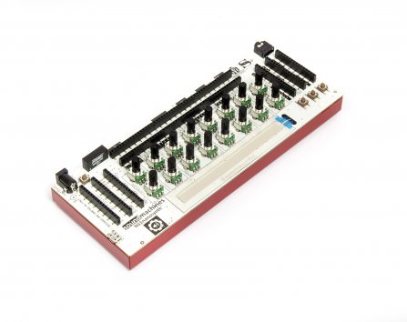
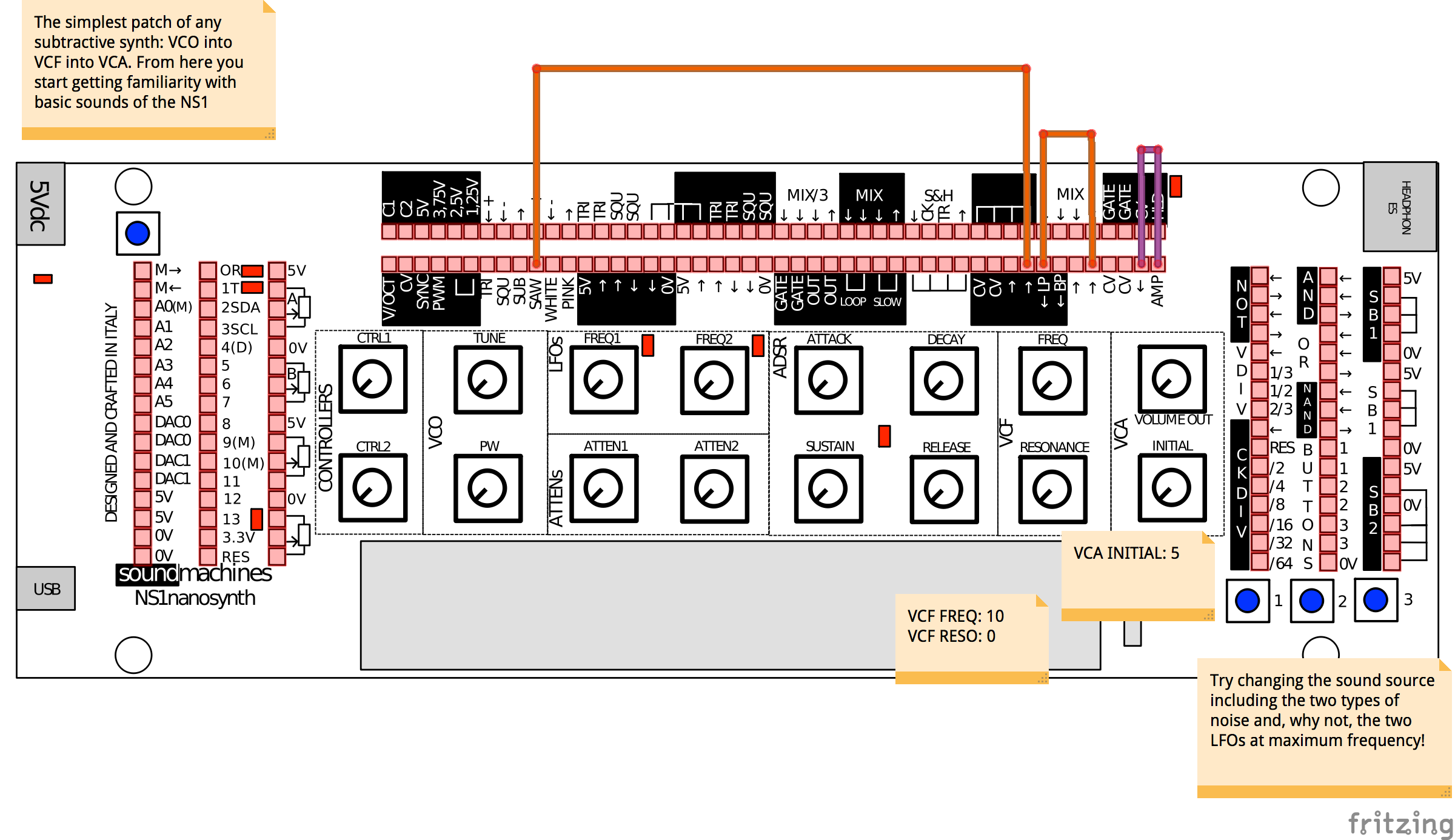
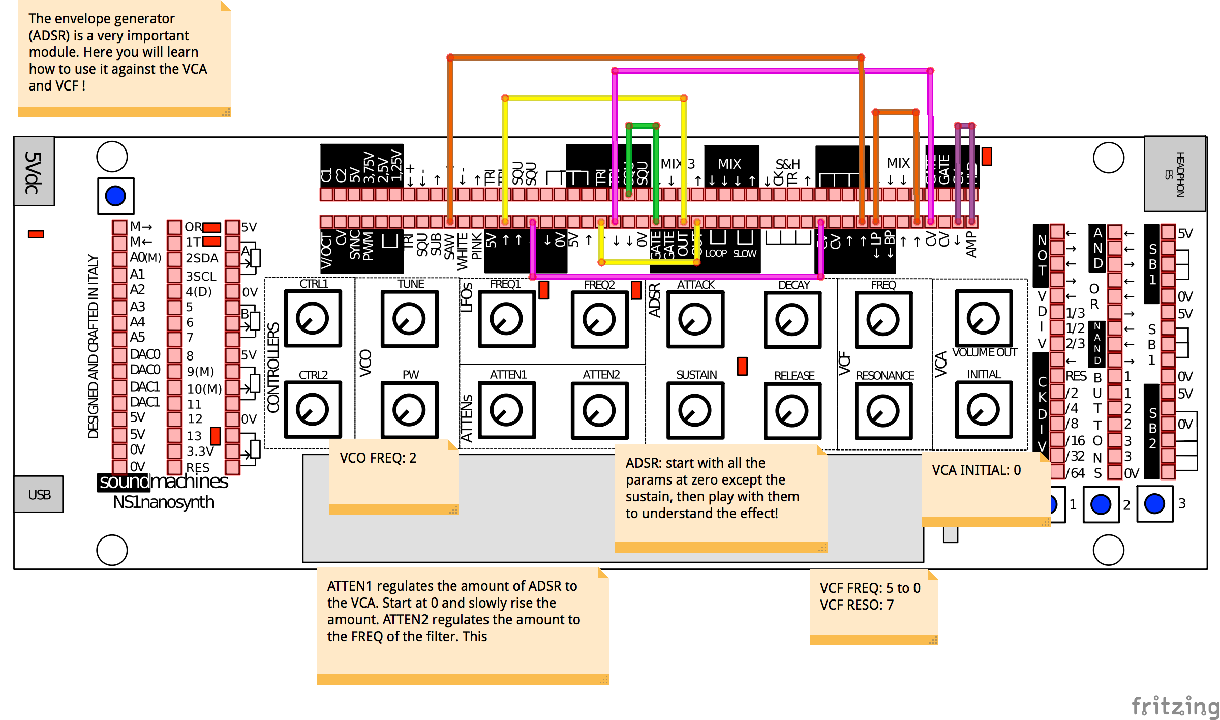
Personally, it was one of my first steps into modular synthesizers. Nice sounds, easy approach. Peter Kirn is perfectly picturing this amazing compromise here!
Synths: they’re fun to tweak and play. Modulars: they’re fun to patch. Arduinos: they’re fun to hack. Small things: they’re fun to carry around.
But how to track patches? How to share sounds with friends? I was playing mainly with my son, and managed to print out a paper sketch depicting all the different pinout of the synth. I wasn’t satisfied with that, I needed more!
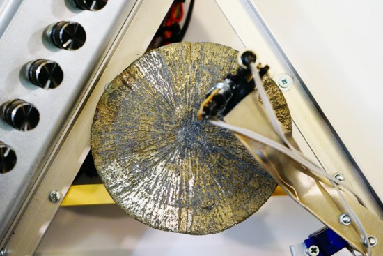
There’s a mineral called pyrite with a interesting nickname, fool’s gold, because it has a superficial resemblance to gold and it’s by far the most frequently mineral mistaken for gold. Even if it’s pretty abundant, there’s a rare form of pyrite which is crystallised in radial shape (as unusual disc spherulites), taking the shape of a disc. The amazing fact is that the only deposit where pyrites of such morphology are found is in Illinois (USA) and the discs are dated around 300 million years ago!
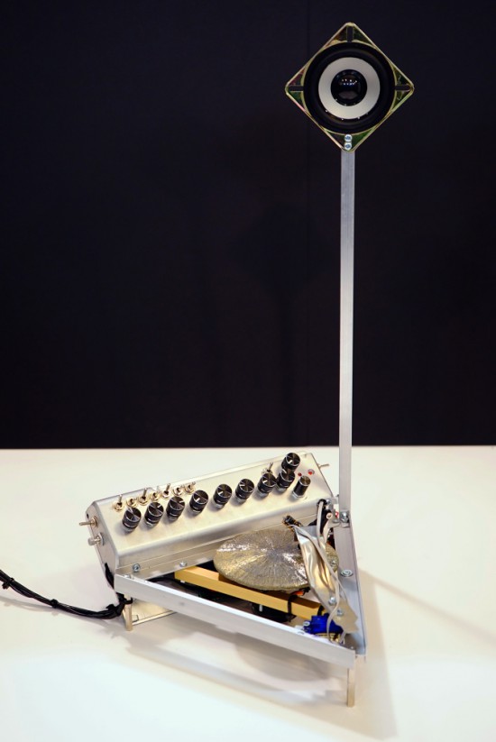
Dmitry Morozov (aka ::vtol::), a media artist living in Moscow, had the chance to use a pyrite disc and created Ra, a sound object / synthesizer running on Arduino Nano. Ra uses laser for scanning the irregularities of the surface of the disc and further transforms this data to produce sound:
This project originated as a result of an interesting set of circumstances – a pyrite disc was given to me as a gift by a mineral seller in Boulder city (USA). Upon hearing about my works, she asked to do something with such crystal, and refused to take payment for getting it. In the same period, I was reading articles on various ways of archiving and preservation of sounds from the first, historical sources of the recorded sound – wax discs and other fragile carriers. All technologies were based on the usage of lasers. Inspired by these projects, I set out to create a self-made laser sound reader which would be able to produce sound from various uneven surfaces, using minimal resources to achive it. Thus emerged the idea to construct an instrument using the pyrite disc and a self-made laser sound reader.
The production of the object was possible thanks to the commission of the Sound Museum in St.-Petersburg which now has Ra in its collection.
Everybody needs an external USB drive at some time or another. If you’re looking for something with the nerd cred you so desperately need, build a 5 1/4″ half height external drive. That’s a mod to an old Quantum Bigfoot drive, and also serves as a pretty good teardown video for this piece of old tech.
The Woxun KG-UV2D and KG-UV3D are pretty good radios, but a lot of amateur radio operators have found these little handheld radios eventually wear out. The faulty part is always a 24C64 Flash chip, and [Shane] is here to show you the repair.
Last year there was a hackathon to build a breast pump that doesn’t suck in both the literal and figurative sense. The winner of the hackathon created a compression-based pump that is completely different from the traditional suction-based mechanism. Now they’re ready for clinical trials, and that means money. A lot of money. For that, they’re turning to Kickstarter.
What you really need is head mounted controls for Battlefield 4. According to [outgoingbot] it’s a hacked Dualshock 4 controller taped to a bike helmet. The helmet-mounted controller has a few leads going to another Dualshock 4 controller with analog sticks. This video starts off by showing the setup.
The HackFFM hackerspace in Frankfurt finally got their CO2 laser up and running, and the folks there were looking for something to engrave. They realized the labels on IC packages are commonly laser engraved, so they made a DIP-sized Arduino. The pins are labelled just as they would be on an Arduino, and a few SMD components dead bugged onto the pins provide all the required circuitry. Video here.
The Raspberry Pi is now a form factor, with the HummingBoard, a Freescale i.MX6-powered clone, being released soon. There’s another form factor compatible platform out there, the Banana Pi, and you can actually buy it now. It’s an ARM A20 dual core running at 1GHz, Gig of RAM, and Gigabit Ethernet for about $60. That SATA port is really, really cool, too.
[Richard] has been working on a solar-powered sun jar this winter and now he’s done. The design uses two small solar panels to charge up two 500F (!) supercapacitors. There’s a very cool and very small supercap charging circuit in there, and unless this thing is placed in a very dark closet, it’ll probably keep running forever. Or until something breaks.
Here’s something awesome for the synth heads out there: it’s an analog modeling synthesizer currently on Indiegogo. Three DCOs, 18dB lowpass filter, 2 envelopes and an LFO, for all that classic Moog, Oberheim, and Roland goodness. It’s also pretty cheap at $120 USD. We really don’t get enough synth and musical builds here at Hackaday, so if you’re working on something, send it in.
A glass-based PCB? Sure. Here’s [Masataka Joei] put gold and silver on a piece of glass, masked off a few decorative shapes, and sandblasted the excess electrum away. [Masataka] is using it for jewelery, but the mind races once you realize you could solder stuff to it.
Music lovers will often tell you that Roland's TR-808 gave birth to modern music. Acid house, rap, techno and other genres owe some of their original (and even current) sounds to that synthetic beat. Moritz Simon Geist appreciates the effort, but has built a solution for those who think the drum machine is a little too perfect: his MR-808 installation has robot limbs playing all the equivalent real-world instruments, right down to the cowbell. A laptop musician at the helm sends MIDI input to an Arduino controller that then triggers the robot's instrument motors and matching lights. The effect is a unique mix of flawless cues with imprecise, almost organic sounds -- imagine 808 State or Kanye West replacing each and every machine with a live band and you've got the idea. Although the sheer size of the MR-808 sadly nixes chances you'll ever see one at the local nightclub, it could give any of Geist's recorded music one of the more distinct vibes we've heard.
Judging from the video (found after the break) the Nebulophone is one of the best sounding DIY synthesizers we’ve seen. Especially when you consider the simplicity of the hardware design. It uses an AVR chip and an OpAmp. The rest of the parts are just a few handfuls of inexpensive components.
An ATmega328 drives the device, which is the chip often used in the Arduino Duemilanove. The keyboard is a set of traces hooked to the microcontroller. These are tinned pads on the kit PCB, but the DIY version simply uses some adhesive copper foil with a jumper wire soldered to it. The keys are played with a probe that makes the electrical connection, a common practice on these stylophone type designs. Chances are you have everything on hand to make this happen so keep it in mind for that next cold winter weekend that’s making everyone a bit stir crazy.
This instructable shows you how to create a very simple Arduino-based sequencer with nice features:
Multiple synthesizer projects has been done for the Arduino, but few has been able to utilize the full power of the Arduino processor. DZL from GeekPhysical wrote a 4 voice wavetable synthesizer that is one of more advanced software based synths for the Arduino. It has wavetables included (sine, saw, square and triangle) and envelopes to create beats.
Implementation instructions can be found here, while the Arduino code can be obtained from GitHub.