A Miniature Radio Telescope in Every Backyard
You probably wouldn’t expect to see somebody making astronomical observations during a cloudy day in the center of a dense urban area, but that’s exactly what was happening at the recent 2019 Philadelphia Mini Maker Faire. Professor James Aguirre of the University of Pennsylvania was there demonstrating the particularly compact Mini Radio Telescope (MRT) project built around an old DirecTV satellite dish and a smattering of low-cost components, giving visitors a view of the sky in a way most had never seen before.
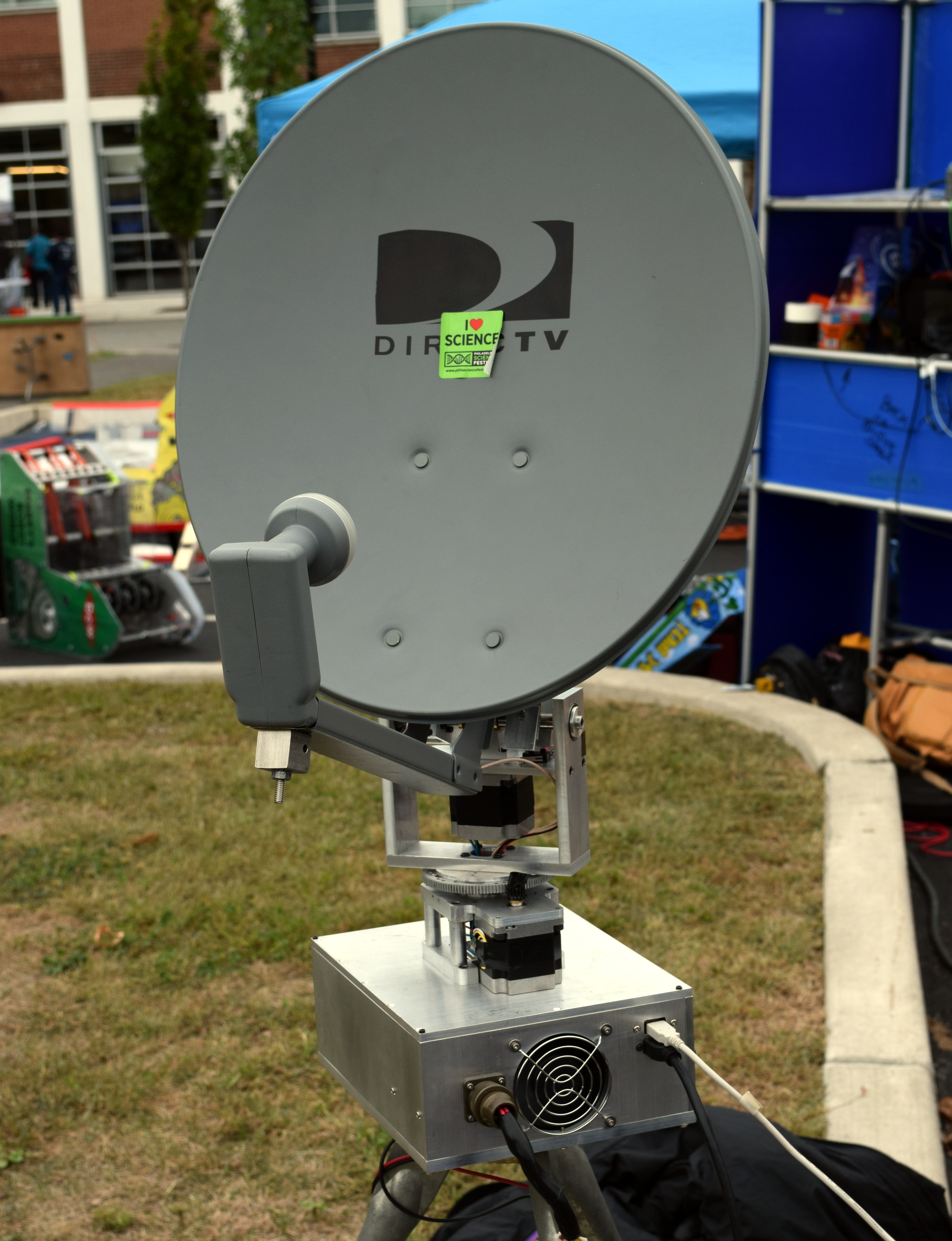 Thanks to the project’s extensive online documentation, anyone with a spare satellite dish and a couple hundred dollars in support hardware can build their very own personal radio telescope that’s capable of observing objects in the sky no matter what the time of day or weather conditions are. Even if you’re not interested in peering into deep space from the comfort of your own home, the MRT offers a framework for building an automatic pan-and-tilt directional antenna platform that could be used for picking up signals from orbiting satellites.
With the slow collapse of satellite television in the United States these dishes are often free for the taking, and a fairly common sight on the sidewalk come garbage day. Perhaps there’s even one (or three) sitting on your own roof as you read this, waiting for a new lease on life in the Netflix Era.
Whether it’s to satisfy your own curiosity or because you want to follow in Professor Aguirre’s footsteps and use it as a tool for STEM outreach, projects like MRT make it easier than ever to build a functional DIY radio telescope.
Point and Shoot
The MRT, and really any radio telescope project like this, is essentially made up of two separate systems: one that provides the motorized aiming of the dish, and the receiver that actually captures the signals. Either system could work independently of the other, but when combined with the appropriate software “glue”, they allow the user to map the sky in radio frequencies.
Obviously, the electronics and mechanical components required to pan an antenna across the sky aren’t terribly complex. If you wanted to keep things really simple and were content with moving in a single axis, you could even do it with a “barn door” tracker. What’s really kicked off the recent explosion of DIY radio telescopes is the RTL-SDR project and the era of low-cost Software Defined Radios (SDRs) it’s inspired.
 Unsurprisingly, the MRT also uses an RTL-SDR receiver for processing signals from the Low-Noise Block (LNB) in the dish. Professor Aguirre says that since they are still using the stock DirecTV LNB, the telescope is fairly limited in what it can actually “see”. But it’s good enough to image the sun or pick up satellites in orbit, which is sufficient for the purposes of demonstrating the basic operating principles of a radio telescope.
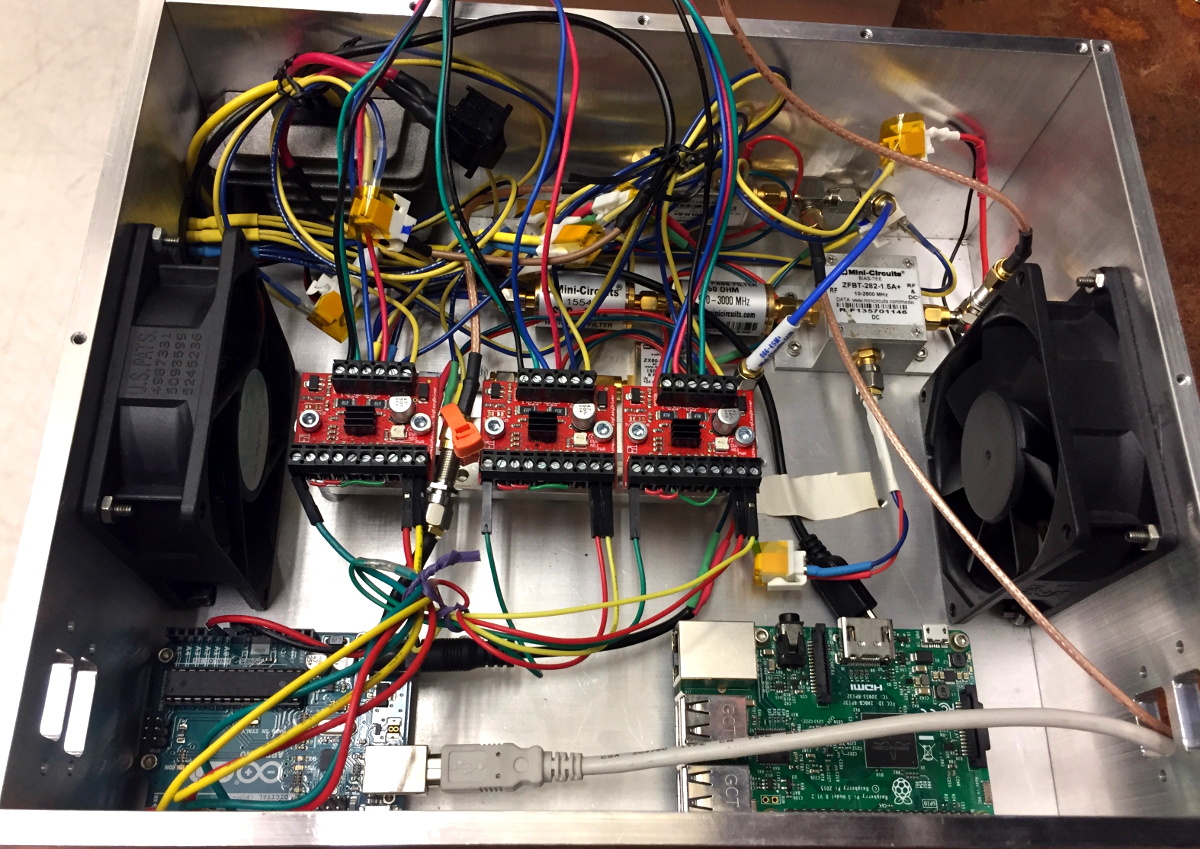
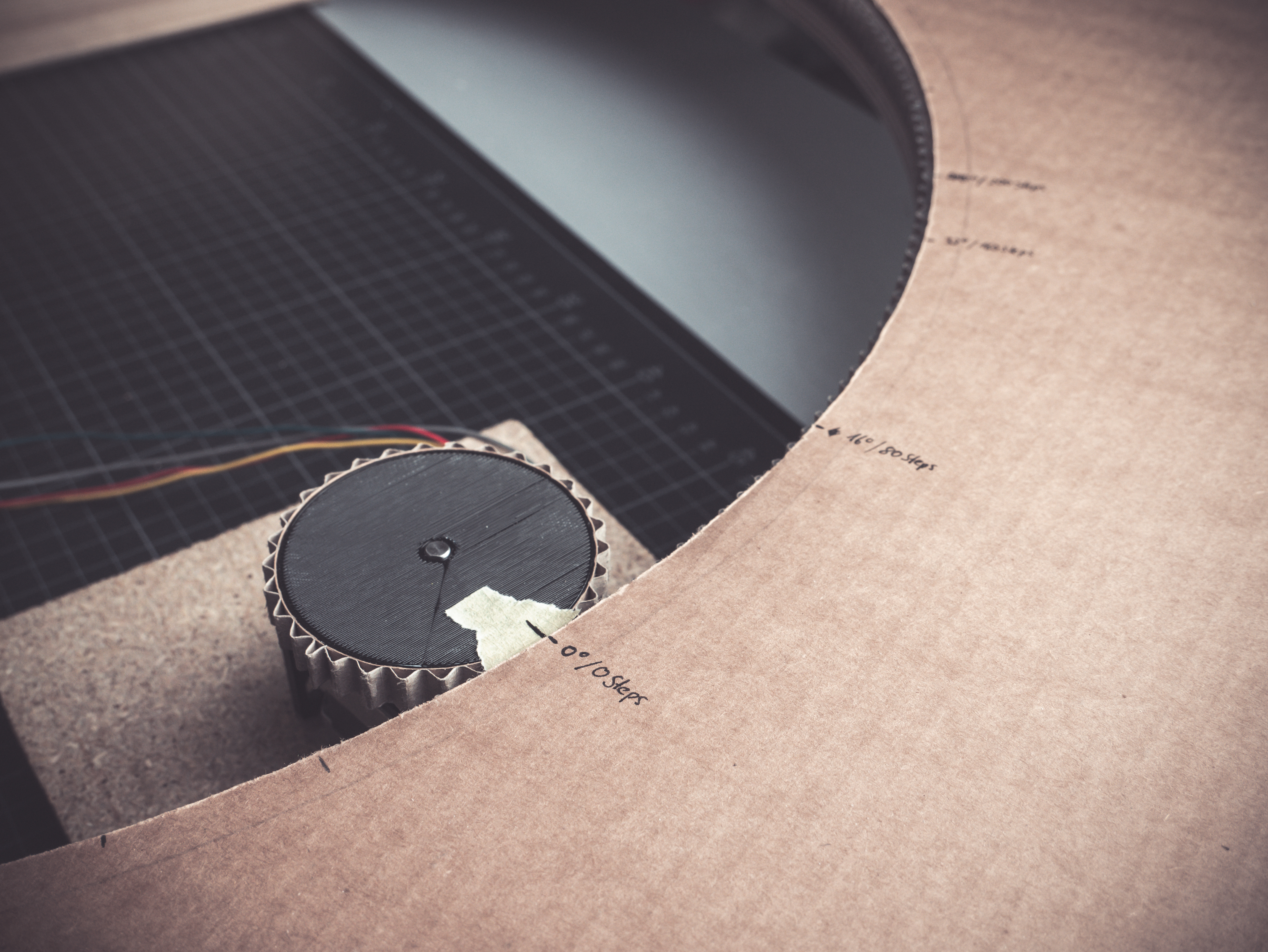
To move the satellite dish, the MRT is using an Arduino connected to a trio of Big Easy Drivers from Sparkfun. These are in turn connected to the stepper motors in the antenna mount, which are sufficiently geared so they can move the dish around without the need for a counterweight. This makes it an excellent candidate for enclosure inside a dome, which would allow for all-weather observations.
Both the RTL-SDR receiver and the Arduino are connected to a Raspberry Pi, which runs the software for the telescope and provides the interface for the user. The MRT GitHub repository contains all of the various tools and programs created for the project, mostly written in Python, which should provide a useful reference even if you’re not interested in duplicating the telescope’s overall design.
Wandering Through the Sky
When we visited Professor Aguirre, he was attempting to use the MRT to find the Sun. You’d think that a simple enough task in the middle of the afternoon, but thanks to an unbroken layer of steel-gray clouds hanging low in the October sky, Sol was absolutely nowhere to be found with our meager human senses.

As the dish made its slow robotic pans across the sky, we spoke with the Professor about the telescope and the various revisions it went through over the years. Eventually the display lit up, showing a representation of an unusually strong signal, clearly the MRT was hearing something out there. After brief scrutiny, the Professor announced that we hadn’t found the sun; instead, the telescope most likely crossed paths with a geostationary satellite.
It was this raconteur style of discovery that kept visitors to the Mini Radio Telescope enthralled. Nobody expected this hacked together contraption of consumer-grade hardware to discover a new exoplanet or help solve some long-pondered mystery of the cosmos while sitting in a Philadelphia parking lot.
But it was more than capable of pointing out objects tens of thousands of kilometers away while our own eyes couldn’t even figure out where the Sun was. It reaffirmed in a very real way that something was out there, and students both young and old couldn’t help but be fascinated by it.

 In a project, repetitive tasks that break the flow of development work are incredibly tiresome and even simple automation can make a world of difference. [Simon Merrett] ran into exactly this while testing different stepper motors in a strain-wave gear project. The system that drives the motor accepts G-Code, but he got fed up with the overhead needed just to make a stepper rotate for a bit on demand. His solution? A

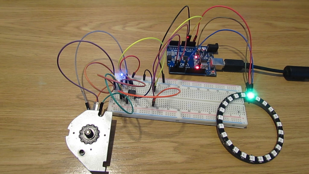
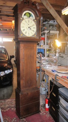 He starts off by building a custom electro-mechanical clock movement, and since he’s planning as he progresses, meccano, breadboard and jumper wires were the way to go. Hot glue helps preserve sanity by keeping all the jumper wires in place. To interface with all of the peripherals in the clock, he decided to use a bank of shift registers driven from a regular Arduino Uno. The more expensive DS3231 RTC module ensures better accuracy compared to the cheaper DS1307 or similar clones. A bank of RGB LEDs acts as an annunciator panel inside the clock to help provide various status indications. The mechanical movement itself went through several iterations to get the time display working with a smooth movement of the hands. Besides displaying time, [David] also added a moon phase indicator dial. A five-rod chime is struck using a stepper motor driven cam and a separate solenoid is used to pull and release three chime hammers simultaneously to generate the loud gong sounds.