We love to see projects undertaken for the pure joy of building something new, but to be honest those builds are a dime a dozen around here. So when we see a great build that also aims to enhance productivity and push an entrepreneurial effort along, like this automated small parts counter, we sit up and take notice.
The necessity that birthed this invention is [Ryan Bates’] business of building DIY arcade game kits. The mini consoles seen in the video below are pretty slick, but kitting the nuts, bolts, spacers, and other bits together to ship out orders was an exercise in tedium. Sure, parts counting scales are a thing, but that’s hardly a walk-away solution. So with the help of some laser-cut gears and a couple of steppers, [Ryan] built a pretty capable little parts counter.
The interchangeable feed gears have holes sized to move specific parts up from a hopper to a chute. A photointerrupter counts the parts as they fall into plastic cups on an 8-position carousel, ready for bagging. [Ryan] also has a manual counter for wire crimp connectors that’s just begging to be automated, and we can see plenty of ways to leverage both solutions as he builds out his kitting system.
While we’ve seen more than a few candy sorting machines lately, it’s great to see someone building hardware to streamline the move from hobby to business like this. We’re looking forward to seeing where [Ryan] takes this from here.
There are many designs for little two-wheeled robots available to download for constructors with an interest in simple robotics. You might even think there are so many that there could not possibly be room for another, but that has not deterred [Rob Miles]. He’s created HullPixelBot, a platform for a mobile pixel as well as for simple robotic experimentation.
So what makes HullPixelBot more than just Yet Another Arduino Powered Robot? For a start, it’s extremely well designed, and has a budget of less than £10 ($12.50). But the real reason to take notice lies in the comprehensive software, which packs in a language interpreter and MQTT endpoint for talking to an Azure IoT hub. This is much more than a simple Arduino bot on which you must craft your own sketches, instead, it is a platform for which the Arduino bot is merely the carrier.
The project has had quite a while to mature since its initial release, and now has the option of a single pixel or a ring of pixels. The eventual aim is to use swarms of networked HullPixelBots to create large autonomous moving pixel displays, containing more than a hundred individual pixels.
There is an early video of some PixelBots in action which we’ve placed below the break, but it serves more as eye candy than anything else. If you have a spare ten quid, download and print yourself a chassis, install Arduino and motors, and have a go yourself!
… I had a cheap Chinese drone that was broken, but its camera seemed to be operating and when I took apart my drone I found a small WiFi chip with a video transmitter. I (decided) that I will use this little circuit for a project and I started to buy and salvage the parts.
Being a tracked robot, it can negotiate most types of terrain and climb hills up to 40 degrees. It is powered by two 18650 lithium-ion batteries with a capacity of 2600 mAh and the remote control is based on the HC-12 serial communication module. You can control it with a joystick and watch the camera’s live-stream in a virtual reality glass. That’s pretty neat but it’s not all.
[Imetomi] also used a hacked Nacomimi Brainwave Toy to make a brain controlled version of his robot. The brainwaves are detected using sensors placed on the scalp. To actually control it the operator has to focus on the right hand to move right, focus on the left hand to move left, blink to move forward and blink again to stop. There is also an ultrasonic sensor to help navigation so the robot doesn’t bump into things. It’s not very precise but you can always build the joystick version or, even better, make a version with both controls.
The Otto DIY robot has just taken first place in the coveted role as “best robot to 3D print for your (inner) child”. It’s cute, it dances, it doesn’t cost too much, it’s completely open source, and it’s not impossible to write code for. It’s probably the most refined Bob design that we’ve seen yet. Watch it move in the video below.
We fell in love with the Bob robot when we first saw it, and we apparently weren’t alone. There have been a ton of Bob-clones that have refined the basic design. And until Otto, the Spanish Zowi was the coolest that we’d ever seen.
Why is Otto so cool? They’ve tweaked the design so that, with the exception of some fiddly servo screws, everything just snaps together. The printed parts fit easily on a single RepRap bed, so you can practically churn them out. And the rest consists of very cheap commodity parts that you can easily source online. If four hobby servos cost $20, you could get the whole bot done for around $40.
Since this is a Bob clone, the firmware is approximately compatible with the Zowi. Indeed, there have already been people who’ve run Zowi firmware on the Otto (YouTube), adding Bluetooth to make use of Zowi’s cell-phone remote control. Besides the cute-factor, one of the strongest reasons to build yourself a Bob-style robot is the growing code ecosystem, both around Otto and Zowi. So don’t just sit there, get printing and contribute!
Imagine trying to make a ball-shaped robot that rolls in any direction but with a head that stays on. When I saw the BB-8 droid doing just that in the first Star Wars: The Force Awakens trailer, it was an interesting engineering challenge that I couldn’t resist. All the details for how I made it would fill a book, so here are the highlights: the problems I ran into, how I solved them and what I learned.
The Design Criteria: Portable and Inexpensive
Carrying BB-8
I had two design criteria in mind. The first was to keep it low-cost. Some spend $1000 to $1500 on their BB-8s. I wanted to spend as little as I could, so as many parts as possible had to come from my existing stock and from online classifieds and thrift stores. Not counting the parts that were discarded along the way, the cost came in just shy of $300.
The second design criteria was to make it portable. It had to be something I could take on the bus or carry while walking a reasonable distance (I once carried it twenty-five minutes to a nearby school).
Both of these criteria meant that it had to be smaller than full size. A full size ball is 20″ in diameter. Mine has a 12″ ball which makes it 3/5 scale. Also, the larger it is, the more powerful and costly the motors, batteries, motor controllers, magnets, and so on.
Version One: Quick And Easy
First I tried a minimalist approach. For the ball, I found my 12″ cardboard globe on kijiji.ca. I bought an RC toy truck at a yard sale and attached a pole to it for holding magnets near the top of the globe. I then made a head with corresponding magnets under it. The head magnets attract to the pole magnets, keeping the head on. Meanwhile, the truck rolling inside the ball makes the ball move.
Making the ball roll around was easy. Making it roll around while keeping the head on was very hard. The magnets at the top of the pole attract the magnets under the head, pulling them down hard onto the surface of the globe. That essentially glues the truck to the top of the globe.
To overcome that the truck needs sufficient traction. That also means the truck needs to be heavy. And lastly, the truck’s motor needs to be powerful enough to overcome its own weight and the grip of the magnets on the ball. The alternative is to make the magnetic attraction weaker, but if it’s too weak the head falls off. It’s a tricky balancing act, in both senses of the word.
But the most dome-like head I could make stay on was just a cardboard skeleton. Anything more filled out would be heavier and require a stronger magnetic attraction. The toy truck’s motor would not be up to it.
Version Two: Drill Motors And Drill Batteries
Batteries and motors in Blender
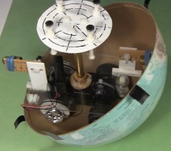
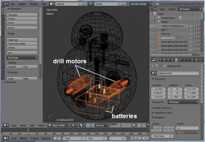
For more powerful motors and more mass I figured I could kill two birds with one stone by going with drill motors and drill batteries in a hamster drive configuration. Using drill parts kept costs down as the batteries and one drill came from yard sales while the other drill was free through freecycle.org. Meanwhile, both are heavy.
To make sure it all fit, I drew up a 3D model in Blender, the free 3D modelling and animation software that I use a lot. In fact, finding out how to make the batteries and motors fit was the first step. They had to be as low as possible. Their large mass low down is what keeps the droid vertical, with the much lighter head at the highest point.
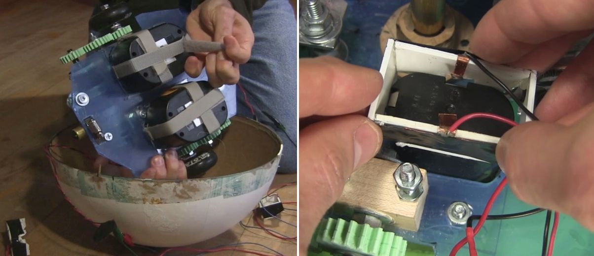
Batteries Velcroed and a connector
The drill batteries had to be easily removable for recharging. To hold them under the drive plate I simply used Velcro. Meanwhile, the drill battery stems went up through a hole in the drive plate. I made a connector to electrically connect to the battery terminals. It is a plastic rectangle with thin copper sheet metal for the contacts. Once the battery was Velcroed in place, this plastic and metal piece was lowered down onto the stem, the copper metal making contact with the battery terminals.
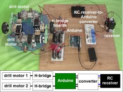
The Electronics
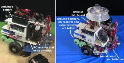
For the brains I used an Arduino UNO. To drive the motors I had all the parts for making two H-bridge driver boards, with the exception of 4 MOSFETs and some fuses. The Arduino does pulse width modulation (PWM) to the driver boards for speed control, as well as playing sounds at certain times when the motors are turned on.
For remote control, I hacked the RC receiver from the toy truck and added an extra set of AA batteries in parallel for more runtime. A problem I ran into right away though, was that the RC receiver put out voltages of both polarities based on which direction the motors should rotate, whereas the Arduino’s pins take only positive voltages. To solve that I came up with a converter board to go between them.
Getting all that to work reliably took a while. Before I added fuses, I burned a few MOSFETs. At one point I’d put an N-type MOSFET where a P-type should have gone and vice versa. That resulting problem alone took a few days of spare time to figure out.
The wheels were old Rollerblade wheels — I keep a small bucket of these in my shop. I decided I wanted the ball to roll at around 1 foot per second and doing the math, that meant the wheels would have to rotate at around 2 rotations per second or 120 RPM. I found a PWM value that would give something close to that and started blowing fuses. I started with 1 amp fuses, then 2, 5, and finally settled on 10 amp fuses.
My final hurdle was that the motors would behave oddly when the motors were told to turn in opposite directions but were fine when they were told to turn in the same direction. This turned out to be a bad assumption on my part about how the RC receiver was wired internally — none of the output wires were common inside. After some changes to the circuit, I now had stable electronics.
I had basically been treating the RC receiver as a black box, but when I asked for help about my converter board here on Hackaday, it was pointed out that the receiver likely contained H bridges. Opening it up, that’s exactly what I found. The converter board works fine for now, but in the near further I’ll use one of the suggestions from that Hackaday post to eliminate the board altogether. I might even try all of the suggestions, just for fun.
The Drive System
The drive system
The motors were too long to fit in line between the wheels and so had to be mounted off to the sides. To transfer rotation to the wheels, I drew up some gears in Blender and 3D printed them at our local University of Ottawa Makerspace. In the print settings I used 2 shells and only 50% infill. The gears are held firmly onto the shafts solely using nuts and washers on either side. They’ve held up amazingly well, even with slipping and grinding during development.
For the bearings for the center gears and the wheels I used an old trick of making bearing blocks from hardwood.
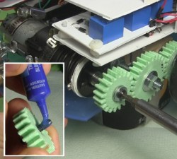
Putting Loctite and screwing gear to motor shaft
I wanted to keep as much room as possible on the drive plate available for adding things later and so initially I’d mounted the motors at only three points. But this allowed the motors to move a little causing the gears to slip. To fix that I later added a fourth mounting point and haven’t had any slipping since.
At the end of the shaft for the drill motors is a hole that a screw goes into. That’s part of how the chuck is kept on a drill motor, and that’s how one gear was kept on. However, this screw had a tendency to get loose. Putting a little Loctite on the threads fixed that.
Stability
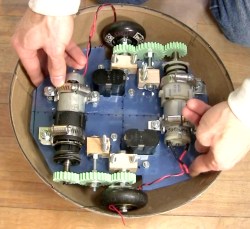
Rearranging BB-8’s internals
Given that I was trying to fit a lot in a small droid, I had to mount some things higher than I’d have liked to. When the droid stops, mass high up causes the droid to wobble. In the BB-8 droid used for promotional events they’ve gone to a great extent to keep the majority of the mass as low as possible. Originally I had the Arduino batteries and the RC receiver with its extra batteries fairly high up. I later mounted them much lower. When holding the internals in my hands I could tell the difference but it didn’t make a noticeable difference with the wobble.
Instead, for that I added Adafruit’s BNO055 inertial measurement unit (IMU) board. With it I could tell what angle the droid was at when stopping and experimented with PID loops and other algorithms of my own to minimize wobble. That helped.
The Ball
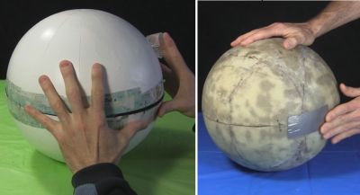
As I said, I used a 12″ cardboard globe. To increase the traction of the wheels inside the globe I sprayed the globe’s interior with an anti-slip spray from a hardware store. This made a huge difference. However, over time the anti-slip coating vanished, and so I’m looking for another, more permanent coating, perhaps urethane or something. If anyone has any suggestions, please let me know in the comments. It also has to stop off-gassing eventually. The anti-slip spray had an odor for a long time.
Sealing globes – cardboard and fiberglass
But the main problem with the cardboard globe was its thinness. With the huge weight of the internals pushing down on it where the wheels are, it warped significantly and required a lot of effort and a copious amount of tape to keep the two hemispheres together. This large amount of tape also made an uneven ridge for the head to slide over, making it get stuck. At that point either the drive system continued to move while the head fell off or the drive system couldn’t move at all.
The solution was to carefully coat a new globe in three layers of fiberglass. I took my time doing this, over a month and a half, applying one piece at a time and then sanding before putting the next piece. The result was a fantastic improvement. It no longer deformed and now it takes a minimal effort to attach the two hemispheres with only eight narrow strips of transparent duct tape.
The Never-ending Saga
My DIY BB-8 in action
My BB-8 is now at the point that I can call it finished. At least it’s finished as far as all the engineering is concerned, and that’s usually where I call it quits.
While the paint job worked out well, up close you can see that the details are painted on. It’d be nice to have at least the lines on the head be actual grooves. Also, these drill motors are brushed motors and I’ve since learned that doing high frequency PWM to brushed motors damages them over time. I’d like to replace them with brushless motors. And as anyone who’s use cordless drills a lot knows, drill batteries don’t last long, and so it’d be great to switch to LiPos.
But for now, the reactions I get from both kids and adults is beyond my wildest expectations. Kids threat it like a friend while adults have petted it and called to it like it was a baby or a dog wagging its tail. I’d call that a success.
In a time when we’re inundated with talk of an impending AI apocalypse it’s nice to see an AI that’s intentionally useless. That AI is HAL 9000. No, not the conflicted HAL from the movie 2001: A Space Odyssey but the World’s Biggest AI Useless Machine HAL built by [Rafael], [Mickey] and [Eyal] for GeekCon 2016 in Israel.
Standing tall, shiny and black, the box it’s housed in reminds us a bit of the monolith from the movie. But, in a watchful position near the top is HAL’s red eye. As we approach, HAL’s voice from the movie speaks to us asking “Just what do you think you’re doing, Dave?” as the eye changes diameter in keeping with the speech’s amplitude. And at the bottom is a bright, yellow lever marked ON, which of course we just have to turn off. When we do, a panel opens up below it and a rod extends upward to turn the lever back to the ON position.
Behind the scenes are two Arduinos. One Arduino manages servos for the panel and rod as well as playing random clips of HAL from the movie. The other Arduino uses the Arduino TVout library to output to a projector that sits behind the red diffuser that is the eye. That Arduino also takes input from a microphone and based on the amplitude, has the projector project a white circle of corresponding diameter, making the eye’s appearance change. You can see all this in action in the video after the break.
[Ken Rumer] bought a new house. It came with a troublingly complex pool system. It had solar heating. It had gas heating. Electricity was involved somehow. It had timers and gadgets. Sand could be fed into one end and clean water came out the other. There was even a spa thrown into the mix.
Needless to say, within the first few months of owning their very own chemical plant they ran into some near meltdowns. They managed to heat the pool with 250 dollars of gas in a day. They managed to drain the spa entirely into the pool, but thankfully never managed the reverse. [Ken] knew something had to change. It didn’t hurt that it seemed like a fun challenge.
The first step was to tear out as much of the old control system as could be spared. An old synchronous motor timer’s chlorine rusted guts were ripped out. The solar controler was next to be sent to its final resting place. The manual valves were all replaced with fancy new ones.
Rather than risk his fallible human state draining the pool into the downstairs toilet, he’d add a robot’s cold logical gatekeeping in order to protect house and home. It was a simple matter of involving the usual suspects. Raspberry Pi and Arduino Man collaborated on the controls. Import relay boards danced to their commands. A small suite of sensors lent their aid.
Now as the soon-to-be autumn sun sets, the pool begins to cool and the spa begins to heat automatically. The children are put to bed, tired from a fun day at the pool, and [Ken] gets to lounge in his spa; watching the distant twinkling of lights on his backyard industrial complex.
Daughter boards for microcontroller systems, whether they are shields, hats, feathers, capes, or whatever, are a convenient way to add sensors and controllers. Well, most of the time they are until challenges arise trying to stack multiple boards. Then you find the board you want to be mid-stack doesn’t have stackable headers, the top LCD board blocks the RF from a lower board, and extra headers are needed to provide clearance for the cabling to the servos, motors, and inputs. Then you find some boards try to use the pins for different purposes. Software gets into the act when support libraries want to use the same timer or other resources for different purposes. It can become a mess.
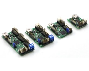
The alternative is to unstack the stack and use external boards. I took this approach in 2013 for a robotics competition. The computer on the robots was an ITX system which precluded using daughter boards, and USB ports were my interface of choice. I used a servo controller and two motor controllers from Pololu. They are still available and I’m using them on a rebuild, this time using the Raspberry Pi as the brain. USB isn’t the only option, though. A quick search found boards at Adafruit, Robotshop, and Sparkfun that use I2C.
This approach has challenges and benefits. A stack of daughter boards makes a neat package, where external boards makes a tangle of wires. Random sizes can make mounting a challenge. Providing power can also be a hassle because of the random placement of power pins. You can’t rely on USB power, especially from a Raspberry Pi whose USB is power limited.
On the other hand, external boards can offload processing from your main processor. Once a command is sent, these boards handle all the details including refresh requirements. They are likely to provide capabilities beyond the microcontroller software libraries since their processors are dedicated to the task.
I am using an 18-channel board from the Pololu Maestro Servo Controller family of boards that control from 6 to 24 servos using a single board. You might find the Adafruit 16 channel I2C board a useful alternative. For motor control I turned to the Pololu Simple Motor Controller family using one that will handle 18 amps. Others will handle from 7 to 25 amps. Or consider the Sparkfun Serial Controlled Motor Driver. Another source for USB controllers is Phidgets. I experimented with one of their spatial devices for the original robot. I should have used it to measure the tilt since one of my robots rolled over on a hill. Ooops!
Servo Control
The board currently installed on my robot is the Mini Maestro 18. The Maestro provides control over the servo speed, acceleration and movement limits. A home position can be set for startup or when errors occur. You can even do scripting or set movement sequences to play on command.
On the hardware side, the Maestro also allows channels to be used for digital input or output, and some channels for analog input. On some there is one channel for pulse width modulation output. An onboard regulator converts the servo power input to the voltage needed by the processor, simplifying part of the power distribution challenge.
My previous robot used the Maestro to control pan and tilt servos for camera positioning, a servo to lift samples from the ground, and a safety LED. Two analog inputs from current sensors on the motors helped avoid burnout during stalls, and four inputs from a simple RF key fob transmitter provided control. The latter came in handy for testing. I’d program a test sequence such as starting a 360° camera scan for landmarks or drive onto the starting platform and drop the sample. A button press on the key fob would initiate the activity. One button was always set up as an emergency halt to stop a rampaging robot. The rebuild is following this pattern with some additions.
Motor Controller
The two Simple Motor Controllers (SMC) each handled the three motors on either side of the Wild Thumper chassis. The SMC does more than just control the motor speed and direction. You can set acceleration, braking, and whether forward and reverse operate at the same or different speeds. The board monitors a number of error conditions for safety. These stop the motor and prohibit movement until cleared. Such blocking errors include lost communications, low input voltage, or drivers overheating.
An additional capability I found extremely helpful is the ability to read signals from a radio control (RC) receiver. These signals can be used to control the motor and, with some cross wiring between two controllers, provide differential drive control. This is useful for driving the robot to a new location using an RC transmitter. I didn’t use the RC inputs directly. Instead I read the RC inputs and issued the control commands from my program. This let me monitor the speed in my program logs for correlation with the other logged data. I also used an input to command the robot into autonomous or RC control operations. There are also two analog inputs that can be used to directly control the motor and can be read through commands.
Serial Communications
USB ports were my choice for communications but there is also a TTL level serial port with the standard RX and TX pins. This port can be used by the Raspberry Pi, Arduino, or any other microcontroller that has a TTL serial port.
The Maestro boards using USB appear as two serial ports. One is the command port that communications with the Maestro processor. The other is a TTL port. This port can serve as simply a USB to TTL serial port converter to allow communications with other boards, even from another vendor. Another use of the TTL port is to daisy chain Pololu boards. I could attach the SMC boards in this manner and save two USB ports for other devices. These boards support this by having a TXIN pin that ANDs the TX signal from the connected board with the TX on the board.
Both of these controllers support a few different communications protocols. I use the one Pololu created and is available on some of their other products. The command details are different between the boards, but the basic command structure is the same. They call it their binary protocol, and the basic format follows:
All the fields are single bytes except for the data field which is frequently 2 bytes to transmit 16-bit data. The returned data is only one or two bytes with no additional formatting. Note they provide for detecting errors in the message by using a CRC (cyclical redundancy check). This is probably not critical over USB but a TTL line might receive noise from motors, servos, and other devices. A CRC error sets a bit in the error register that can be read if the command is critical.
I wrote my own code, C++ of course, for the PC and converted it just now to the Raspberry Pi. The main change is the different serial port code needed by Linux and Windows. Pololu now provides Arduino source for the protocol making it easy to use these boards with that family of controller boards.
Wrap Up
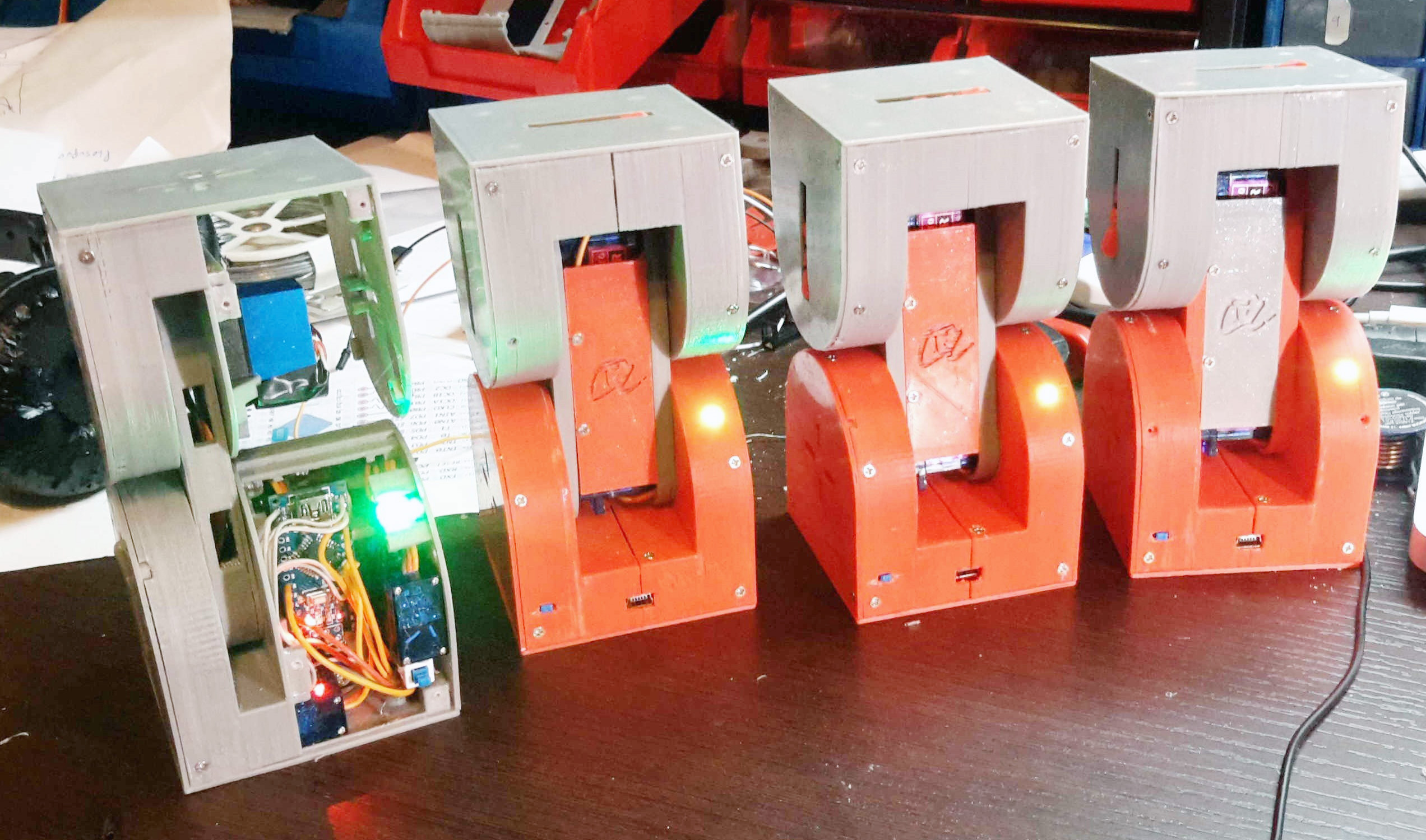
The chassis, Pi, and these boards are now installed on the Wild Thumper chassis along with a pan and tilt controlled by servos. A safety LED is on when power is applied and flashes when the robot is actively controlling the system. A LiPo battery powers all but the Pi because I need to configure a battery eliminator circuit to provide five volts. I’m powering it temporarily using a USB battery pack.
A test program, cross compiled from my desktop, moves the robot forward, pivots left than right, and then reverses. The pan / tilt moves and the LED flashes. I originally used a web camera for vision processing but will switch to the Pi camera since it is better. The Neato lidar discussed in a previous article will soon find a place onboard, along with an accelerometer to detect possible rollovers.
I’m sure I could have done this using Pi daughter boards despite the challenges I mentioned earlier. There are trade-offs to both approaches that need to be considered when working on a project. But there is one final advantage to the external boards: they have a lot of twinkly LEDs.
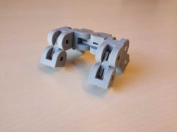
A robot to explore the unknown and automate tomorrow’s tasks and the ones after them needs to be extremely versatile. Ideally, it was capable of being any size, any shape, and any functionality, shapeless like water, flexible and smart. For his Hackaday Prize entry, [Alberto] is building such a modular, self-reconfiguring robot: Dtto.
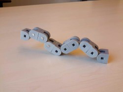
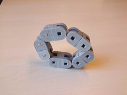
To achieve the highest possible reconfigurability, [Alberto’s] robot is designed to be the building block of a larger, mechanical organism. Inspired by the similar MTRAN III, individual robots feature two actuated hinges that give them flexibility and the ability to move on their own. A coupling mechanism on both ends of the robot allows the little crawlers to self-assemble in various configurations and carry out complex tasks together. They can chain together to form a snake, turn into a wheel and even become four (or more) legged walkers. With six coupling faces on each robot, that allow for connections in four orientations, virtually any topology is possible.
Each robot contains two strong servos for the hinges and three smaller ones for the coupling mechanism. Alignment magnets help the robots to index against each other before a latch locks them in place. The clever mechanism doubles as an ejector, so connections can be undone against the force of the alignment magnets. Most of the electronics, including an Arduino Nano, a Bluetooth and a NRF24L01+ module, are densely mounted inside one end of the robot, while the other end can be used to add additional features, such as a camera module, an accelerometer and more. The following video shows four Dtto robots in a snake configuration crawling through a tube.
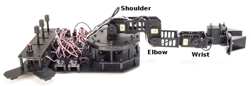
Last fall, I grabbed a robot arm from Robot Geeks when they were on sale at Thanksgiving. The arm uses servos to rotate the base and move the joints and gripper. These work well enough but I found one aspect of the arm frustrating. When you apply power, the software commands the servos to move to home position. The movement is sufficiently violent it can cause the entire arm to jump.
This jump occurs because there is no position feedback to the Arduino controller leaving it unable to know the positions of the arm’s servos and move them slowly to home. I pondered how to add this feedback using sensors, imposing the limitation that they couldn’t be large or require replacing existing parts. I decided to try adding accelerometers on each arm section.
Accelerometers, being affected by gravity when on a planet, provide an absolute reference because they always report the direction of down. With an accelerometer I can calculate the angle of an arm section with respect to the direction of gravitational acceleration.
Before discussing the accelerometers, take a look at the picture of the arm. An accelerometer would be added to each section of the arm between the controlling servos.
Accelerometers
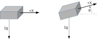
Gravity tugs everything toward the center of the mass of the Earth. It is a force that creates an acceleration exactly just like what you feel when a vehicle begins to move or stop. The force of gravity creates an acceleration of 1 g which is 9.8 m/s2 or 32.15 ft/s2. An accelerometer measures this force.
Integrated circuit accelerometers are inexpensive and small devices readily usable by hackers. One reason they are inexpensive is the high demand for them in smart phones. These small devices are based on etching mechanical structures within the integrated circuit using a technology called MEMS (Microelectromechanical systems).
One design for a MEMS accelerometer is basically a variable capacitor. One plate is fixed and the other mounted some distance away on a spring suspension. When the device is accelerated the suspended plate moves closer or further away from the fixed plate, changing the capacitance. Another uses piezo-resistive material to measure the stress on an arm caused by acceleration.
A single axis accelerometer measures acceleration in only one direction. If positioned so the direction is up and down it will measure the force of gravity but will not detect horizontal acceleration. When the device is tilted between horizontal and vertical the force of gravity is only partially affecting the measurement. This provides the ability to measure the angle of the device with the direction of gravity. The acceleration felt along the tilted axis, for a tilt angle can be calculated by:
Knowing the output of the accelerometer we can determine the angle by taking the inverse sine, the arc sine, of the output:
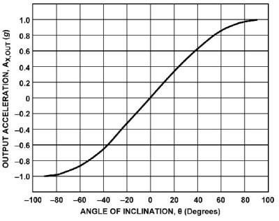
If you rotate a single axis device through 360° the output is a sine wave. Start with the device outputting zero and consider that 0°. As it rotates, the output is 1 when the angle is 90° and back to zero at 180°. Continuing the rotation, the output becomes -1 at 270°, or -90°, degrees and back to zero at 360°, or 0°.
Notice on the chart that between -60° and 60° the output is nearly linear. This is the best orientation for measuring inclination. Increases in inclination are not as accurate on the other portions of the curve. Also notice that the same output is generated for 45° and 135° (90° + 45°) creating an ambiguity. With a single axis you cannot determine which of those angles is measured.
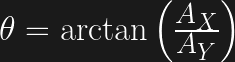
Putting two accelerometers at a right angle to one another creates a 2-axis device which solves the ambiguity problem. As the device is rotated through 360° the outputs are 90° out of phase, the same relationship as the sine and cosine. By combining the measurements there is a unique solution for every angle throughout 360°. The acceleration due to gravity at each angle is given by:
which leads to calculating the angle by:
Actually, one more step is needed to determine the sign of the angle. This requires examining the sign of the values for the X and Y axis. It isn’t necessary to go into this here because a standard programming function handles this automatically.
The orientation of a quadcopter requires a 3-axis accelerometer. The calculations for the three spherical angles combine all three inputs for their results. You’ll need to study this carefully because the standard trigonometric equations can cause anomalies when the quadcopter flips.
First Pass Solution
Accelerometers are easily obtained and relatively cheap. You can find them mounted on breakout boards with voltage regulators and all the supporting circuits from the usual vendors. They are available for 1 to 3 axis, various amounts of g force, and providing either analog or digital outputs. Analog devices need an analog input for each axis being measured. Digital outputs use I2C or SPI buses for communications. I decided to use analog devices because digital units typically only allow two addresses and the arm needs three devices, one for each section.
The robot arm uses an Arduino board so there are at least 6 analog inputs. The original board was a Robot Geek Geekduino, their version of the Arduino Duemilanove, with 8 analog inputs. Unfortunately, when working with the arm I broke the USB connector so switched to a Uno equivalent having only 6 inputs.
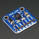
My choice for accelerometer is a 3-axis, ±3 g accelerometer breakout from Adafruit, their ADXL335. It has one analog output for each axis. Since I’m measuring three joints that means three boards which adds up to 9 analog outputs.
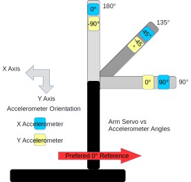
Because of the geometry of the arm, however, I only need 5 inputs for these three joints. The shoulder joint only moves from 0° to 180°. This can be handled by a single axis accelerometer by mounting it to read acceleration of 1 g for 0° and -1g for 180°. That provides a unique output for the necessary angles. The elbow and wrist joints each require two inputs. The third input is not needed because their motion is constrained to moving within the vertical plane of the arm.
Frame of Reference
The next issue is the frame of reference. This is a standard problem in robotics work. Early in a project, a global frame of reference is decided upon. This sets the origin for the coordinate system that the robot will follow and the direction of the three axes, usually specified as X, Y, and Z. For the arm, X is straight forward, Y is to the left, and Z is straight up. The zero point is the base of the shoulder. This also defines a global frame for rotation of the arms limbs with zero degrees also toward the front.
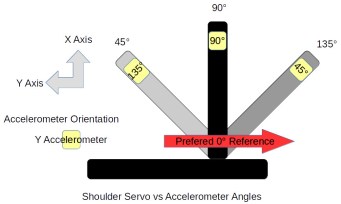
Sensors and controllers each have their own frame of reference. Any differences among these devices and the global frame need to be resolved in software. The shoulder servo’s frame of reference is 0° at the back of the arm and 180° at the front, a clockwise rotation. This is the reverse of the global frame. The elbow servo worked the opposite with a counter-clockwise rotation putting 180° straight up and 90° straight out when the shoulder was vertical. It is 90° off from the global frame of reference.
Sensors also have their own frame of reference. The Y-axis accelerometer measuring the shoulder orientation worked counter-clockwise. Both axis on the accelerometers measuring the elbow worked in the clock-wise direction. This may seem strange but it’s because of the different mounting orientations of the sensors.
Software
The actual code is straightforward once the frame of references are sorted out. A single axis is read from the analog input and its angle calculated with:
The read() method scales the raw analog input values so ±1g is represented as ±100. The input to asin() is divided by 100.0 to convert to the actual g value. That suffices for the shoulder angle.
The elbow and wrist angles use values from two axis and the calculation is:
const int elbowx = elbowAnalogX.read();
const int elbowy = elbowAnalogY.read();
float elbow_angle = degrees(atan2(-elbowy, elbowx));
The atan2() function is a special version of the arc tangent calculation. It examines the signs of the input value to determine the quadrant of the angle to set the appropriate sign on its result. The negative sign on the elbowy is needed to set the appropriate quadrant. There’s the frame of reference issue, again.
Wrap Up
Adding the accelerometers solved the startup lurching problem well enough. Whether the accelerometers can be used for other purposes remains to be seen.
The accuracy of the angle measurements is not good. In part this is due to using a device that with a +/- 3 g range to measure 1/3 of the devices range, 1 g. The device outputs 0 to 3.3 volts while the Arduino is sampling for 5 volts, again losing accuracy. This might be improved by using an Arduino based on 3.3 volts. I have a couple Dues on hand so might try them. The Uno also provides for adjusting the reference voltage for analog inputs so setting it to 3.3 volts might help.
The analog values need to be calibrated with some care. Each accelerometer outputs slightly different values. Calibration requires measuring the outputs for 1 and -1 g for each axis, recording the values, and using them to scale the voltage input to acceleration. This calibration is not accurate given the other problems with the analog inputs.
Another problem is the mounting of the accelerometers on the arm’s sections. The alignment of the boards with the sections of the arm is not perfect. When the servo is positioned at 90° the accelerometer doesn’t necessarily sit at 90° with respect to the center of the earth. Of course, the servos are not that precise, either. They do not always arrive at the same position, especially when approaching from different directions. Another goal for this project was to use the accelerometer information to more precisely position the servos.
I guess I have to think about this project a bit more, including deciding what I actually want to accomplish with the arm. But then, just saying you have a robotic arm is a terrific hacking cred.


 On the hardware side, the Maestro also allows channels to be used for digital input or output, and some channels for analog input. On some there is one channel for pulse width modulation output. An onboard regulator converts the servo power input to the voltage needed by the processor, simplifying part of the power distribution challenge.
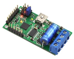 An additional capability I found extremely helpful is the ability to read signals from a radio control (RC) receiver. These signals can be used to control the motor and, with some cross wiring between two controllers, provide differential drive control. This is useful for driving the robot to a new location using an RC transmitter. I didn’t use the RC inputs directly. Instead I read the RC inputs and issued the control commands from my program. This let me monitor the speed in my program logs for correlation with the other logged data. I also used an input to command the robot into autonomous or RC control operations. There are also two analog inputs that can be used to directly control the motor and can be read through commands.
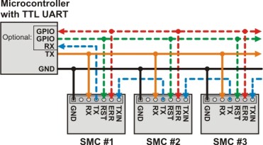 The Maestro boards using USB appear as two serial ports. One is the command port that communications with the Maestro processor. The other is a TTL port. This port can serve as simply a USB to TTL serial port converter to allow communications with other boards, even from another vendor. Another use of the TTL port is to daisy chain Pololu boards. I could attach the SMC boards in this manner and save two USB ports for other devices. These boards support this by having a TXIN pin that ANDs the TX signal from the connected board with the TX on the board.


 A single axis accelerometer measures acceleration in only one direction. If positioned so the direction is up and down it will measure the force of gravity but will not detect horizontal acceleration. When the device is tilted between horizontal and vertical the force of gravity is only partially affecting the measurement. This provides the ability to measure the angle of the device with the direction of gravity. The acceleration felt along the tilted axis, for a tilt angle can be calculated by:


 My choice for accelerometer is a 3-axis, ±3 g accelerometer breakout from Adafruit, their ADXL335. It has one analog output for each axis. Since I’m measuring three joints that means three boards which adds up to 9 analog outputs.