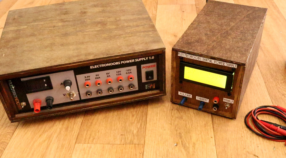
If you want a DC power supply that works well, there are a number of places to buy such a device. If, however, you want to learn how one operates, and perhaps build your own, the video below by YouTuber Electronoobs will show you how to accomplish this feat.
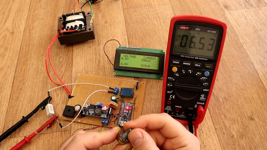
His project uses a transformer to step power down from the 230VAC available in Spain, along with a rectifier to produce DC current, and a capacitor to keep the output steady. An Arduino Nano produces a PWM signal that controls a MOSFET on the buck converter circuit, tuning the output voltage and current as needed based on user inputs.
Details can be found on Electronoobs’ website here, though you’ll want to use extreme caution when dealing with mains power. Also, the design will need to be modified if your country uses something other than 230VAC.
Woodworking with power tools creates dust. Lots of it. Hooking a vacuum up to your tool helps greatly, but only if it’s actually running. Annoyed with turning on his vacuum system every time he had to make a cut, Zach Hipps decided to automate the process.
What he came up with uses an ACS712 current sensor to detect when power is flowing to his table saw, and an Arduino Nano for control. When current is sensed, it triggers the vacuum using a relay, then holds it on until five seconds after the device is turned off.
If I’m going to be able to automatically turn on the shop vac, I need to be able to detect when the tool is turned on and running. Without modifying the tool, the best way to do this is to get a current sensor like the ACS712 which I also got on eBay for a couple of bucks. This sensor can read alternating or direct current up to 20 Amps which is perfect for what I’m going to be using it for. The sensor outputs an analog voltage between 0 and 5 Volts that is proportional to the current it senses. I can read that analog voltage output with one of the ADC pins on the Arduino. Once I sense that the tool is running, I need to be able to turn on the shop vac. For that I’m going to use the relay module. A simple high or low logic signal from one of the Arduino’s digital pins is all that is needed to turn on the relay.
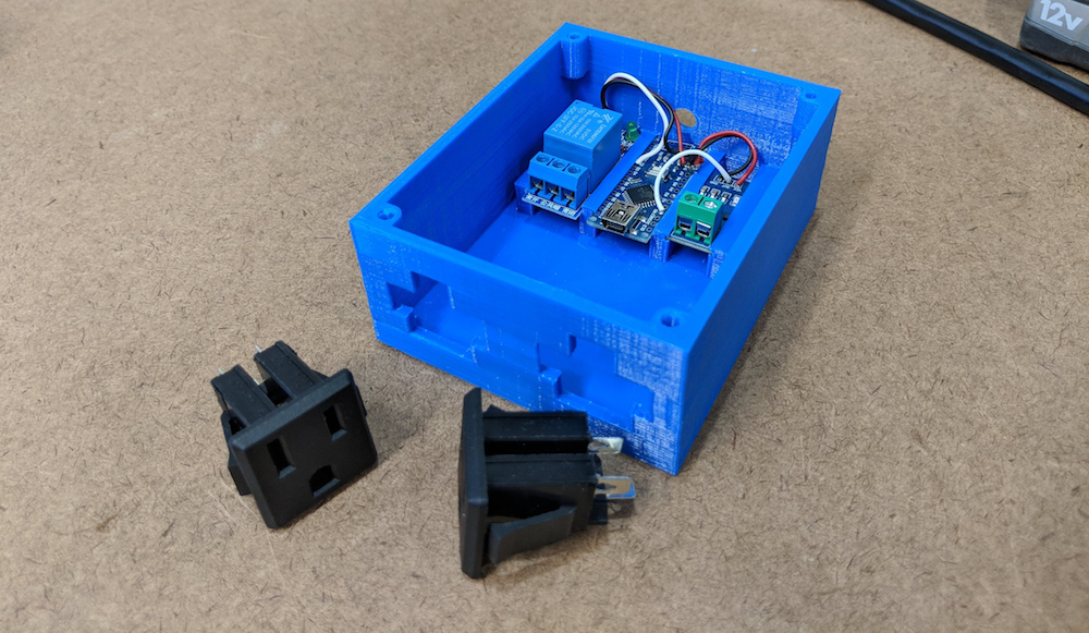
After I had the two modules soldered to the Arduino, I decided to model and 3D print an enclosure that will secure everything in place. With the enclosure done, I can wire in the AC power receptacles. One receptacle for the tool and one for the shop vac. Having these will make it easy to move this around my garage and plug in various tools. I bought an extension cord to use for this project and cut off about 8 inches of the male end.
If you’ve ever seen a MIDI pad with dozens of light-up buttons producing electronic music, you may have considered building one using an Arduino. As shown in GreatScott!’s latest write-up, you can indeed create your own Novation Launchpad-like device using a Nano for control, but the real question is should you?
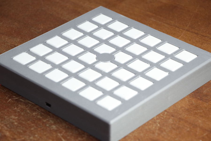
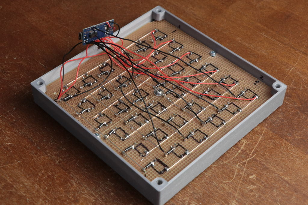
In the video below, GreatScott! shares how made a 6×6 pad, using a 3D-printed body and buttons arranged in a matrix to save I/O, along with WS2812B LEDs. He also goes over the MIDI protocol, which he was able to implement using loopMIDI and Hairless MIDI to serial bridge for Arduino interface.
While the DIY option may or may not be right for you, the concepts presented could be applied to a wide range of electronic musical interface projects.
In this episode of DIY or Buy I will be showing you how I created my own Launchpad. That means I will show you how I combined a design idea with 3D prints, WS2812 LEDs, tactile switches and an Arduino to create a proper MIDI instrument. While building I will also tell you a bit about a keyboard matrix and in the end determine what advantages the DIY Launchpad offers.
Tulips come in all shapes and sizes, but Jirí Praus has created a mechanical version like nothing you’ve ever seen. It’s masterfully crafted as a gift for his wife, using bent wire to form its six petals and stem.
In order to make this present truly amazing, however, a servo-driven linkage system opens up the tulip when touched, exposing seven programmable LEDs in the center, along with 30 bright white SMD LEDs on the petals themselves.
Control for the freeform flower is accomplished via an Arduino Nano, hidden inside its wooden base. It’s a truly spectacular build, shown below illuminating the surrounding area with a brilliant light and shadow pattern.
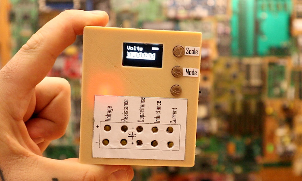
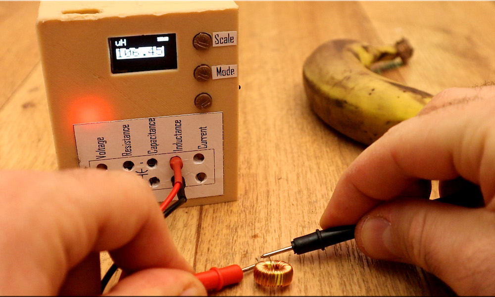
If you ever wondered about building your own multimeter, YouTuber Electronoobs shows us just how to do so with an Arduino Nano.
Aside from the Nano, he’s using a 128×64 OLED screen to display stats and battery level, and a 16-bit ADC for precise measurements. Power is provided by a small onboard LiPo battery, and he’s even included a charging module to help keep things topped off. Everything is housed inside a custom 3D-printed case.
The device doesn’t just measure voltage, resistance, and current, but is capable of reading capacitance and inductance as well—measurements that you wouldn’t necessarily expect on a commercial meter. If you’d like to create your own, the schematic and code are available on Electronoobs’ site.
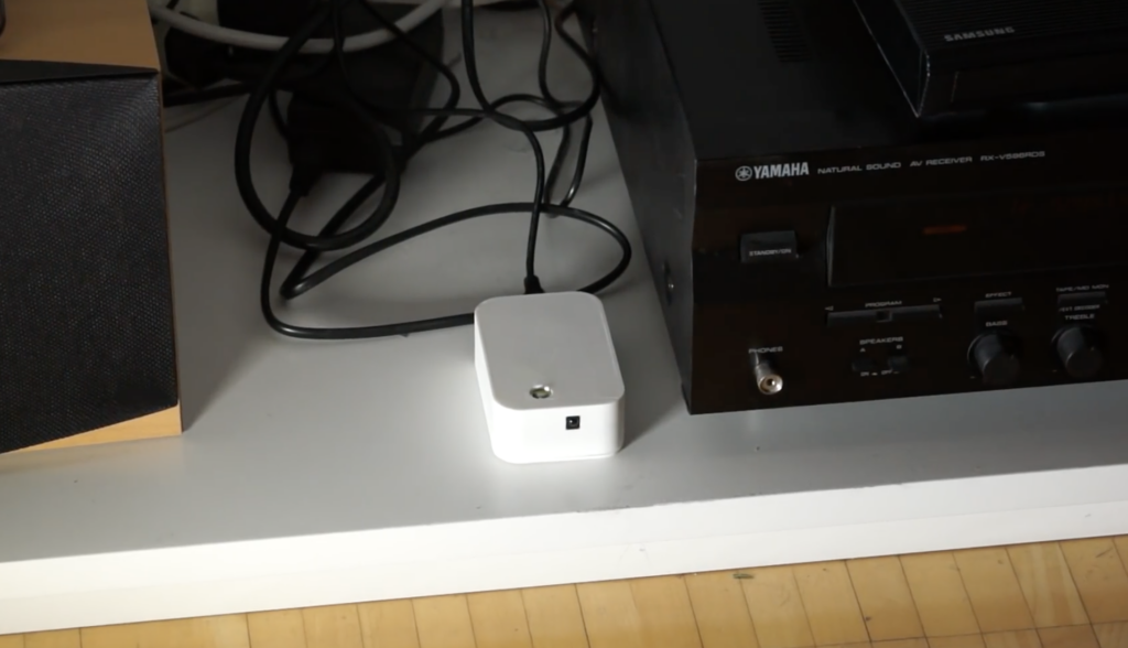
After purchasing a new television, maker Andreas Spiess’ remote no longer worked seamlessly with the controller his family had been using. While a universal remote could have solved the problem, in order to keep things simple to use, he instead came up with an infrared “babel fish” signal translator—named after the language translation animal Hitchhiker’s Guide to the Galaxy’s.
The device receives infrared signals from the original remote, then uses an Arduino Nano to pass the properly translated pulses on to his TV and receiver. A 3W IR diode transmits these new signals with the help of an N-channel MOSFET, giving it enough power to control each component, even without the proper line-of-sight orientation.
It’s a hack that could be useful in many situations, and Speiss goes over how it was made, along with design requirements in the video below.
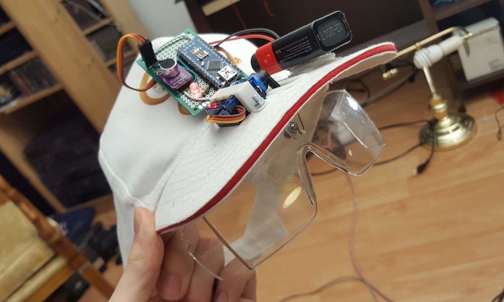
Görkem Bozkurt has a bit of a problem. When he gets going with a build, sometimes safety glasses are forgotten in the excitement of making something new. While understandable, this doesn’t make things any less dangerous, so he came up with a novel idea to put on his safety specs on automatically.
His wearable creation attaches an Arduino Nano and a MAX4466 electret mic amplifier to the top of a previously normal hat, along with a small servo connected to a pair of lens below the bill. If a loud sound is heard, the goggles are lowered by the servo in response. They’re then retracted when the noise, and hopefully the danger, is gone.
While the system is still very much a work-in-progress, it’s an entertaining concept that Bozkurt hopes to develop further.
When you build one-off projects for yourself, if it doesn’t work right the first time, it’s a nuisance. You go back to the bench, rework it, and move on with life. The equation changes considerably when you’re building things to sell to someone. Once you take money for your thing, you have to support it, and anything that goes out the door busted is money out of your pocket.
[Brian Lough] ran into this fact of life recently when the widget he sells on Tindie became popular enough that he landed an order for 100 units. Not willing to cut corners on testing but also not interested in spending days on the task, he built this automated test jig to handle the job for him. The widget in question is the “Power BLough-R”, a USB pass-through device that strips the 5-volt from the line while letting the data come through; it’s useful for preventing 3D-printers from being backfed when connected to Octoprint. The tester is very much a tactical build, with a Nano in a breakout board wired to a couple of USB connectors. When the widget is connected to the tester, a complete series of checks make sure that there are no wiring errors, and the results are logged to the serial console. [Brian] now has complete confidence that each unit works before going out the door, and what’s more, the tester shaved almost a minute off each manual test. Check in out in action in the video below.
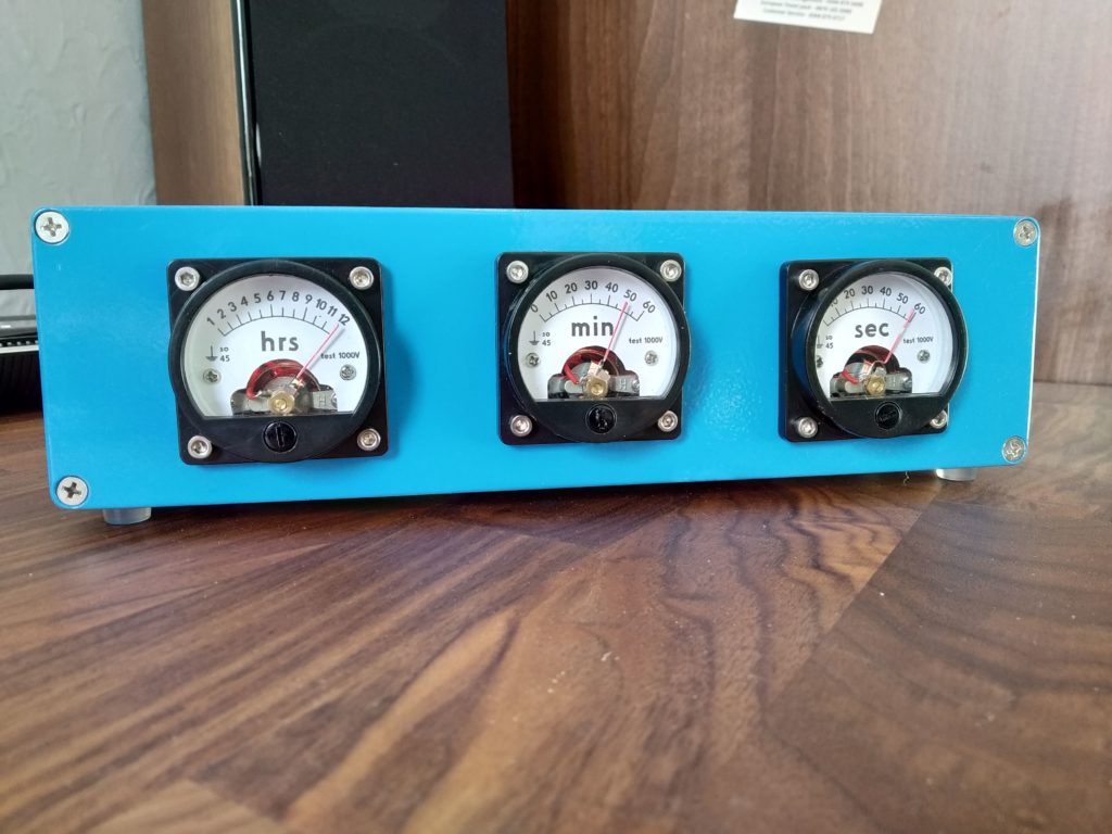
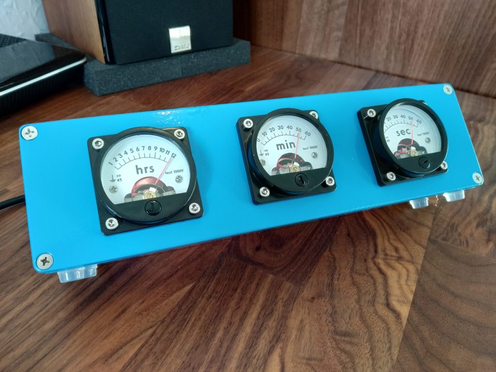
Apparently not satisfied with available timekeeping devices, ElegantAlchemist crafted a unique clock using an Arduino Nano, an RTC module, and three formerly 1000VAC analog meters.
The first order of business for the build was converting the meters into something that could traverse its range with only 5V, accomplished by replacing the stock resistor, diode, and capacitor with a 2.2kohm resistor.
Now controllable via Arduino, new faceplate labels were designed in CorelDraw for a very professional look. Everything was encased in an aluminum stomp box enclosure—actually several as multiple clocks were constructed—and RGB LEDs were also added behind each display.
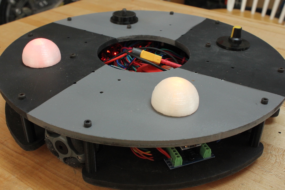
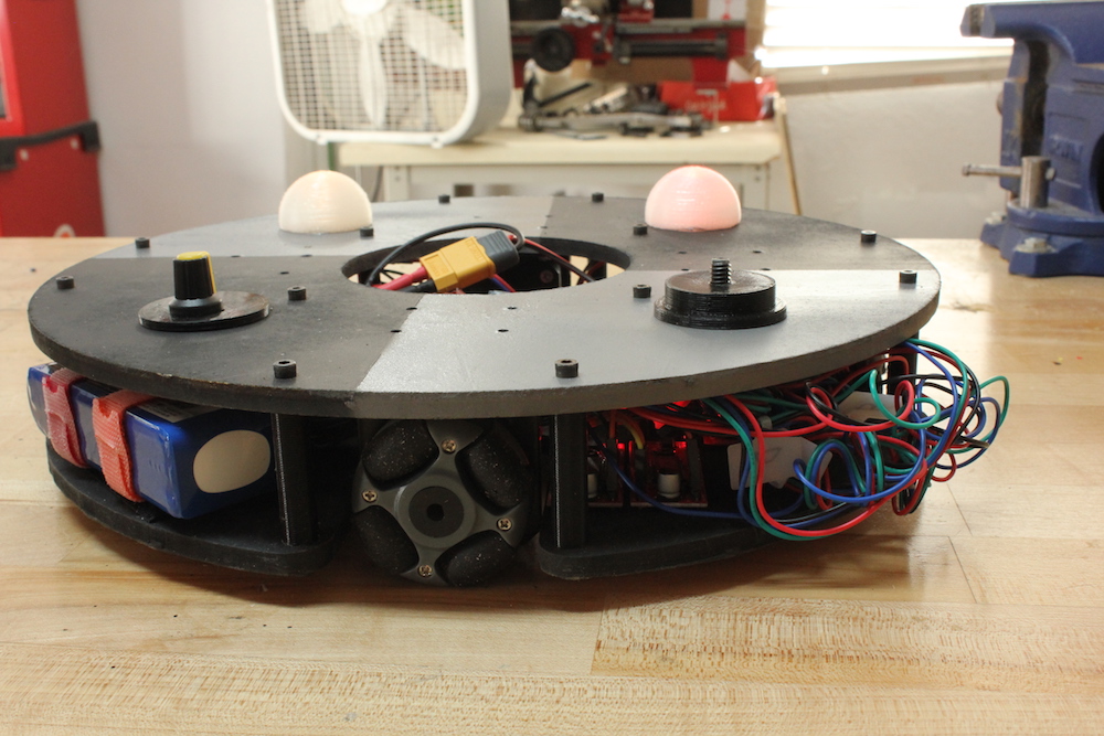
When we last saw this omni robot by Jeremy S. Cook, it was lurching around under Arduino Nano and Bluetooth command. After much work, he finally has it to a state where it rolls nicely on a flat surface—even carrying a little strandbeest at just after 8:30 in the demo video.
The biggest revision for the robot was new “grippier” wheels, but electronics were also enhanced, including a LiPo battery (with a voltage divider monitoring circuit), potentiometer for speed control, and LED eyes.
Changes were facilitated by a screw terminal board attached to the Nano, which minimized solder work, while keeping the robot’s wiring secure. More details and code are available here, while the upgrade/troubleshooting process can be seen in the video below.