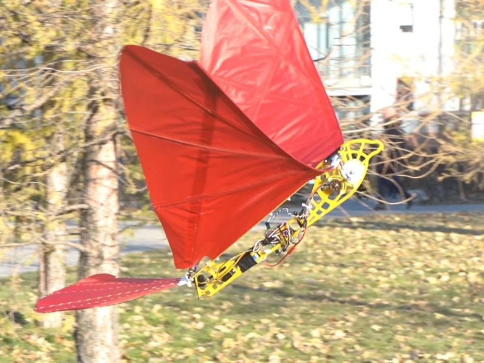
While much less common than quadcopters or airplanes, if you want a device that truly soars like a bird, you need an ornithopter. To help others make their own flying contraption, YouTuber Amperka Cyber Couch is outlining the build process in a video series starting with the one seen below.
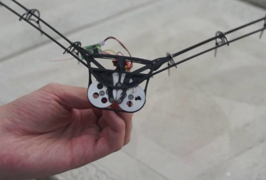
Construction is also very well documented in his project write-up, and a clip of it in-flight can be found here. The bionic ‘bird’ uses a BLDC/ESC combination to turn a gearbox that flaps its wings, and an onboard Arduino Nano for control.
Communication is via an MBee 868 wireless module, which links up to an Arduino Uno base station that provides its user interface.
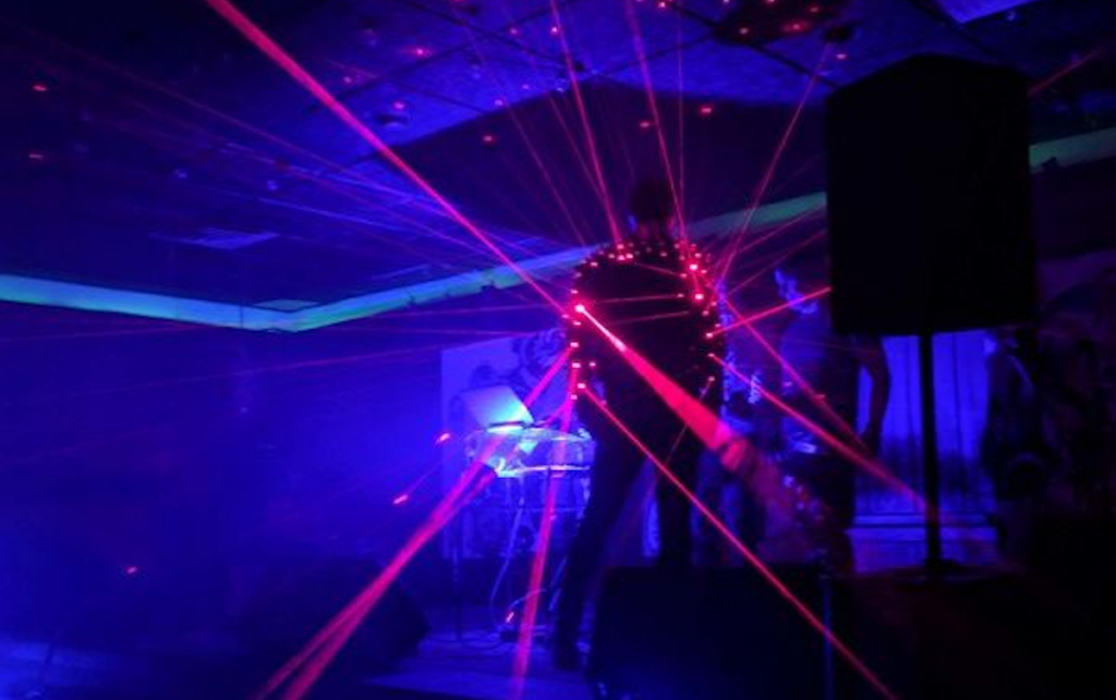
Your leather jacket might look cool, but one thing it’s missing—unless you’re maker “abetusk” or perhaps a Japanese musician—is lasers!
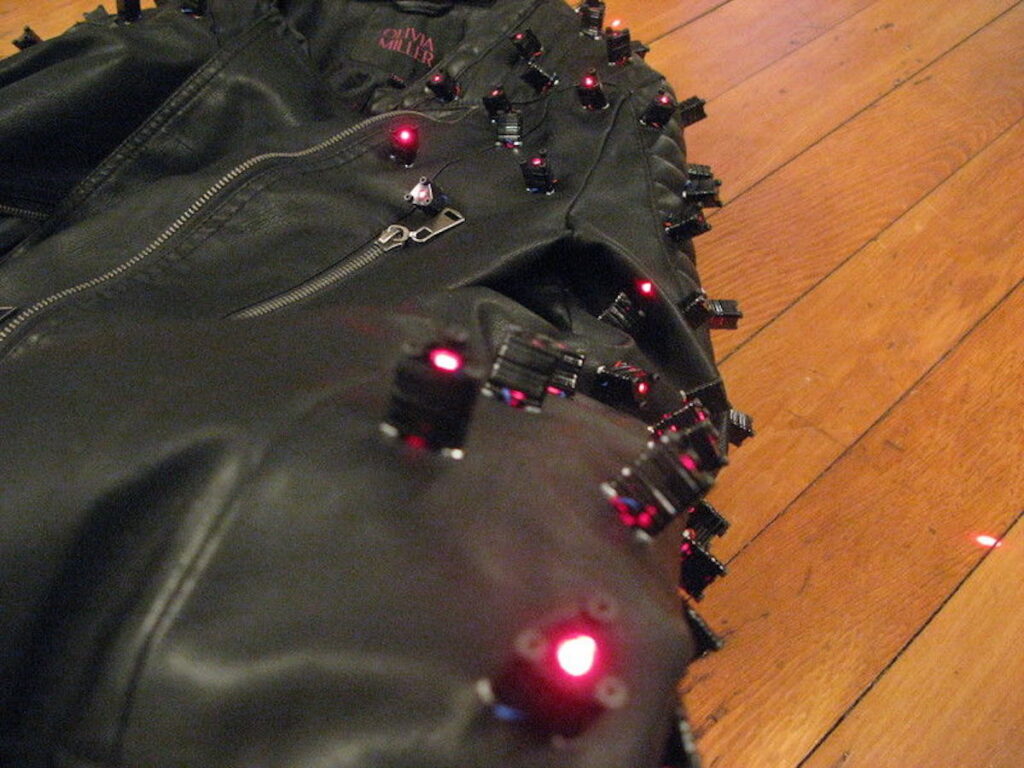
After seeing Yoshii Kazuya’s laser-spiked outfit, ‘tusk decided to create an excellent version of the getup by embedding 128 laser diodes embedded in his own jacket. These lasers are powered by an Arduino Nano, along with a pair of I2C PWM output boards, allowing them to be switched in sets of four.
The lasers can be controlled either by joystick, via a microphone in order to react to sound, or in a looping ‘twinkle’ pattern.
More information on the project is available in this write-up as well as on GitHub, which includes Arduino code and other files needed to build your own.
After seeing Wei Chieh Shi’s laser jacket design, I wanted to create my own. These instructions show how to modify a jacket to add laser diodes and control them electronically to produce different laser light patterns. The laser diodes give the jacket an appearance of being “spiky”, like having metal spikes but with red laser light. The effect is especially striking in environments with fog or smoke as the laser light path shows a trail from where it originates.
The concept and execution is relatively simple but care has to be taken to make sure that the electronics, wiring and other aspects of the jacket don’t fail when in use. Much of the subtlety and complexity of the project is providing proper wire routing and making sure that strain relief for the electronics and connections is provided so that it’s resilient under normal wear.
Assuming the basic parts are available (soldering iron, multimeter, wire strippers, laser cutter, etc.) I would estimate that this project is about $300 in raw materials and about 20 hours worth of labor.
Depending on the battery used, the jacket can operate for about an hour or two continuously. Spare batteries can be carried around and used to replace the depleted batteries if need be.
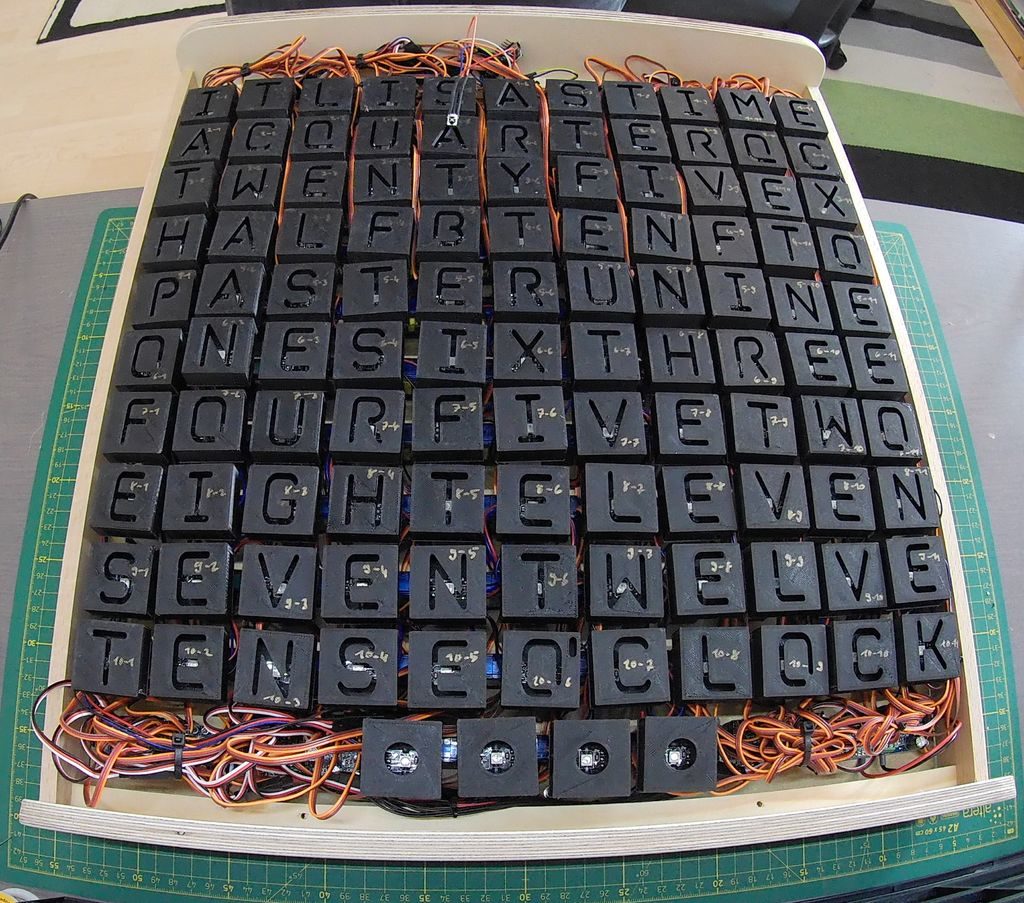
Word clocks normally use an array of lights to show the time, and although this project does use lights, how it works is much different than others.
LEDs for the device are hidden behind a thin layer of PVC, while 114 tiny SG90 servos move the lights and their 3D-printed frames back and forth. The result is a stunning display where the time is spelled out by the appropriate letters. These progressively come into focus, setting them apart from inactive letters which appear to fade into the background.
An Arduino Nano drives the assembly, along with an infrared controller setup and an RTC module for accurate timekeeping. A demo can be seen in the first video below, and the very involved build process is highlighted in the second clip.
What has 114 LEDs and is always running? As you may know the answer is a word clock. What has 114 LEDs + 114 servos and is always moving? The answer is this servo controlled word clock.
For this project I teamed up with a friend of mine which turned out to be a must because of the large effort of this build. In addition, my electronic and his mechanical skillset complemented each other quite well. The idea for this adaptation of the popular word clock came to us while we were making a regular one as Christmas gift. There, we noticed that it is also possible to project the letters from the back onto a white sheet of paper. At the time this was only a workaround solution to hide our crappy craftsmanship since we ended up with a lot of bubbles while attaching a vinyl sticker with the letters to the back of a glass plate. We then noticed that one can achieve interesting effects when bending the sheet of paper since the letters change size and become blurred. This made us come up with the idea to make a word clock where the letters are projected from the back onto a screen and can be moved back and forth to change the size of the projected image. At first we were a bit reluctant to build this project because of the costs and effort it takes when you want to move each of the 114 letters individually. So we tossed with the idea to make a version where just every word that is used to display the time can be moved back and forth. However, after seeing that the Epilog contest was coming up on Instructables asking for epic projects, and also after finding relatively cheap servo motors, we decided to go all the way and make a proper version where each letter is individually controlled by a servo
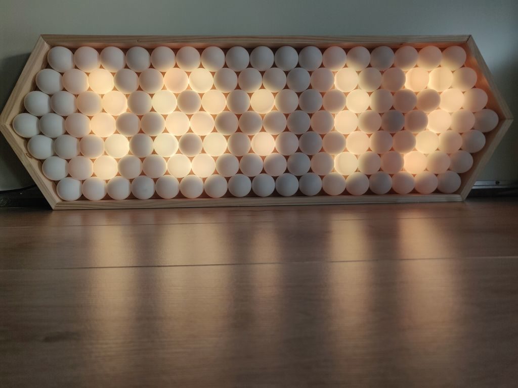
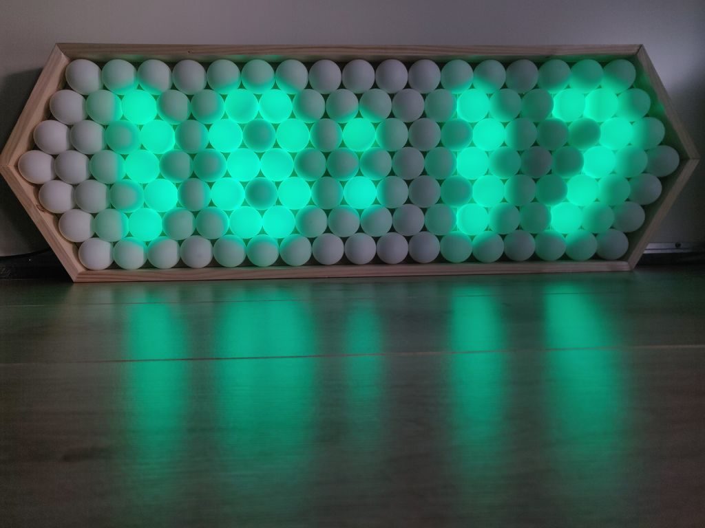
Ping pong balls have long been known as excellent LED diffusers, but few have taken this technique as far as Thomas Jensma. His colorful clock features 128 LEDs, arranged in an alternating pattern, and housed in a stretched-out hexagonal wood frame.
For control, the device uses an Arduino Nano, along with a RTC module for accurate timekeeping. Demos of the clock can be seen below, cycling through numbers and testing out the FastLED library.
Code for the build is available in Jensma’s write-up. This also includes tips on using table tennis balls as diffusers, as well as how to create an orderly array out of these spheres—useful in a wide range of projects.
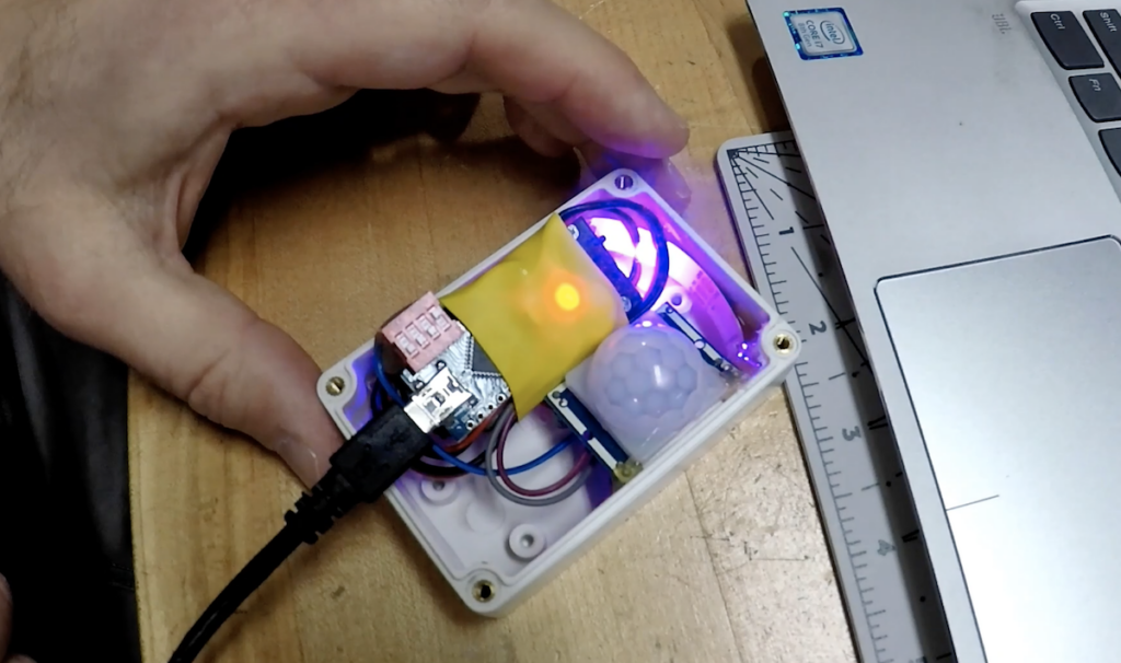
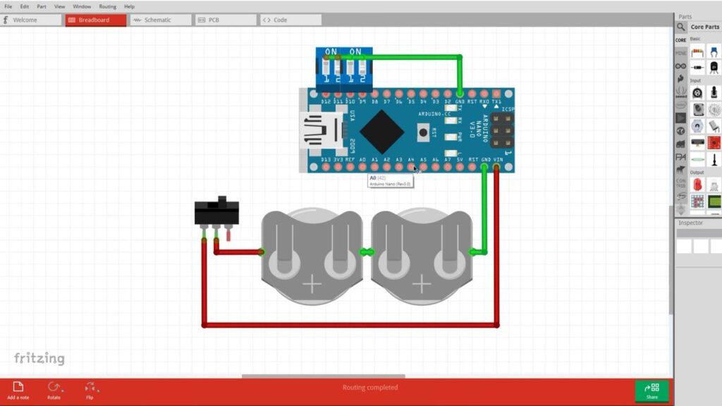
Arduino boards are used in a wide—massive even—variety of projects. Sometimes, however, all you need is something to give your project the ability to blink an LED, sound an alarm, or accomplish some other simple task.
For this purpose, maker Jeremy S. Cook has developed a sort of standard method for using these devices, with a 4-position DIP switch soldered to inputs D9-D12, and a double-CR2032 battery pack attached with shrink wrap.
This standardization makes for a very compact setup that can be implemented in a project very quickly. The configuration also highlights the use of “INPUT_PULLUP” in Arduino code, with switches wired to ground. Cook’s technique avoids floating inputs without the need for external resistors.
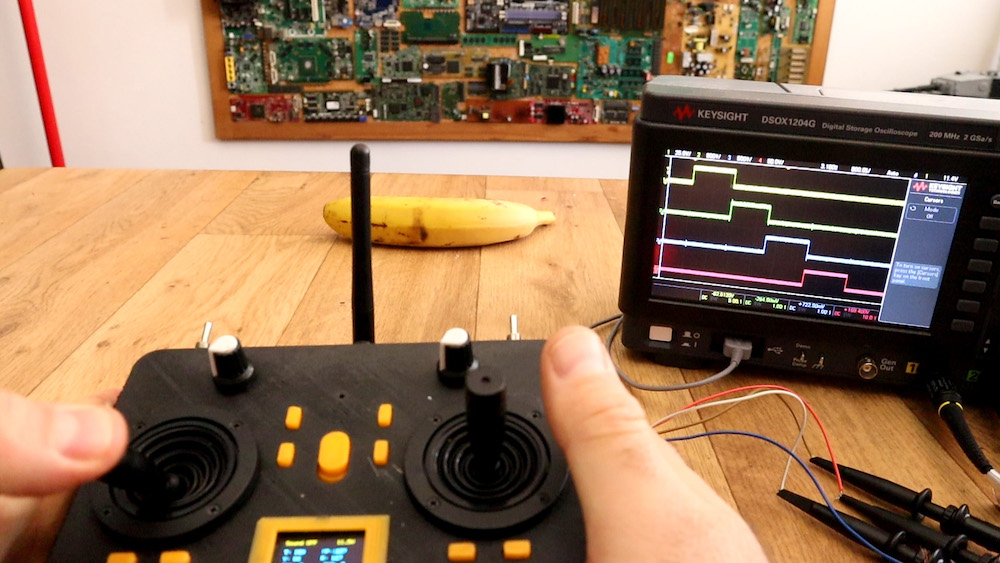
If you’ve ever considered constructing your own wireless RC transmitter, be sure to check out this build by Electronoobs.
The device uses an nRF24L01+ module to transmit inputs from a pair of joysticks and toggle switches, along with an Arduino Nano for interface and control.
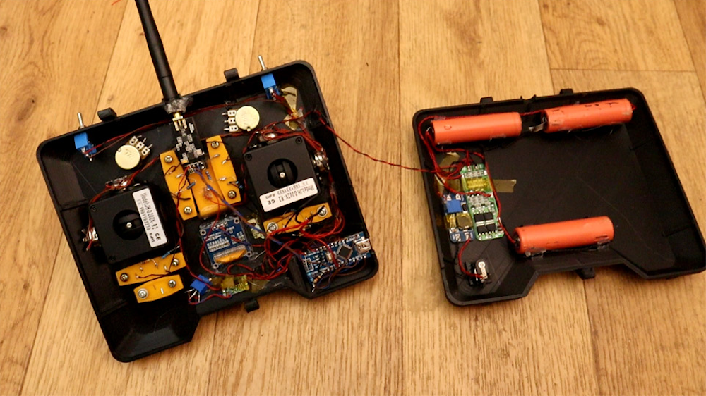
What sets this project apart from his previous versions, however, is the very nice 3D-printed enclosure for the electronics and a pair of high-quality joysticks that allow for precise input.
Additionally, Electronoobs’ latest design features tuning buttons to properly center the sticks, and an OLED display to show the actual input value that it’s sending to the receiver (a simple Nano/nRF24L01+ setup for demo purposes).
Yes, I’ve made another radio controller. Why? well, I wanted to have a more commercial look. So, I’ve designed a 3D case, then I’ve used some high quality joysticks in order to have better analog read, It has an OLED screen so we could see the data we send and we could also digitally adjust the data. It also has 2 modes, linear and exponential
When your car door isn’t shut quite correctly, you’ll normally look down at the dash to see what the problem is. What if, instead of a small 2D picture of your doors, you had a tiny actuated version of your vehicle on your dash?
Mathis Ochsenmeier’s Analogous Door Display is exactly that. It mirrors his VW van’s front and rear doors using an Arduino Nano to take in sensor information and actuate three servo motors to mimic door positions.
Now when the van’s front doors or rear hatch open or close, the little van on the dash’s doors follow suit—both a useful diagnostic tool, and an entertaining model.
Maker Jeremy S. Cook has experimented with both CNC machinery and light painting in the past, and decided to combine these two skills into a new artistic device.
His setup uses a web app found here to program a CNC router as a sort of dot matrix printer. But instead of a pen, pencil, brush or other marking utensil, it uses a button as an input to the onboard Arduino Nano when pressed to the router’s surface.
From this input, the Arduino then commands a diffused RGB LED to “mark” the surface with light, painting an image on the camera’s exposed sensor.
Code and print files are are available on GitHub if you’d like to try your own light art experiments!
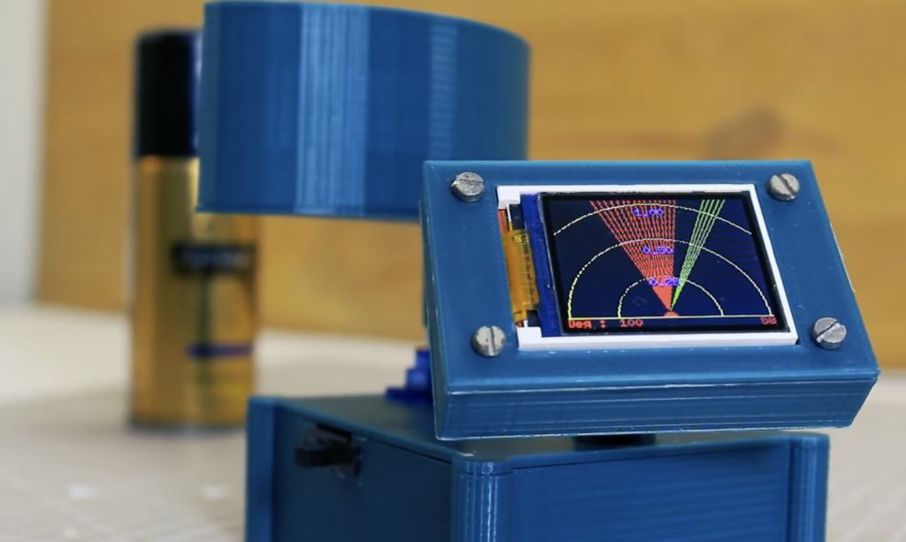
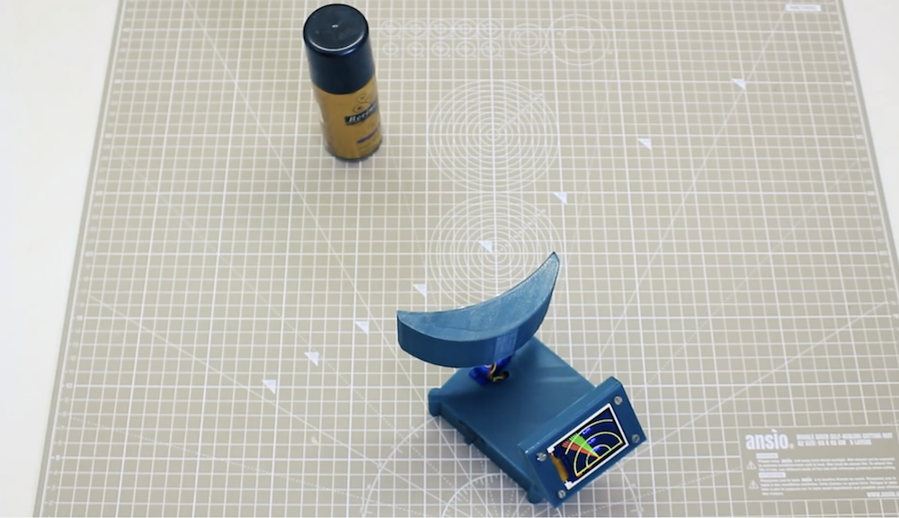
Ultrasonic sensors, which emit a high frequency sound wave then listen for its return to determine an object’s distance, are useful in a wide variety of robotics projects. If you’d like a visualization of how the sensor views an area, this “radar” from Mr Innovative presents a fun option.
The 3D-printed console features a small SG90 servo to pan the sensor over a space, picking up obstacles in its path. The readings are then transmitted to an Arduino Nano, which displays object info on a TFT screen set up to look reminiscent of a radar screen.
I have made a mini compact radar with display for that I have used HC-SR04 ultrasonic sensor, this sensor emit ultrasonic sound which came back to sensor after reflecting from an object, all the data visualization is displayed on 1.8″ ST7735 display, if any object detect by radar it’ll show in display in red line.
The build could function either as a great teaching tool, or perhaps the basis for a panning robot sensor. Print files can be found here, and code is available on GitHub.
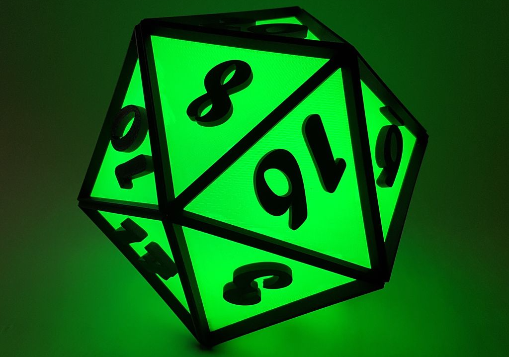
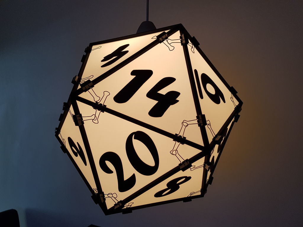
Regular icosahedrons are 20-sided polyhedrons formed out of equilateral triangles. As such, the geometry behind making one is slightly complicated, but the results in the case of this large light-up device appear to have been well worth it.
The project’s write-up does go over how to actually model these faces in CAD but also provides the 3D print files if you’d like to skip to building your own. Two versions were made, including a device that illuminates RGBW LEDs under Arduino Nano control, and a second icosahedron large enough to be used as a lamp shade!
A demo/explanation is seen in the first clip below, along with a better look at the electronics in the breadboard video.