Posts with «lcd» label

Tutorial – Using the 0.96″ 80 x 160 Full Color IPS LCD Module with Arduino

The purpose of this guide is to get your 0.96″ color LCD display successfully operating with your Arduino, so you can move forward and experiment and explore further types of operation with the display. This includes installing the Arduino library, making a succesful board connection and running a demonstration sketch.

Although you can use the display with an Arduino Uno or other boad with an ATmega328-series microcontroller – this isn’t recommended for especially large projects. The library eats up a fair amount of flash memory – around 60% in most cases.

So if you’re running larger projects we recommend using an Arduino Mega or Due-compatible board due to the increased amount of flash memory in their host microcontrollers.

Installing the Arduino library

So let’s get started. We’ll first install the Arduino library then move on to hardware connection and then operating the display.

(As the display uses the ST7735S controller IC, you may be tempted to use the default TFT library included with the Arduino IDE – however it isn’t that reliable. Instead, please follow the instructions below). 

First – download the special Arduino library for your display and save it into your Downloads or a temp folder.

Next – open the Arduino IDE and select the Sketch > Include Library > Add .ZIP library option as shown below:
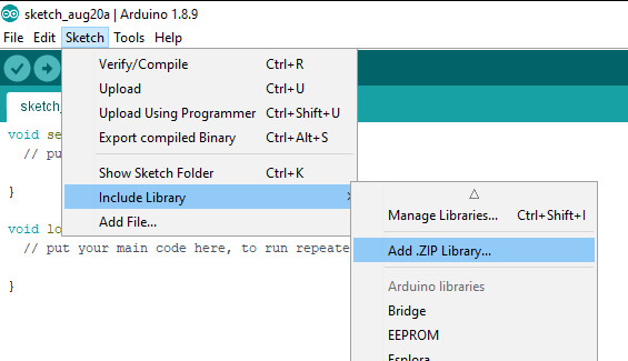
A dialog box will open – navigate to and select the zip file you downloaded earlier. After a moment or two the IDE will then install the library.

Please check that the library has been installed – to do this, select the Sketch > Include Library option in the IDE and scroll down the long menu until you see “ER-TFTM0.96-1” as shown below:

Once that has been successful, you can wire up your display.

Connecting the display to your Arduino

The display uses the SPI data bus for communication, and is a 3.3V board. You can use it with an Arduino or other 5V board as the logic is tolerant of higher voltages.

Arduino to Display

GND ----- GND (GND)
3.3V ---- Vcc (3.3V power supply)
D13 ----- SCL (SPI bus clock)
D11 ----- SDA (SPI bus data out from Arduino)
D10 ----- CS (SPI bus "Chip Select")
D9 ------ DC (Data instruction select pin)
D8 ------ RES (reset input)

If your Arduino has different pinouts than the Uno, locate the SPI pins for your board and modify as appropriate.

Demonstration sketch

Open a new sketch in the IDE, then copy and paste the following sketch into the IDE:

// https://pmdway.com/products/0-96-80-x-160-full-color-lcd-module
#include <UTFT.h>

// Declare which fonts we will be using
extern uint8_t SmallFont[];

// Initialize display
// Library only supports software SPI at this time
//NOTE: support  DUE , MEGA , UNO 
//SDI=11  SCL=13  /CS =10  /RST=8  D/C=9
UTFT myGLCD(ST7735S_4L_80160,11,13,10,8,9);    //LCD:  4Line  serial interface      SDI  SCL  /CS  /RST  D/C    NOTE:Only support  DUE   MEGA  UNO

// Declare which fonts we will be using
extern uint8_t BigFont[];

int color = 0;
word colorlist[] = {VGA_WHITE, VGA_BLACK, VGA_RED, VGA_BLUE, VGA_GREEN, VGA_FUCHSIA, VGA_YELLOW, VGA_AQUA};
int  bsize = 4;

void drawColorMarkerAndBrushSize(int col)
{
  myGLCD.setColor(VGA_BLACK);
  myGLCD.fillRect(25, 0, 31, 239);
  myGLCD.fillRect(myGLCD.getDisplayXSize()-31, 161, myGLCD.getDisplayXSize()-1, 191);
  myGLCD.setColor(VGA_WHITE);
  myGLCD.drawPixel(25, (col*30)+15);
  for (int i=1; i<7; i++)
    myGLCD.drawLine(25+i, ((col*30)+15)-i, 25+i, ((col*30)+15)+i);
  
  if (color==1)
    myGLCD.setColor(VGA_WHITE);
  else
    myGLCD.setColor(colorlist[col]);
  if (bsize==1)
    myGLCD.drawPixel(myGLCD.getDisplayXSize()-15, 177);
  else
    myGLCD.fillCircle(myGLCD.getDisplayXSize()-15, 177, bsize);
    
  myGLCD.setColor(colorlist[col]);
}
void setup()
{
  randomSeed(analogRead(0));
  
// Setup the LCD
  myGLCD.InitLCD();
  myGLCD.setFont(SmallFont);
}

void loop()
{
  int buf[158];
  int x, x2;
  int y, y2;
  int r;

// Clear the screen and draw the frame
  myGLCD.clrScr();

  myGLCD.setColor(255, 0, 0);
  myGLCD.fillRect(0, 0, 159, 13);
  myGLCD.setColor(64, 64, 64);
  myGLCD.fillRect(0, 114, 159, 127);
  myGLCD.setColor(255, 255, 255);
  myGLCD.setBackColor(255, 0, 0);
  myGLCD.print("pmdway.com.", CENTER, 1);
  myGLCD.setBackColor(64, 64, 64);
  myGLCD.setColor(255,255,0);
  myGLCD.print("pmdway.com", LEFT, 114);


  myGLCD.setColor(0, 0, 255);
  myGLCD.drawRect(0, 13, 159, 113);

// Draw crosshairs
  myGLCD.setColor(0, 0, 255);
  myGLCD.setBackColor(0, 0, 0);
  myGLCD.drawLine(79, 14, 79, 113);
  myGLCD.drawLine(1, 63, 158, 63);
  
 myGLCD.setColor(0, 0, 255);
 myGLCD.drawLine(0, 79, 159, 79);
 
  for (int i=9; i<150; i+=10)
    myGLCD.drawLine(i, 61, i, 65);
  for (int i=19; i<110; i+=10)
    myGLCD.drawLine(77, i, 81, i);
    

// Draw sin-, cos- and tan-lines  
  myGLCD.setColor(0,255,255);
  myGLCD.print("Sin", 5, 15);
  for (int i=1; i<158; i++)
  {
    myGLCD.drawPixel(i,63+(sin(((i*2.27)*3.14)/180)*40));
  }
  
  myGLCD.setColor(255,0,0);
  myGLCD.print("Cos", 5, 27);
  for (int i=1; i<158; i++)
  {
    myGLCD.drawPixel(i,63+(cos(((i*2.27)*3.14)/180)*40));
  }

  myGLCD.setColor(255,255,0);
  myGLCD.print("Tan", 5, 39);
  for (int i=1; i<158; i++)
  {
    myGLCD.drawPixel(i,63+(tan(((i*2.27)*3.14)/180)));
  }

  delay(2000);

  myGLCD.setColor(0,0,0);
  myGLCD.fillRect(1,14,158,113);
  myGLCD.setColor(0, 0, 255);
  myGLCD.setBackColor(0, 0, 0);
  myGLCD.drawLine(79, 14, 79, 113);
  myGLCD.drawLine(1, 63, 158, 63);

 myGLCD.setColor(0, 0, 255);
 myGLCD.drawLine(0, 79, 159, 79);  

// Draw a moving sinewave
  x=1;
  for (int i=1; i<(158*20); i++) 
  {
    x++;
    if (x==159)
      x=1;
    if (i>159)
    {
      if ((x==79)||(buf[x-1]==63))
        myGLCD.setColor(0,0,255);
      else
        myGLCD.setColor(0,0,0);
      myGLCD.drawPixel(x,buf[x-1]);
    }
    myGLCD.setColor(0,255,255);
    y=63+(sin(((i*2.5)*3.14)/180)*(40-(i / 100)));
    myGLCD.drawPixel(x,y);
    buf[x-1]=y;
  }

  delay(2000);
 
  myGLCD.setColor(0,0,0);
  myGLCD.fillRect(1,14,158,113);
  
 myGLCD.setColor(0, 0, 255);
 myGLCD.drawLine(0, 79, 159, 79);  

// Draw some filled rectangles
  for (int i=1; i<6; i++)
  {
    switch (i)
    {
      case 1:
        myGLCD.setColor(255,0,255);
        break;
      case 2:
        myGLCD.setColor(255,0,0);
        break;
      case 3:
        myGLCD.setColor(0,255,0);
        break;
      case 4:
        myGLCD.setColor(0,0,255);
        break;
      case 5:
        myGLCD.setColor(255,255,0);
        break;
    }
    myGLCD.fillRect(39+(i*10), 23+(i*10), 59+(i*10), 43+(i*10));
  }

  delay(2000);
  
  myGLCD.setColor(0,0,0);
  myGLCD.fillRect(1,14,158,113);
  myGLCD.setColor(0, 0, 255);
 myGLCD.drawLine(0, 79, 159, 79);   

// Draw some filled, rounded rectangles
  for (int i=1; i<6; i++)
  {
    switch (i)
    {
      case 1:
        myGLCD.setColor(255,0,255);
        break;
      case 2:
        myGLCD.setColor(255,0,0);
        break;
      case 3:
        myGLCD.setColor(0,255,0);
        break;
      case 4:
        myGLCD.setColor(0,0,255);
        break;
      case 5:
        myGLCD.setColor(255,255,0);
        break;
    }
    myGLCD.fillRoundRect(99-(i*10), 23+(i*10), 119-(i*10), 43+(i*10));
  }

  delay(2000);
  
  myGLCD.setColor(0,0,0);
  myGLCD.fillRect(1,14,158,113);

 myGLCD.setColor(0, 0, 255);
 myGLCD.drawLine(0, 79, 159, 79);  
// Draw some filled circles
  for (int i=1; i<6; i++)
  {
    switch (i)
    {
      case 1:
        myGLCD.setColor(255,0,255);
        break;
      case 2:
        myGLCD.setColor(255,0,0);
        break;
      case 3:
        myGLCD.setColor(0,255,0);
        break;
      case 4:
        myGLCD.setColor(0,0,255);
        break;
      case 5:
        myGLCD.setColor(255,255,0);
        break;
    }
    myGLCD.fillCircle(49+(i*10),33+(i*10), 15);
  }

  delay(2000);
    
  myGLCD.setColor(0,0,0);
  myGLCD.fillRect(1,14,158,113);
  
 myGLCD.setColor(0, 0, 255);
 myGLCD.drawLine(0, 79, 159, 79);    

// Draw some lines in a pattern
  myGLCD.setColor (255,0,0);
  for (int i=14; i<113; i+=5)
  {
    myGLCD.drawLine(1, i, (i*1.44)-10, 112);
  }
  myGLCD.setColor (255,0,0);
  for (int i=112; i>15; i-=5)
  {
    myGLCD.drawLine(158, i, (i*1.44)-12, 14);
  }
  myGLCD.setColor (0,255,255);
  for (int i=112; i>15; i-=5)
  {
    myGLCD.drawLine(1, i, 172-(i*1.44), 14);
  }
  myGLCD.setColor (0,255,255);
  for (int i=15; i<112; i+=5)
  {
    myGLCD.drawLine(158, i, 171-(i*1.44), 112);
  }

  delay(2000);
  
  myGLCD.setColor(0,0,0);
  myGLCD.fillRect(1,14,158,113);
  
 myGLCD.setColor(0, 0, 255);
 myGLCD.drawLine(0, 79, 159, 79);    

// Draw some random circles
  for (int i=0; i<100; i++)
  {
    myGLCD.setColor(random(255), random(255), random(255));
    x=22+random(116);
    y=35+random(57);
    r=random(20);
    myGLCD.drawCircle(x, y, r);
  }

  delay(2000);
  
  myGLCD.setColor(0,0,0);
  myGLCD.fillRect(1,14,158,113);
  
 myGLCD.setColor(0, 0, 255);
 myGLCD.drawLine(0, 79, 159, 79);    
  

// Draw some random rectangles
  for (int i=0; i<100; i++)
  {
    myGLCD.setColor(random(255), random(255), random(255));
    x=2+random(156);
    y=16+random(95);
    x2=2+random(156);
    y2=16+random(95);
    myGLCD.drawRect(x, y, x2, y2);
  }

  delay(2000);
  
  myGLCD.setColor(0,0,0);
  myGLCD.fillRect(1,14,158,113);
  
 myGLCD.setColor(0, 0, 255);
 myGLCD.drawLine(0, 79, 159, 79);    

// Draw some random rounded rectangles
  for (int i=0; i<100; i++)
  {
    myGLCD.setColor(random(255), random(255), random(255));
    x=2+random(156);
    y=16+random(95);
    x2=2+random(156);
    y2=16+random(95);
    myGLCD.drawRoundRect(x, y, x2, y2);
  }

  delay(2000);
  
  myGLCD.setColor(0,0,0);
  myGLCD.fillRect(1,14,158,113);
  
 myGLCD.setColor(0, 0, 255);
 myGLCD.drawLine(0, 79, 159, 79);  
 
  for (int i=0; i<100; i++)
  {
    myGLCD.setColor(random(255), random(255), random(255));
    x=2+random(156);
    y=16+random(95);
    x2=2+random(156);
    y2=16+random(95);
    myGLCD.drawLine(x, y, x2, y2);
  }

  delay(2000);
  
  myGLCD.setColor(0,0,0);
  myGLCD.fillRect(1,14,158,113);
  
 myGLCD.setColor(0, 0, 255);
 myGLCD.drawLine(0, 79, 159, 79);  
 
  for (int i=0; i<5000; i++)
  {
    myGLCD.setColor(random(255), random(255), random(255));
    myGLCD.drawPixel(2+random(156), 16+random(95));
  }

  delay(2000);

  myGLCD.fillScr(0, 0, 255);
  myGLCD.setColor(255, 0, 0);
  myGLCD.fillRoundRect(10, 17, 149, 72);
  
  myGLCD.setColor(255, 255, 255);
  myGLCD.setBackColor(255, 0, 0);
  myGLCD.print("That's it!", CENTER, 20);
  myGLCD.print("Restarting in a", CENTER, 45);
  myGLCD.print("few seconds...", CENTER, 57);
  
  myGLCD.setColor(0, 255, 0);
  myGLCD.setBackColor(0, 0, 255);
  myGLCD.print("Runtime: (msecs)", CENTER, 103);
  myGLCD.printNumI(millis(), CENTER, 115);

  delay (5000);   
}


Once you’re confident with the physical connection, upload the sketch. It should result with output as shown in the video below:

Now that you have succesfully run the demonstration sketch – where to from here?

The library used is based on the uTFT library by Henning Karlsen. You can find all the drawing and other commands in the user manual – so download the pdf and enjoy creating interesting displays.

This post brought to you by pmdway.com – everything for makers and electronics enthusiasts, with free delivery worldwide.

To keep up to date with new posts at tronixstuff.com, please subscribe to the mailing list in the box on the right, or follow us on twitter @tronixstuff.

Tronixstuff 29 Aug 09:15

Simulating a flip clock on an Arduino-driven LCD screen

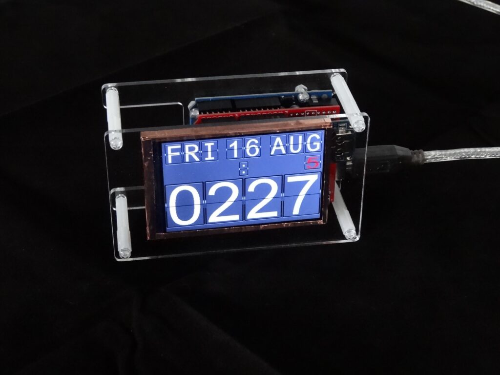
Although flip clocks may be extremely interesting electromechanical devices, with rolling flaps to show what time it is, they’re also fairly complicated if you want to build one yourself. Mark Wilson, however, took a different approach with his project, simulating the output on a 320×240 LCD display.

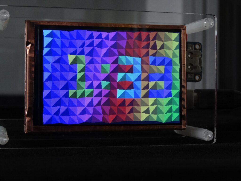
The clock is powered by an Arduino Uno and a DS3231 RTC module, allowing it to show the time, date, a blinking colon, and even the days until the trash/recycling needs to be put out. Alternate screens are available as well, including a Pong clock, triangle clock, and cube clock, which can be individually selected or set to randomly cycle if you so desire. 

For its housing, Wilson chose a minimal acrylic/standoff design that seems to suit it well, and you can see it in action in the short demo clip below.

Universal Remote a Grove Infrared project


Description

This project will convert an ordinary Keyes infra-red (IR) remote
into a programmable universal remote.

 
A single button press on the Keyes remote will be converted into precise Sony IR signal combinations using an Arduino UNO and an assortment of Seeedstudio Grove modules.
You can assign signal combinations from more than one remote if desired.
An example combination could be to:
  • Turn on the TV and then switch channels.
  • Turn on the TV, sound system, and air-conditioner.
  • Turn up the volume x 3.
With only one button press of the Keyes remote, the entire cascade of Sony signals ensues. This project can be customised for other IR methodologies, however, you may have to modify the Arduino code to accommodate them.


Parts Required

  1. Arduino Uno (or compatible board)
  2. Grove Base Shield (v2)
  3. Grove Infrared Receiver
  4. Grove Infrared Emitter
  5. Grove Button
  6. Grove 16x2 LCD (White on Blue)
  7. Grove Universal 4 pin buckled cable: one supplied with each module.
  8. KEYES IR Remote Control
  9. SONY IR remote control
  10. USB cable - to power and program the Arduino
  11. Battery pack / Power bank


More information about the Grove modules can be found here:

**Please Note: The Grove Base shield has 14 pins on the Analog side, and 18 pins on the digital side. Check the number of pins on your Arduino UNO (or compatible board) to ensure the shield will sit nicely on top. NOT compatible with Arduino boards that have the Arduino Duemilanove pin header layout.


Arduino IDE

While there are many Arduino IDE alternatives out there, I would recommend that you use the official Arduino IDE for this project. I used the official Arduino IDE app (v1.8.5) for Windows 10.
Make sure to get the most up-to-date version for your operating system here.


Libraries required

The following libraries will be used in the Arduino code:

  1. Wire Library
  2. IRLib2 Library
  3. rgb_lcd Library

Wire Library

The Wire library is used for I2C communication for the Grove LCD screen and is built into the Arduino IDE - no additional download required for this library.
 

IRLib2 Library

The IRLib2 Library is actually a "set" of IR libraries, which can be downloaded from GitHub - here. In this project, I will be transmitting and receiving NEC and Sony IR remote signals.
The required libraries (within the set) will be:
  • IRLibRecv.h
  • IRLibDecodeBase.h
  • IRLibSendBase.h
  • IRLib_P01_NEC.h
  • IRLib_P02_Sony.h
  • IRLibCombo.h
Please see the IRLib2 GitHub Page for installation instructions.
 

rgb_lcd Library

The rgb_lcd.h library simplifies the operation of the LCD screen.
Download the rgb_lcd.h library from GitHub. Install the rgb_lcd.h library ZIP file into the Arduino IDE:
  1. Load the Arduino IDE
  2. Navigate to Sketch >Include library > Add .ZIP library...
  3. Select the downloaded zip file from GitHub, and press the "Open" button
  4. Check that it installed correctly by navigating to File > Examples > Grove-LCD RGB Backlight


Arduino Code

It is always best to upload the Arduino code to the board before you make any of the connections. This way you prevent the Arduino from sending current to a component accidentally. The code is available on my GitHub repository. Or you can have a look below. This code was written for an Arduino UNO, and may need to be modified if you are using a different board.


Connection instructions

If you are using the Grove Base Shield (v2). The connections are extremely simple. Use the following table as a guide. Please note that the code above assumes the following connections.


As per the table above, you would use a Grove universal 4-pin buckled cable and connect one side to D2 on the Grove base shield, and the other side would connect to the Grove Infrared Emitter.
D3 on the base shield would connect to the Grove Infrared Receiver, and so on.
You can connect the 16x2 LCD module to ANY of the four I2C connectors on the Grove base shield.

If you do not have a Grove Base shield, you have the option to use female-to-male jumper wires (together with a breadboard). But it is easier just to get the base shield and use the universal connectors.


Project Explained

When you apply power to the Arduino, the first thing that appears on the LCD screen is:


After pressing the Grove button (connected to D5), it displays the following message:


This is the cue to press and send a signal from the Keyes remote to the Infrared receiver (which is connected to D2). The Arduino will decode the Keyes remote signal, store the value in an array, and display the signal briefly on the LCD. The LCD should now show a message:


This message is a cue to press and send the FIRST signal from the Sony remote to the Infrared receiver. The Arduino will decode and store the Sony remote signal in a different array, and display it briefly on the LCD. You have the option to send a maximum of THREE Sony signal combinations to the Infrared receiver at this step in the process. The minimum number of Sony signals you can send is zero. The way to tell the Arduino that you do not want to send any further Sony signals to the receiver in this step, is by pressing the Grove Button (connected to D5).
 
The Arduino is programmed to receive a total of 5 Keyes signals, and each signal can be paired with a maximum of 3 Sony signal combinations. Once you have recorded all of the signal combinations, you will get a message:


The Arduino will now enter the final "Universal remote mode". In this mode, it will listen out for ANY of the 5 Keyes IR remote signals recorded previously, and will send the associated Sony signal combination in return. For example, if you press the number 1 on the Keyes remote, you could potentially have it so that the Arduino will transmit a Sony signal combination to turn on the TV and jump to a specific channnel.
 
The LCD will display each of the signals being transmitted. You will know you are in "Universal remote" mode because the LCD will display:


While you may be tempted to throw your Sony remote away at this stage (because you no longer have a use for it)... I would hold on to it just in case. The signals are not stored permanently. They disappear when the Arduino is powered off. But it doesn't have to be that way. You can easily modify the code to store it in eeprom memory or something.
 
That is not the only thing you can change.Technically, you could record the signal for any remote, however, you may need to include additional libraries or code to accommodate the alternate remote symbology. You can also modify the text messages on the LCD screen to make more sense to you. The LCD can only display 16 characters per row. So keep that it mind, when you come up with creative captions.
 
I would also like to mention the reason I chose not to use Seeedstudio's IR library, was because it took up too much memory. Their library probably accommodates for a wide range of symbologies. I chose the IRLib2 Library because I could select only the symbologies that I used (Sony and NEC). Thereby reducing the total amount of memory necessary to run the project. In fact, I have been finding that many of Seeedstudio's libraries to be very memory hungry. I originally wanted to create a gesture controlled remote. But the library combinations eliminated that possibility due to the cumulative memory requirements.


Conclusion

The IRLib2 library is the key to the success of this project. Without that library, this project would have been ten times harder. I was quite amazed by the effectiveness of this record / playback technique. It felt very weird to be operating my SONY TV with a cheap and nasty Keyes remote. It was quite surreal. While I chose to control my TV in this way, I could have just as easily recorded signals from one of my other remotes that use infrared signals. As more and more devices become controllable by remotes, the more I will consider turning this project into a permanent fixture in my house. A gesture controlled remote would have been nice, however, it looks like I will have to find some other use for that module now.

If you found this tutorial helpful, please consider supporting me by buying me a virtual coffee/beer.

$3.00 AUD only
 

Social Media

You can find me on various social networks:

Follow me on Twitter: ScottC @ArduinoBasics.
I can also be found on Instagram, Pinterest, and YouTube.
And if all else fails, I have a server on Discord.


Driving a Controllerless LCD With the Humble Arduino Uno

These days, you could be forgiven for thinking driving an LCD from a microcontroller is easy. Cheap displays have proliferated, ready to go on breakout boards with controllers already baked in. Load up the right libraries and you’re up and running in a matter of minutes. However, turn your attention to trying to drive a random LCD you’ve yanked out of a piece of old equipment, and suddenly things get harder. [Ivan Kostoski] was in just such a position and decided to get down to work.

[Ivan]’s LCD was a 320×240 STN device salvaged from an old tape library. The display featured no onboard controller, and the original driver wasn’t easily repurposed. Instead, [Ivan] decided to drive it directly from an Arduino Uno.

This is easier said than done. There are stringent timing requirements that push the limits of the 8-bit platform, let alone the need for a negative voltage to drive the screen and further hardware to drive the backlight. These are all tackled in turn, with [Ivan] sharing his tips to get the most flexibility out of the display. Graphics and text modes are discussed, along with optimizations that could be possible through the varied use of available RAM and flash.

The code is available on Github. If you need inspiration for your own controllerless LCD driver. [Ben Heck] has done similar work too, using FPGA grunt to get the job done.

Spooky Animated Eyes for Your Frightening Needs

Unless you have an incredibly well-stocked parts bin, it’s probably too late to build these spooky animated eyes to scare off the neighborhood kiddies this year. But next year…

It’s pretty clear that Halloween decorating has gone over the top recently. It may not be as extreme as some Christmas displays, but plenty of folks like to up the scare-factor, and [wermy] seems to number himself among those with the spirit of the season. Like Christmas lights, these eyes are deployed as a string, but rather than just blink lights, they blink creepy eyes from various kinds of creatures. The eyes are displayed on individual backlit TFT-LCD displays housed in 3D-printed enclosures. Two pairs of eyes can be driven by the SPI interface of one ItsyBitsy M0 Express; driving more displays works, but the frame rate drops to an unacceptable level if you stretch it too far. Strung together on scraps of black ethernet cable, the peepers can live in the shrubs next to the front door or lining the walk, and with surprisingly modest power needs, you’ll get a full night of frights from a USB battery bank.

We like the look of these, and maybe we’ll do something about it next year. If you’re still in the mood to scare and don’t have the time for animated eyes this year, try these simple Arduino blinky eyes for a quick hit.

Thanks to [baldpower] for the treat. No tricks.

Hack a Day 31 Oct 16:30

The Other Kind of Phone Hacking

While it’s true that your parts bin might have a few parts harvested from outdated devices of recent vintage, there’s not much to glean anymore aside from wall warts. But the 3×48-character LCD from [Kerry Wong]’s old Uniden cordless landline phone was tempting enough for him to attempt a teardown and reverse engineering, and the results were instructive.

No data sheet? No problem. [Kerry] couldn’t find anything out about the nicely backlit display, so onto the logic analyzer it went. With only eight leads from the main board to the display module, it wasn’t likely to be a parallel protocol, and the video below shows that to be the case. A little fiddling with the parameters showed the protocol was Serial Peripheral Interface, but as with other standards that aren’t exactly standardized, [Kerry] was left with enough ambiguity to make the analysis interesting. Despite a mysterious header of 39 characters, he was able in the end to drive the LCD with an Arduino, and given that these phones were usually sold as a bundle with a base and several handsets, he ought to have a nice collection of displays for the parts bin.

With how prevalent this protocol has gotten, [Kerry]’s post makes us want to get up to speed on the basics of SPI. And to buy a logic analyzer too.


Filed under: misc hacks, teardown

A Dual-purpose Arduino Servo Tester

RC flying is one of those multi-disciplinary hobbies that really lets you expand your skill set. You don’t really need to know much to get started, but to get good you need to be part aeronautical engineer, part test pilot and part mechanic. But if you’re going to really go far you’ll also need to get good at electronics, which was part of the reason behind this Arduino servo tester.

[Peter Pokojny] decided to take the plunge into electronics to help him with the hobby, and he dove into the deep end. He built a servo tester and demonstrator based on an Arduino, and went the extra mile to give it a good UI and a bunch of functionality. The test program can cycle the servo under test through its full range of motion using any of a number of profiles — triangle, sine or square. The speed of the test cycle is selectable, and there’s even a mode to command the servo to a particular position manually. We’ll bet the build was quite a lesson for [Peter], and he ended up with a useful tool to boot.

Need to go even further back to basics than [Peter]? Then check out this primer on servos and this in-depth guide.

[via r/Arduino]


Filed under: Arduino Hacks, misc hacks
Hack a Day 23 Nov 19:31

oCat is a real-time tracker for popular cat videos

Over the last couple of years, cat videos have become the undisputed champions of the web. Whether it’s kittens playing with their shadows to failed jump attempts to giving each another massages, we’re all guilty of watching a few of these clips from time to time (yes, even at work). Built with this in mind, oCat is a real-time tracker for feline-related activity on the Internet.

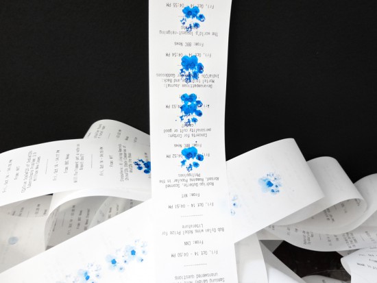
oCat consists of two parts: the oCat News Distractor and the Kitty o’Cat Twitter bot. Using Google’s YouTube API, the system works by continuously monitoring for new uploads, the number of new views each day, or a specific video that has received a remarkable amount of attention. It then tweets these stats and prints them out on thermal paper, stamping a paw print on the timeline for every 1,000 views.

Created by Annika Engelhardt, a digital media design master’s student at the University of the Arts in Bremen, oCat uses an Arduino along with an ESP Wi-Fi module, a servo, and an LCD screen. The aim of the project is to increase and reveal the amount of hours people spend watching cat videos online.

The cat is an altered Maneki-neko, holding a stamp using welding wire and hot glue. Even though I filled the stamp with extra ink, it did not work properly and I had to cut out the paw-shape from a sponge and glue it onto the original stamp.

The thermal printer used in the device needs a USB connection, so I used a Raspberry Pi to control it. I wrote a Python script that checks four different RSS news feeds for new posts every 15 minutes and prints one headline with a timestamp every minute.

The Twitter bot was programmed using Python and a library called tweepy. Most of the script is reading JSON files, juggling and comparing data and text files and in the end mixing up parts of a sentence to form a tweet. The bot will be enhanced in the future

Engelhardt exhibited the project at Galerie Flut in Bremen back in October. You can find more pictures and information on the project here.

Arduino Blog 09 Nov 05:49
api  arduino  cat  esp8266  featured  genuino  lcd  servo  wifi  youtube  

Fun Audio Waveform Generator Is More Than The Sum Of Its Parts

[Joekutz] wanted to re-build an audio-rate function generator project that he found over on Instructables. By itself, the project is very simple: it’s an 8-bit resistor-ladder DAC, a nice enclosure, and the rest is firmware.

[Joekutz] decided this wasn’t enough. He needed an LCD display, a speaker, and one-hertz precision. The LCD display alone is an insane hack. He reverse-engineers a calculator simply to use the display. But instead of mapping each key on the calculator and typing each number in directly, he only taps the four 1, +, =, and clear keys. He can then enter arbitrary numbers by typing in the right number of ones and adding them up. 345 = 111 + 111 + 111 + 11 + 1. In his video, embedded below, he describes this as a “rather stupid” idea. We think it’s hilarious.

The meat of the project is the Arduino-based waveform generator, though. In the second video below, [joekutz] walks through the firmware in detail. If you’d like a simple introduction to DDS, check it out (or read up our more in-depth version).

He also makes custom detents for his potentiometers so that he can enter precise numerical values. These consist of special knobs and spring-clips that work together to turn a normal pot into a rough 8-way (or whatever) switch. Very cool.

So even if you don’t need an R-2R DAC based waveform generator, go check this project out. There’s good ideas at every turn.


Filed under: Arduino Hacks

Animated Progress Bar Shows LCD New Tricks

A small LCD screen can be extremely helpful with small microcontroller projects. Not everything needs to communicate to a fancy server using an ESP8266. However, if the simplicity of the character displays irks you, it’s possible to spice them up a little bit with custom characters and create animations, like [Fabien] did with his animated Arduino progress bar. (Google Translate from French)
The project started out simply enough: all [Fabien] needed was a progress bar. It’s easy enough to fill in the “characters” on the 2×16 character LCD screen one-by-one to indicate progress, and the first version of this did exactly that. The second version got a little bit fancier by adding a border around the progress bar and doubling its resolution, but the third version is where knowing the inner machinations of the microcontroller really paid off. Using a custom charset reuse optimization, [Fabien] was able to use 19 custom characters at a time when the display will normally only allow for eight. This was accomplished by placing the custom characters in memory in the correct order, to essentially trick the microcontroller into displaying them.
These types of microcontroller hacks get deep into the inner workings of the microcontroller and help expose some tricks that we can all use to understand their operation on a deeper level. Whether you’re using PWM to get a microcontroller to operate a TV, or creating the ATtiny-est MIDI synth, these tricks are crucial to getting exactly what you want out of a small, inexpensive microcontroller.

Filed under: Microcontrollers