Posts with «i2c» label

Clock super-display

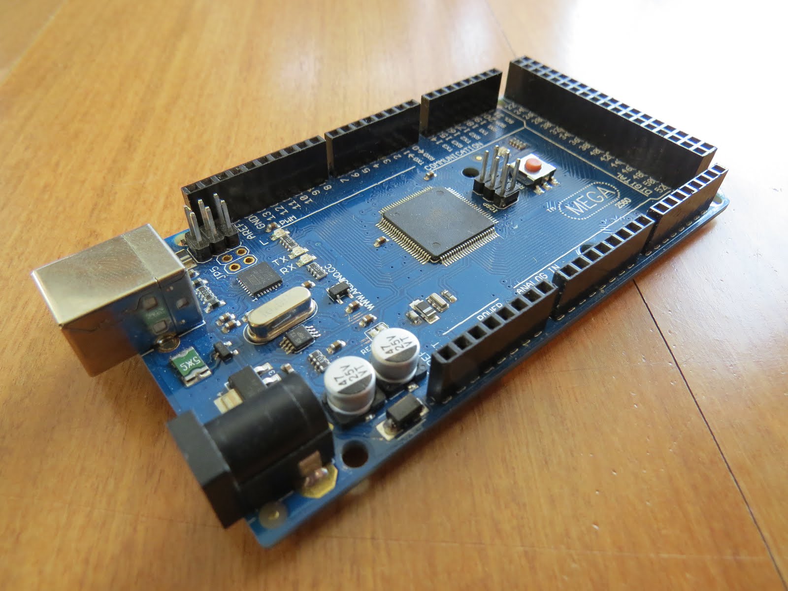
Today was a good day. In typical fashion, I started a few new "projects" almost in the same time. First one, it's assembling of a new kind of clock, from a kit sent by Nick S. I got stuck pretty early though, so I "parked" it for now. Details to come soon, in a special post.

Second one, an "Adler 121PD" vintage calculator with a VFD display, that I found "in the dumpster" (well, not really, but the idea is the same, I got it for free). I was going to break it apart, for the display and the circuitry, but I gave up when I powered it up (with an improvised cable; the original, proprietary one, was missing) and it actually worked! I may still go ahead with dis-assembling it, since it is not a great value anyway; I checked prices on ebay, and they go for around $20.

Lastly, the project that gave the name of this post: a clock LED super-display, consisting of 3 individual and independent indicators, inspired by the Leitch studio clock, brought to my attention by Nick (VE2HOT). The goal for the clock super-display is to eventually be able to emulate the Leitch clock. Here it is, in its incipient glory (only the back panel; the black wooden frame not pictured):


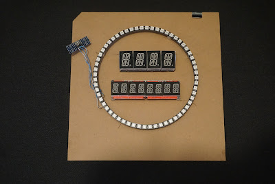
Since I am not the crafty kind-of-guy (also not keen on spending for form more than for content), I am always looking for cheap, easy and quick solutions for encasing electronics. In this case, Ikea's Ribba 9"x9" frame ($10) seems to be a good fit for the job, and hopefully will help the future clock look "Leitchy" or even better (Nick's photo below):


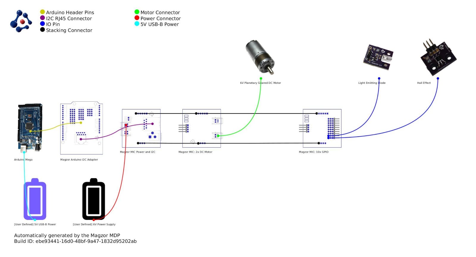
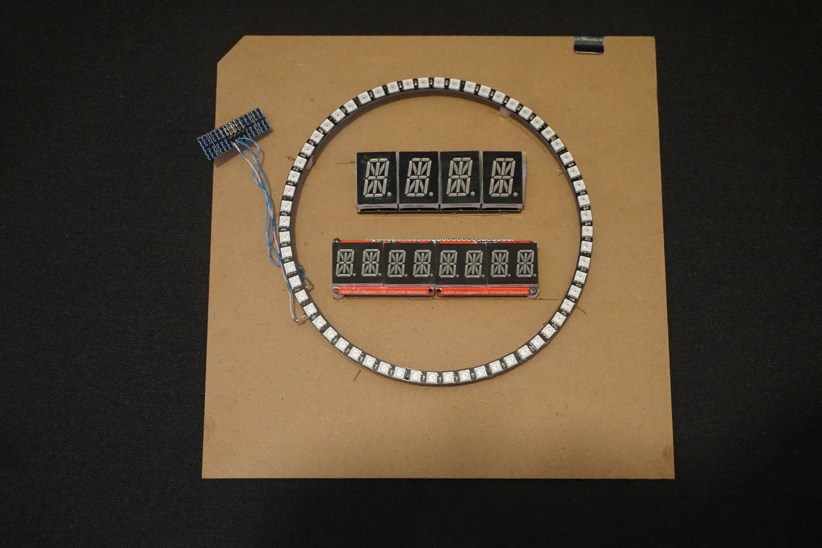
The 2 alphanumeric displays (4 and 8 chars) of the clock super-display are I2C-driven. The 60 LED ring is adafruit neopixel, controlled by a single pin. With this setup, even an ESP8266 module could be used as the brains of the clock.

The ring is fixed to the cardboard back/panel of the deep Ikea frame with four M3 plastic standoffs glued to the PCB.
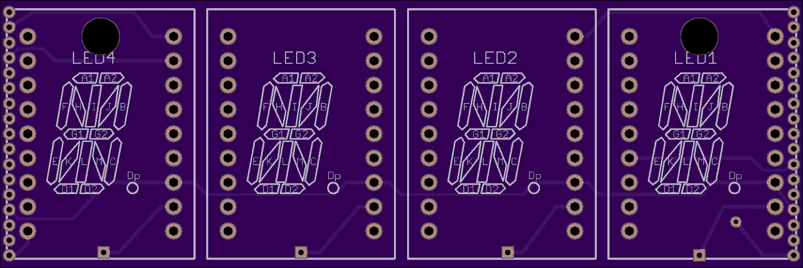
The 4-character alphanumeric 16-segment is my creation, introduced earlier. It is driven by the HT16K33 backpack, also from adafruit (not in the picture). The PCB has M3 holes for screws.
The 8-character alphanumeric is made of two side-by-side quad 14-segment LED displays, also from adafruit. The 2 modules already have the HT16K33 drivers installed (soldered on the back). Attaching these quad displays to the panel is not easy, since the holes are probably M1.4. Even these thin M1.4 screws need to be forced, because the screw head presses against display's plastic enclosure. Eventually, the M1.4 screws will be glued to the M3 plastic standoffs, that's the best I could come up with. It is weird that, for such a popular and successful product, one cannot find photos (or instructions) on mounting these modules using screws.

Next step is the software support in the WiFiChron software. Also need to find a way to access the 3 buttons: having them in the back is not a good idea, having them in the front is impossible, unless the glass is replaced with transparent/smoky/grey acrylic, which can be drilled.

Wise time with Arduino 11 May 02:13
esp8266  hdsp  i2c  wifichron  

WiFiChron support for 16-segment LED display

This is the second time I am writing this post. First time it just disappeared after almost 2 hours of editing. I started the post by saying that whenever I want to have some electronics fun, I open one of my drawers. Nice story line, but I am too frustrated now to recreate it from memory. (The lesson I learned is that I should write it first as a document, save locally, then copy and paste into a blog post.)
So I will keep it short and dry.

Some time ago, I designed this "4-character 16-segment 1-inch LED" board (pictured below), briefly mentioned here. I abandoned it, after a couple of failed tries, while writing the character definitions. Since then, I discovered the Adafruit 4-char alphanumeric LED backpack, which comes with nice software support as well.


For WiFiChron, two cascaded modules make an 8-character display functionally similar to HDSP-2534, but bigger and more visible. With the "Display Abstraction Layer" already in place, software support should be easy to integrate, since controlling it with the HT16K33 breakout allows the re-use of the above mentioned Adafruit LED backpack library. For maximum compatibility, I followed the same wiring, then connected the two extra segments, A2 and D2, to pin 10 (not connected for the 14-segment backpack) and pin 11 (connected to the DP), respectively.


I added a new class, Alphanum8x16, to the original files (Adafruit_LEDBackpack.h and cpp) to control the extra segments:


class Alphanum8x16 : public Adafruit_AlphaNum4
{
 public:
  void writeDigitAscii(uint8_t n, uint8_t ascii);
};


void Alphanum8x16::writeDigitAscii(uint8_t n, uint8_t a)
{
  uint16_t font = pgm_read_word(alphafonttable+a);
  displaybuffer[n] = font;

  //--------------------------------------------------------
  // this is the Adafruit mapping of digits to segments:
  // 0 DP N M L K J H G2 G1 F E D C B A
  //
  // this is the 16 seg mapping of digits to segments:
  // A2 D2 N M L K J H G2 G1 F E D1 C B A1
  //
  // bits:
  // 1  1  1 ...                 ...  1 0
  // 5  4  3
  //
  // Note: DP is not connected/controlled for the 16 seg;
  //--------------------------------------------------------

  // if A1 (bit 0) is on, set A2 (bit 15) as well;
  if (font & 1)
    displaybuffer[n] |= 0x8000;

  // if D1 (bit 3) is on, set D2 (bit 14) as well;
  if (font & 8)
    displaybuffer[n] |= 0x4000;
}

The 8x16-segment display is implemented in class DisplayHT16K33 in the WiFiChron software.
So far, WiFiChron can support the following displays (defines in DAL.h):

//#define DISPLAY_HDSP2534
//#define DISPLAY_DL1414
#define DISPLAY_HT16K33
//#define DISPLAY_OLED
//#define DISPLAY_HT1632
//#define DISPLAY_MAX6955

In principle, any display that can show 8 characters can be used through DAL.


Wise time with Arduino 14 Apr 02:15
hacking  hdsp  i2c  wifichron  

Arduino and Pi Share Boardspace

A Raspberry Pi Zero (W) and Arduino are very different animals, the prior has processing power and connectivity while the latter has some analog to digital converters (ADCs) and nearly real-time reactions. You can connect them to one another with a USB cable and for many projects that will happily wed the two. Beyond that, we can interface this odd couple entirely through serial, SPI, I2C, and logic-level signaling. How? Through a device by [cburgess] that is being called an Arduino shield that supports a Pi0 (W). Maybe it is a cape which interfaces with Arduino. The distinction may be moot since each board has a familiar footprint and both of them are found here.

Depending on how they are set up and programmed, one can take control over the other, or they could happily do their own thing and just exchange a little information. This board is like a marriage counselor between a Raspberry Pi and an Arduino. It provides the level-shifting so they don’t blow each other up and libraries so they can speak nicely to one another. If you want to dig a bit deeper into this one, design files and code examples are on available.

Perhaps we’ll report on this board at the heart of a pinball machine retrofit, a vintage vending machine restoration, or maybe a working prop replica from the retro bar in Back to the Future II.

Arduino Gets a Command Line Interface

When using an Arduino, at least once you’ve made it past blinking LEDs, you might start making use of the serial connection to send and receive information from the microcontroller. Communicating with the board while it’s interacting with its environment is a crucial way to get information in real-time. Usually, that’s as far as it goes, but [Pieter] wanted to take it a step farther than that with his command line interpreter (CLI) for the Arduino.

The CLI allows the user to run Unix-like commands directly on the Arduino. This means control of GPIO and the rest of the features of the microcontroller via command line. The CLI communicates between the microcontroller and the ANSI/VT100 terminal emulator of your choosing on your computer, enabling a wealth of new methods of interacting with an Arduino.

The CLI requires a hex file to be loaded onto the Arduino that you can find at a separate site, also maintained by [Pieter]. Once that’s running, you can get all of that sweet command line goodness out of your Arduino. [Pieter] also has some examples on his project page, as well as the complete how-to to get this all set up and running. There’s a lot going on in the command line world, in Linux as well as windows. So there’s plenty to explore there as well.

Hack a Day 11 Nov 03:00
arduino  cli  command line  gpio  i2c  microcontrollers  serial  shell  unix  uno  

Doing Logic Analysis To Get Around The CatGenie’s DRM

The CatGenie is an amazing device to watch in action, basically a self-cleaning litter box for cats that even does away with the need to replace the litter. It’s comparable to what the indoor flush toilet is for humans compared to maintaining a composting toilet. However, there is a problem. It uses costly soap cartridges which have to be replaced because an RFID reader and a usage counter prevent you from simply refilling them yourself.

CatGenie and Arduino

[David Hamp-Gonsalves] reverse engineered the electronics so that he didn’t have to pay for the cartridges anymore. This has been done before and one of those who did it created a product called the CartridgeGenius, but it’s made and sold as a parttime project and there were none in stock. The cartridges have an RFID tag and another solution which we’ve covered before is to replace the RFID reader board with an Arduino. That’s the solution [David] adopted. So why write this post if this isn’t new?

The RFID reader board communicates with the rest of the CatGenie using I2C and he needed to know what was being transmitted. To do that he learned how to use a cheap logic analyzer to read the signals on the I2C wires, which makes this an interesting story. You can see the logic analyser output on his blog and GitHub repository along with mention of a timing issue he ran into. From what he learned, he wrote up Arduino code which sends the same signals. He and his cat are now sitting pretty.

What he didn’t do is make a video. But the CatGenie really is amazing to watch in action as it goes through its rather complex 30-35 minute process so we found a video of it doing its thing, shown at 3.5x speed, and included that below.  If you’re into that sort of thing.

[via Adafruit]

Hack a Day 04 Sep 09:00

A Crash Course In Reliable Communication

It’s probably fair to say that anyone reading these words understands conceptually how physically connected devices communicate with each other. In the most basic configuration, one wire establishes a common ground as a shared reference point and then the “signal” is sent over a second wire. But what actually is a signal, how do the devices stay synchronized, and what happens when a dodgy link causes some data to go missing?

All of these questions, and more, are addressed by [Ben Eater] in his fascinating series on data transmission. He takes a very low-level approach to explaining the basics of communication, starting with the concept of non-return-to-zero encoding and working his way to a shared clock signal to make sure all of the devices in the network are in step. Most of us are familiar with the data and clock wires used in serial communications protocols like I2C, but rarely do you get to see such a clear and detailed explanation of how it all works.

He demonstrates the challenge of getting two independent devices to communicate, trying in vain to adjust the delays on the receiving and transmitting Arduinos to try to establish a reliable link at a leisurely five bits per second. But even at this digital snail’s pace, errors pop up within a few seconds. [Ben] goes on to show that the oscillators used in consumer electronics simply aren’t consistent enough between devices to stay synchronized for more than a few hundred bits. Until atomic clocks come standard on the Arduino, it’s just not an option.

[Ben] then explains the concept of a dedicated clock signal, and how it can be used to make sure the devices are in sync even if their local clocks drift around. As he shows, as long as the data signal and the clock signal are hitting at the same time, the actual timing doesn’t matter much. Even within the confines of this basic demo, some drift in the clock signal is observed, but it has no detrimental effect on communication.

In the next part of the series, [Ben] will tackle error correction techniques. Until then, you might want to check out the fantastic piece [Elliot Williams] put together on I2C.

[Thanks to George Graves for the tip.]

Push it to the Limit: SSD1306 at 150 FPS

A good deal of the projects we cover here at Hackaday are not, in the strictest sense, practical endeavors. If we required that everything which graced our digital pages had a clear end result, the site would be in a rather sad state of affairs. Sometimes it’s enough just to do something for the challenge of it. But more often than not, you’ll learn something in the process which you can use down the line.

That’s precisely what pushed [Laurence Bank] to see how well he could optimize the frame rate on the popular SSD1306 OLED display. After several iterations of his code, he was able to achieve a blistering 151.5 FPS, with apparently still some room for improvement if he’s feeling up to the challenge. But considering his first attempt was only running at 5.5 FPS, we’d say he’s already more than earned his hacker cred on this one.

A few different tricks were used to achieve such incredible performance gains. To start with, while the official I2C specification says you’re supposed to wait for an acknowledgment back from the device when communicating with it, [Laurence] realized the SSD1306 didn’t actually care. He could continuously blast commands at the display without bothering to wait for an acknowledgment. He admits there are problems with this method, but you can’t argue with the results.

To really wring all the performance out of the system he could, [Laurence] donned his Assembly Cap and examined how the Arduino IDE compiler was interpreting his code. He identified a few areas where changing his C code would force the compiler to generate faster output. He notes that this wouldn’t normally be required when working with more advanced compilers, but that the Arduino toolchain needs its hand held occasionally.

This isn’t the first time we’ve seen somebody try and push more pixels through the very same OLED display, and it’s interesting to see the two very different approaches to the same goal.

DIY I2C Devices with ATtiny85

[Pawel] has a weather station, and its nerve-center is a Raspberry Pi. He wanted to include a light sensor but the problem is, the Pi doesn’t have a built-in ADC to read the voltage off the light-dependent resistor that he (presumably) had in his junk box. You can, of course, buy I2C ADC chips and modules, but when you’ve already got a microcontroller that has ADC peripherals on board, why bother?

[Pawel] wired up a tremendously simple circuit, downloaded some I2C slave-mode code, and added an LED for good measure. It’s all up on GitHub if you’re interested.

Bright by Day, Dark by Night!

We’re covering this because we rarely see people coding for I2C slave devices. Everyone and their mom uses I2C to connect to sensors, for which the Arduino “Wire” library or “i2c-tools” on the Pi do just fine. But what do you do when you want to make the I2C device? [Pawel]’s project makes use of TinyWireS, a slave-mode SPI and I2C library for AVR ATtiny Arduino projects.

Here, [Pawel] just wanted a light sensor. But if you’re building your own devices, the sky is the limit. What’s the most esoteric I2C sensor that you can imagine? (And is it really the case that we haven’t seen an I2C slave device hack since 2010?)


Filed under: ATtiny Hacks
Hack a Day 07 Nov 09:00

Three Arduinos, Sixteen Square Waves

[Folkert van Heusden] sent us in his diabolical MIDI device. Ardio is a MIDI synthesizer of sorts, playing up to sixteen channels of square waves, each on its separate Arduino output pin, and mixed down to stereo with a bunch of resistors. It only plays square waves, and they don’t seem to be entirely in tune, but it makes a heck of a racket and makes use of an interesting architecture.

Ardio is made up of three separate el cheapo Arduino Minis, because…why not?! One Arduino handles the incoming MIDI data and sends note requests out to the other modules over I2C. The voice modules receive commands — play this frequency on that pin — and take care of the sound generation.

None of the chips are heavily loaded, and everything seems to run smoothly, despite the amount of data that’s coming in. As evidence, go download [Folkert]’s rendition of Abba’s classic “Chiquitita” in delicious sixteen-voice “harmony”. It’s a fun exercise in using what’s cheap and easy to get something done.


Filed under: musical hacks
Hack a Day 03 Aug 16:30
arduino  i2c  midi  music  musical hacks  

Arduino Stroboscope Animation


UPDATE: Magzor has just started a Kickstarter campaign. Please check it out to get a good package deal on many of their components. Many of which were used in this tutorial.
 
This tutorial will show you how to build your own Stroboscopic Animator using Magzor's Mechanotronic Design Portal as a starting point. Magzor Corporation is a business in California that is trying really hard to simplify robotic design. They want to enable users with little to no engineering experience to design and manufacture a custom robot by themselves in a matter of hours.
What is a stroboscope? A stroboscope is an instrument that uses a strobe light to make a moving object look stationary… We will use this feature to create an interesting 4 picture animation on a rotating disk.


Have a look at the video below to see the project in action, and the MDP process walk-through:


Video


Parts Required:


Magzor Schematic Diagram

Click to zoom ...

 
Further build instructions can be obtained by selecting the components in the Mechanotronics Design Portal within the Magzor website. Generating the build, and then selecting "Setup Instructions" tab at the top of the page. See video above to see this process in action.


Arduino Sketch


Make sure to copy and paste the following code into your Arduino IDE. It doesn't seem to work directly from the browser. You also need to install the Arduino Magzor I2C library ( http://magzor.com/downloads/ )


Putting it together


Arduino MEGA


Magzor I2C board


MIC Boards


MIC Boards Assembled


Sensors, Modules and Shields - all put together


Motor with Bracket and Wire


Picture lined up with magnet on disk


Stroboscopic Animation


The Arduino MEGA microcontroller listens for the hall effect sensor to be triggered by the south facing side of the magnet on the underside of the rotating disk. As the magnet moves over the hall effect sensor, the sensor is triggered and the Arduino instructs the LED to blink for a fraction of a second. By manipulating the delay after the trigger time, we can get the LED to blink when one of the four images on the rotating disk is towards the front position. And if we get the timing right, we can make a simple animation.
 
If you watch the video above, you will see that the image bounces around a little bit. The duration of each frame is determined by the speed of the rotating disk (or motor), and the number of LED flashes per frame. Any changes in rotation speed will affect the position of the picture when the LED blinks. My rotating disk is not completely semetrical or centred correctly, and therefore a bit jumpy… but you get the idea. Bold images with high contrast seem to work best… Precision is key for this type of project. And if you can get the disk to rotate at a constant speed, you could probably do away with the hall effect sensors and magnets… however, in my case, these were essential in getting the project to work as intended.
 
This project is a lot of fun. You can really get creative by making your own pictures or 3 dimensional models (for a stop motion effect). Try different colours. It really is quite cool.


Concluding Comments


I would like to thank Magzor for supplying the components used in this tutorial, and letting me try out their MDP process. I really like the concept, the one stop shop which looks after you from beginning to end. Providing everything I needed to get the project off the ground. The point of this exercise was to go through the entire process of selecting the parts, build the project, and get it up and running. And I have done that in no time at all.
 
There is only one library to download and install, and the good thing is that you don't have to go hunting for it. The latest "correct" working version of the library is easy to find, right there on the Magzor website… Speaking of the Magzor website, please make sure to take a quick look around. It is quite impressive.
 
  UPDATE: Magzor has just started a Kickstarter campaign. Please check it out to get a good package deal on many of their components. Many of which were used in this tutorial.


If you like this page, please do me a favour and show your appreciation :

 
Visit my ArduinoBasics Google + page.
Follow me on Twitter by looking for ScottC @ArduinoBasics.
I can also be found on Pinterest and Instagram.
Have a look at my videos on my YouTube channel.


This project would not have been possible without the collaborative effort from Magzor Corporation.
Please visit their site and check out the MDP.


However, if you do not have a google profile...
Feel free to share this page with your friends in any way you see fit.