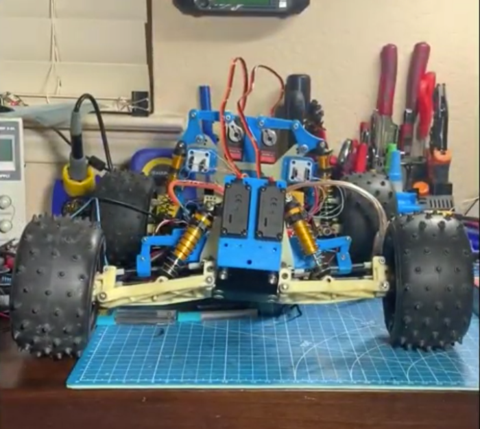
Active suspensions are almost a holy grail for cars, adding so much performance gain that certain types have even been banned from Formula 1 racing. That doesn’t stop them from being used on a wide variety of luxury and performance cars, though, as they can easily be tuned on the fly for comfort or improved handling. They also can be fitted to remote controlled cars as [Indeterminate Design] shows with this electronic servo-operated active suspension system for his RC truck.
Each of the four servos used in this build is linked to the mounting point of the existing coilover suspension on the truck. This allows the servo to change the angle that the suspension is positioned while the truck is moving. As a result, the truck has a dramatic performance enhancement including a tighter turning radius, more stability, and the capability of doing donuts. The control system runs on an Arduino with an ESP32 to enable live streaming of data, and also includes an MPU6050 to monitor the position of the truck’s frame while it is in motion.
There’s a lot going on in this build especially with regard to the control system that handles all of the servos. Right now it’s only programmed to try to keep the truck’s body relatively level, but [Indeterminate Design] plans to program several additional control modes in the future. There’s a lot of considerations to make with a system like this, and even more if you want to accommodate for Rocket League-like jumps.
Like many of us, [Michael] needed a way to let the family know whether pants are required to enter the room — in other words, whenever a videoconference is in progress. Sure he could hang a do not disturb sign, but those are easy to forget. There’s no need to worry about forgetting to change status because this beautiful wall-mounted sign can be controlled with Alexa.
Inside the gorgeous box made from walnut, curly maple, and oak is an ESP32, some RGB LEDs, and three MOSFETs. [Michael] is using the fauxmoESP library to interface the ESP32 with Alexa, which emulates a Phillips Hue bulb for the sake of using a protocol she already knows. [Michael] can change the color and brightness percentage with voice commands.
The sign is set up as four different devices — one default, and one for each color. Since talking to Alexa isn’t always appropriate, [Michael] can also change the color of the LEDs using sliders on a website that’s served up by the ESP. Check out the full build video after the break.
When we last heard from [lixielabs] he was building Nixie tube replacements out of etched acrylic and LEDs. Well he’s moved forward a few decades to bring us the Pixie, a chainable, addressable backpack for tiny LED matrix displays.
Each Pixie module is designed to host two gorgeous little Lite-On LTP-305G/HR 5×7 LED dot matrix displays, which we suspect have been impulse purchases in many a shopping cart. Along with the displays there is a small matrix controller and an ATTINY45 to expose a friendly electrical interface. Each module is designed to be mounted edge to edge and daisy chained out to 12 or more (with two displays each) for a flexible display any size you need. But to address the entire array only two control pins are required (data and clock).
[lixielabs] has done the legwork to make using those pins as easy as possible. He is careful to point out the importance of a good SDK and provides handy Arduino libraries for common microcontrollers and a reference implementation for the Raspberry Pi that should be easy to crib from to support new platforms. To go with that library support is superb documentation in the form of a datasheet (complete with dimensions and schematic!) and well stocked GitHub repo with examples and more.
To get a sense of their graphical capabilities, check out a video of 6 Pixie’s acting as a VU meter after the break. The Pixie looks like what you get when a hacker gets frustrated at reinventing LED dot matrix control for every project and decided to solve it once and for all. The design is clean, well documented, and extremely functional. We’re excited to see what comes next!
We start this week with very sad news indeed. You may have heard about the horrific fire on the dive boat Conception off Santa Cruz Island last week, which claimed 33 lives. Sadly, we lost one of our own in the tragedy: Dan Garcia, author of the wildly popular FastLED library. Dan, 46, was an Apple engineer who lived in Berkley; his partner Yulia Krashennaya died with him. Our community owes Dan a lot for the work he put into FastLED over the last seven years, as many an addressable LED is being driven by his code today. Maybe this would be a good chance to build a project that uses FastLED and add a little light to the world, courtesy of Dan.
In happier news, the biggest party of the hardware hacking year is rapidly approaching. That’s right, the 2019 Hackaday Superconference will be upon us before you know it. Rumor has it that there aren’t that many tickets left, and we haven’t even announced the slate of talks yet. That’s likely to clean out the remaining stock pretty darn quickly. Are you seriously prepared to miss this? It seems like a big mistake to us, so why don’t you hop over and secure your spot before you’re crying into your Club-Mate and wondering what all the cool kids will be doing in November.
Of course one of the highlights of Superconference is the announcement of the Hackaday Prize winner. And while we naturally think our Prize is the best contest, that doesn’t mean there aren’t others worth entering. MyMiniFactory, the online 3D-printing community, is currently running a “Design with Arduino” competition that should be right up the alley of Hackaday readers. The goal is simple: submit a 3D-printed design that incorporates Arduino or other electronics. That’s it! Entries are accepted through September 16, so you’ve still got plenty of time.
Sometimes you see something that just floors you. Check out this tiny ESP32 board. It doesn’t just plug into a USB port – it fits completely inside a standard USB Type A jack. The four-layer board sports an ESP32, FTDI chip, voltage regulator, an LED and a ceramic antenna for WiFi and Bluetooth. Why would you want such a thing? Why wouldn’t you! The board is coming soon on CrowdSupply, so we hope to see projects using this start showing up in the tipline soon.
Here’s a “why didn’t I think of that?” bench tip that just struck us as brilliant. Ever had to probe a board to trace signal paths? It’s a common enough task for reverse engineering and repairs, but with increasingly dense boards, probing a massive number of traces is just too much of a chore. Hackaday superfriend Mike Harrison from “mikeselectricstuff” makes the chore easier with a brush made from fine stainless wires crimped into a ring terminal. Attached to one probe of a multimeter, the brush covers much more of the board at a time, finding the general area where your trace of interest ends up. Once you’re in the neighborhood you can drop back to probing one pad at a time. Genius! We’d imagine a decent brush could also be made from a bit of coax braid too.
Another shop tip to wrap up this week, this one for woodworkers and metalworkers alike. Raw materials are expensive, and getting the most bang for your buck is often a matter of carefully laying out parts on sheet goods to minimize waste. Doing this manually can be a real test of your spatial relations skills, so why not automate it with this cut list optimizer? The app will overlay parts onto user-defined rectangles and snuggle them together to minimize waste. The program takes any units, can account for material lost to kerfs, and will even respect grain direction if needed. It’s built for wood, but it should prove useful for sheet metal on a plasma cutter, acrylic on a laser, or even PCBs on a panel.
Potentially, one of the great things about having a device connected to the network is that you can update it remotely. However, how do you make that happen? If you use the Arduino setup for the ESP8266 or ESP32, you might try [scottchiefbaker’s] library which promises to make the process easy.
Adding it looks to be simple. You’ll need an include, of course. If you don’t mind using port 8080 and the path /webota, you only need to call handle_webota() from your main loop. If you want to change the defaults, you’ll need to add an extra call in your setup. You also need to set up a few global variables to specify your network parameters.
The only caveat is that long delay statements in your loop can block things from working and aren’t a great idea anyway. If you have them, you can replace all your delay calls with webota_delay which will stop the system from ignoring update requests.
The code started from a different online tutorial but packaged the code up nicely for reuse. To do an update, simply navigate to the device with a web browser and use the correct port number and path. From there you can upload a new binary image taken from the Arduino IDE with the export compiled binary command.
The only concern we saw was the code didn’t appear to authenticate you at all. That means anyone could load code into your ESP. That might be ok on a private network, but on the public Internet it is surely asking for trouble. The original tutorial code did have a hardcoded user and password, but it didn’t look very useful as the password was in the clear and didn’t stop you from uploading if you knew the right URL. Dropping it from the library probably makes sense, but we would want to build some kind of meaningful security into anything we deployed.
Today ahead of the Bay Area Maker Faire, Arduino has announced a bevy of new boards that bring modern features and modern chips to the Arduino ecosystem.
Most ambitious of these new offerings is a board that combines a fast ARM microcontroller, WiFi, Bluetooth, and an FPGA. All this is wrapped in a package that provides Mini HDMI out and pins for a PCIe-Express slot. They’re calling it the Arduino MKR Vidor 4000.
Bringing an FPGA to the Arduino ecosystem is on the list of the most interesting advances in DIY electronics in recent memory, and there’s a lot to unpack here. FPGA development boards aren’t new. You can find crates of them hidden in the storage closet of any University’s electronics lab. If you want to buy an FPGA dev board, the Terasic DE10 is a good starter bundle, the iCEstick has an Open Source toolchain, and this one has pink soldermask. With the release of the MKR Vidor, the goal for Arduino isn’t just to release a board with an FPGA; the goal is to release a tool that allows anyone to use an FPGA.
The key to democratizing FPGA development is Arduino’s work with the Arduino Create ecosystem. Arduino Create is the company’s online IDE that gives everyone the ability to share projects and upload code with Over-the-Air updates. The MKR Vidor will launch with integration to the Arduino Create ecosystem that includes a visual editor to work with the pre-compiled IP for the FPGA. That’s not to say you can’t just plug your own VHDL into this board and get it working; that’s still possible. But Arduino would like to create a system where anyone can move blocks of IP around with a tool that’s easy for beginners.
A Facelift for the Uno WiFi
First up is the brand new Arduino Uno WiFi. While there have been other boards bearing the name ‘Arduino Uno WiFi’ over the years, a lot has changed in the world of tiny radio modules and 8-bit microcontrollers over the past few years. The new Arduino Uno WiFi is powered by a new 8-bit AVR, the ATMega4809. The ATMega4809 is a new part announced just a few months ago, and is just about what you would expect from the next-generation 8-bit Arduino; it runs at 20MHz, has 48 kB of Flash, 6 kB of SRAM, and it comes in a 48-pin package. The ATMega4809 is taking a few lattices of silicon out of Microchip’s playbook and adds Custom Configurable Logic. The CCL in the new ATMega is a peripheral that is kinda, sorta like a CPLD on chip. If you’ve ever had something that could be more easily done with logic gates than software, the CCL is the tool for the job.
But a new 8-bit microcontroller doesn’t make a WiFi-enabled Arduino. The wireless power behind the new Arduino comes from a custom ESP-32 based module from u-blox. There’s also a tiny crypto chip (Microchip’s ATECC508A) so the Uno WiFi will work with AWS. The Arduino Uno WiFi will be available this June.
But this isn’t the only announcement from the Arduino org today. They’ve been hard at work on some killer features for a while now, and now they’re finally ready for release. What’s the big news? Debuggers. Real debuggers for the Arduino that are easy to use. There are also new boards aimed at Arduino’s IoT strategy.
The Future of Arduino
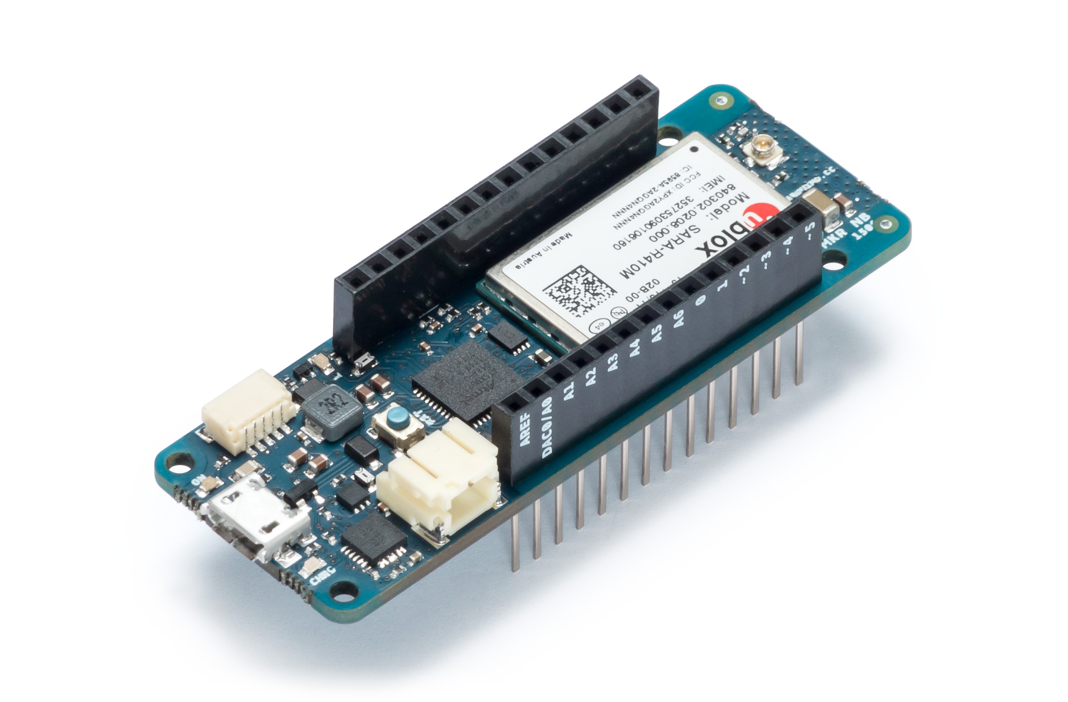
As you would expect in the world of embedded development, the future is IoT. Last week, Arduino announced the release of two new boards, the MKR WiFi 1010 and the MKR NB 1500. The MKR WiFi 1010 features a SAMD21 Cortex-M0+ microcontroller and a u-blox module (again featuring an ESP-32) giving the board WiFi. The MKR NB 1500 is designed for cellular networks and features the same SAMD21 Cortex-M0+ microcontroller found in the MKR WiFi 1010, but also adds a u-blox cellular module that will connect to LTE networks using Narrowband IoT, but the module does also support Cat M1 networks.
But IoT isn’t the only thing Arduino has been working on. On the leadup to the World Maker Faire this weekend, I had the opportunity to speak with Fabio Violante, CEO of Arduino, and Massimo Banzi, Co-founder of Arduino, and what I heard was remarkable. There’s going to be an update to the Arduino IDE soon, and real debugging is coming to the Arduino ecosystem. This is a significant development in Arduino’s software efforts, and when Fabio was appointed CEO last July, this was the first thing he wanted to do.
Also on deck for upcoming bits of hardware is a slow upgrade from ARM Cortex-M0 parts to Cortex-M4 parts. While this change isn’t exactly overdue, it is a direct result of the ever-increasing power of available microcontrollers. The reason for this change is the growing need for more compute power on embedded platforms, and simply the fact that more powerful chips are cheaper now.
Massimo, Fabio, and the rest of the Arduino team will be showing off their latest wares at Maker Faire Bay Area this weekend, and we will be posting updates. The FPGA Arduino — the MKR Vidor 4000 — will be on display running a computer vision demo, and there will, of course, be fancy new boards on hand. We’ll be posting updates so keep your eye on Hackaday!
With a GPS on every smartphone, one would be forgiven for forgetting that handheld GPS units still exist. Seeking to keep accurate data on a few upcoming trips, [_Traveler] took on a custom-build that resulted in this GPS data logger.
Keeping tabs on [_Traveler] is a Ublox M8N GPS which is on full-time, logging data every 30 seconds, for up to 2.5 days. All data is saved to an SD card, with an ESP32 to act as a brain and make downloading the info more accessible via WiFi . While tracking the obvious — like position, speed, and time — this data logger also displays temperature, elevation, dawn and dusk, on an ePaper screen which is a great choice for conserving battery.
The prototyping process is neat on this one. The first complete build used point-to-point soldering on a protoboard to link several breakout modules together. After that, a PCB design embraces the same modules, with a footprint for the ESP’s castellated edges and header footprints for USB charing board, SD card board, ePaper, etc. All of this finds a hope in a 3D printed enclosure. After a fair chunk of time coding in the Arduino IDE the logger is ready for [_Traveler]’s next excursion!
As far as power consumption in the field, [_Traveler] says the GPS takes a few moments to get a proper location — with the ESP chewing through battery life all the while — and plans to tinker with it in shorter order.
If you use the Arduino IDE to program the ESP32, you might be interested in [Andreas Spiess’] latest video (see below). In it, he shows an example of using all three ESP32 UARTs from an Arduino program. He calls the third port “secret” although that’s really a misnomer. However, it does require a quick patch to the Arduino library to make it work.
Just gaining access to the additional UARTs isn’t hard. You simply use one of the additional serial port objects available. However, enabling UART 1 causes the ESP32 to crash! The reason is that by default, UART 1 uses the same pins as the ESP32 flash memory.
Luckily, the chip has a matrix switch that can put nearly any logical I/O pin on any physical I/O pin. [Andreas] shows how to modify the code, so that UART 1 maps to unused pins, which makes everything work. it is a simple change, replacing two parameters to a call that — among other things — maps the I/O pins. You could use the technique to relocate the UARTs to other places if you choose.
If you want to learn more about the ESP32, we covered a good set of tutorials for you to check out. Or if you just want a quick overview, you can start here.
This weekend at the Bay Area Maker Faire, Arduino in conjunction with SiFive, a fabless provider of the Open Source RISC-V micros, introduced the Arduino Cinque. This is a board running one of the fastest microcontrollers available, and as an added bonus, this board includes Espressif’s ESP32, another wonderchip that features WiFi and Bluetooth alongside a very, very powerful SoC.
Details on the Arduino Cinque are slim at the moment, but from what we’ve seen so far, the Cinque is an impressively powerful board featuring the RISC-V FE310 SoC from SiFive, an ESP32, and an STM32F103. The STM32 appears to be dedicated to providing the board with USB to UART translation, something the first RISC-V compatible Arduino solved with an FTDI chip. Using an FTDI chip is, of course, a questionable design decision when building a capital ‘O’ Open microcontroller platform, and we’re glad SiFive and Arduino found a better solution. It’s unknown if this STM32 can be used alongside the FE310 and ESP32 at this point.
We’ve taken a look at SiFive’s FE310 SoC, and it is an extremely capable chip. It was released first at the HiFive1, and our hands-on testing revealed this is a chip that outperforms the current performance champ of the Arduino world, the Teensy 3.6. Of course, with any new architecture, there will be a few problems porting the vast number of libraries over to the FE310, but SiFive has included an Arduino compatible SDK. It’s promising, and we can’t wait to see SiFive’s work in more boards.
In case you missed it, the big news is that a minimal Arduino core is up and working on the ESP32. There’s still lots left to do, but the core functionality — GPIO, UART, SPI, I2C, and WiFi — are all up and ready to be tested out. Installing the library is as easy as checking out the code from GitHub into your Arduino install, so that’s exactly what I did.
I then spent a couple days playing around with it. It’s a work in progress, but it’s getting to the point of being useful, and the codebase itself contains some hidden gems. Come on along and take a sneak peek.
The Core
An Arduino isn’t worth very much unless it can talk to the outside world, and making the familiar Arduino commands work with the ESP32’s peripheral hardware is the job of the core firmware. As of this writing, GPIO, WiFi, SPI and I2C were ready to test out. GPIO means basically digitalWrite() and digitalRead() and there’s not much to say — they work. WiFi is very similar to the ESP8266 version, and aside from getting the ESP32 onto our home WiFi network, I didn’t push it hard yet. When other libraries come online that use WiFi, I’ll give it a second look.
SPI
The SPI routines in the ESP32 Arduino port both work just fine. I tested it out by connecting a 25LC256 SPI EEPROM to the chip. The ESP’s extremely flexible hardware peripheral routing matrix allows it to assign the SPI functions to any pins, but the Arduino implementation is preset to a default pinout, so you just need to look it up, and hook up MOSI to MOSI and so on. As of now, it only uses one of the ESP32’s two free SPI units.
With SPI, some of the weirdness of using Arduino on a powerful chip like the ESP32 start to poke through. To set the speed of the SPI peripheral, you can use the familiar SPI_CLOCK_DIV_XX macros, only they’re scaled up to match the ESP32’s faster CPU clock speed. The end result is that SPI_CLOCK_DIV_16 gives you a 1 MHz SPI bus on either the 16 MHz Uno or the 240 MHz ESP32, which is probably what you want for compatibility with old code. But 240 divided by 16 is not 1. In retrospect, the macros would be better defined in terms of the desired frequency rather than the division factor, but you can’t go back in time.
There were also two extra definitions that I had to add to the program to make it run, but they’ve both been streamlined into the mainline in the last eighteen hours. That’s the deal with quickly evolving, openly developed software. One day you write that the macro MSBFIRST isn’t defined, and before you can go to press, it’s defined right there in Arduino.h. Great stuff!
I2C: The Wire
The I2C (“Wire”) library has also gotten the ESP32 treatment, and worked just as it should with an LM75 temperature sensor. This is my standard I2C test device, because it lets you read a few registers by default, but you can also send the sensor a few configuration options and read them back out. It’s not a particularly demanding device, but when it works you know the basics are working. And it did.
The ESP’s dedicated I2C pins are on GPIO 21 and 22 for data and clock respectively. Some I2C implementations will use the microcontroller’s pullup resistors to pull the I2C bus lines high, so I tested that out by pulling the 10 KOhm resistors out. The ESP stopped getting data back instantly, so that answers that. Don’t forget your pullup resistors on the I2C lines and all is well. Otherwise, it’s just connecting up two wires, double-checking the I2C device address, and reading in the data. That was easy.
External Libraries
More than half of the reason to use Arduino is the wide range of external, add-on libraries that make interfacing with all sorts of hardware easy and painless. Many of these libraries are built strictly on top of the Arduino core, and should “just work”. Of course, when you’re actually coding this close to the hardware, nothing is going to be as portable as it is a few layers of abstraction higher up on your desktop computer. Let’s go test this hypothesis out.
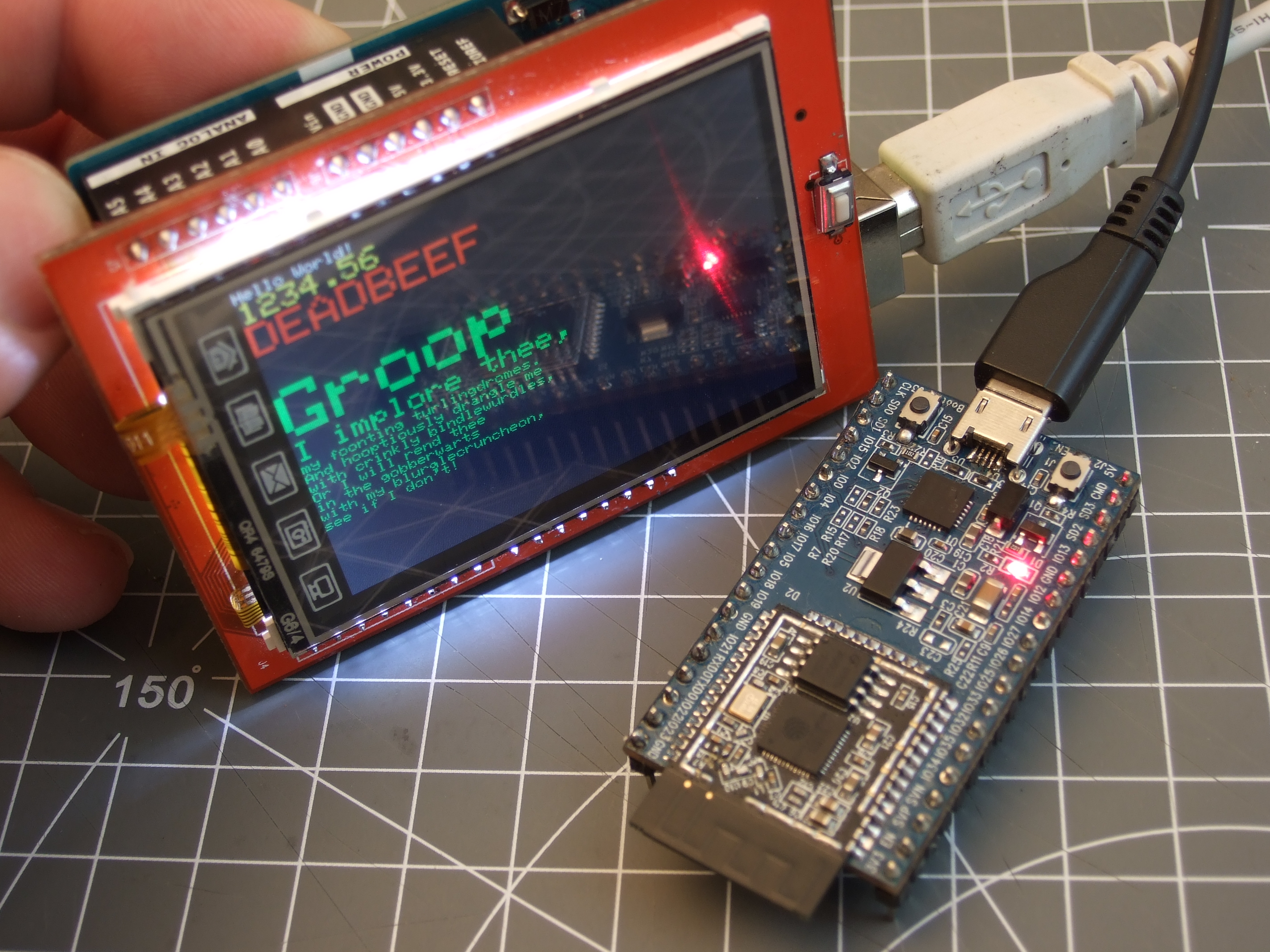
El Cheapo IL9341 TFT Display
Uno Lauging at ESP32
Since the SPI library works out of the box, the other various libraries that depend on it should as well, right? Well, kinda. I wasted an afternoon, and still failed. Why? I have a cheapo ILI9341 screen that only works with an old TFTLCD library, rather than with the nice Adafruit_ILI9341 libs. The former is so full of AVR-specific voodoo that it completely fails to compile, and is probably easier to re-write from scratch for the ESP32 than make work in its present form. The Adafruit library compiles fine, because it only depends on the SPI library, but it doesn’t work with my lousy screen.
Going repeatedly back and forth between these two libraries, my LCD experiment ended in tears and frustration: I couldn’t make either of them work. I scoped out the SPI data on a logic analyser, and it looked good, but it wasn’t drawing on the screen. At this point, a full line-by-line protocol analysis would have been needed, and that’s a few days worth of work. If I just wanted a running ILI9341 driver, I would go grab [Sprite_tm]’s NES emulator demo and use the one there, but it’s not Arduinified yet, so it’s out of bounds for the scope of this article.
DHT22 Humidity and Temperature Sensor
The Way It Should Work: Three Wires and Ten Lines of Code
Seeking a quick-and-dirty success, and beaten down by hours of hacking away for naught, I pulled a DHT22 sensor out of the eBay bin, and cloned Adafruit’s DHT library. Of course it didn’t compile straight out of the box, but there were only a couple of things that were wrong, and both turned out to be easily fixable.
ESP32’s Arduino didn’t have a microsecondsToClockCycles() function yet so I commented it out, multiplied by 240 MHz, and left a hard-coded constant in my code. This value was just used for a timeout anyway, so I wasn’t too worried. There are also some timing-critical code sections during which the Adafruit code uses an InterruptLock() function to globally enable and disable interrupts, but these functions weren’t yet implemented, so I just commented it all out and crossed my fingers.
After reassigning the data pin to one of the ESP32’s free ones (GPIO 27, FWIW), it compiled, uploaded, and ran just fine. I now know exactly how hot and humid it is up here in my office, but moreover have had a quick success with an Arduino external library, and my faith is restored.
Lessons from the Libraries
I suspect that these two examples are going to be representative of the ESP32-Arduino experience for a little while. Oddball hardware is going to take some time to get supported. Highly optimized libraries with cycle-correct timings or other microcontroller-architecture specific code in them will need to be ported over as well, despite being “Arduino” code. If you’re a code consumer, you’ll just have to wait while the wizards work their behind-the-scenes magic.
But there will also be a broad group of libraries that are written in a more-or-less device-independent way, and these should be easy enough to get working within fifteen minutes or so, as with the DHT sensor library. If you’re willing to compile, read the errors, and comment out or fix whatever shows up, some codebases will work in short order.
What’s Next? Turning Servos
Given that the Arduino-ESP32 port is brand new, indeed it’s still in progress, there is a lot of work for the community to do in getting it up to speed. Suppose that you need to drive a lot of servos, but the “Servo” library isn’t implemented yet. You’re an impatient coder. What to do? Get hacking!
The good news is that the Arduino-ESP32 libraries themselves are full of hints and examples for getting started. Open up the ESP32-specific directory that you cloned from GitHub. The usual *.cpp files provide the standard Arduino core functionality. The esp32-hal-xxx.h and esp32-hal-xxx.c files are chip-specific, and a tremendous help in taking advantage of the chip’s stranger options. For instance, esp32-hal-matrix.* gives you nice and easy access to the pin-routing matrix, which is a daunting task if you’re starting just from the datasheet.
Spot-On and Jitter-Free
But let’s get back to servos. The ESP32 chip has an intriguing hardware LED PWM peripheral that lets you assign up to sixteen channels to individual LEDS, specify the PWM frequency and bit-depth, and then control them by appropriately setting bits in hardware registers. If you think this would be hard to do by hand, you’d be right. The esp32-hal-ledc.* files provide helper functions to set up the hardware PWM generator, and with these libraries, getting a 16-bit LED fade in straight C or “Arduino” is easy. But our sights are set on servos.
To drive a hobby servo, one needs pulses between 1,000 and 2,000 microseconds each, repeated every twenty milliseconds or so. Setting the repetition rate to 50 Hz takes care of the first part, and each count is 20 ms / 65,635 ticks long, or roughly 0.3 microseconds. Setting the PWM width value to something between 3,300 and 6,500 generates pulses in the right ballpark, and my servo ran jitter-free (and a clean signal was confirmed on the oscilloscope). Here’s all it took:
That wasn’t so hard, was it? It’s not “Arduino”-style — there’s no objects or classes or methods anywhere in sight — but thanks to a straightforward and well-written hardware abstraction layer, using the very complicated peripherals is made pretty simple. Kudos to [me-no-dev] for his work on the back-end here. The HAL inside the Arduino libraries is currently the best source of code examples on many of the chip’s more esoteric and interesting peripherals.
Conclusion?
The short version of my dive into Arduino-esp32 is that there’s a lot here, even though it’s not done yet. Blinking LEDs and other simple GPIO is a given, and the core communication libraries that are already implemented worked for me: GPIO, WiFi, SPI, and I2C are up and running.
Non-core libraries are hit and miss. I suspect that a lot of them will work with just a little bit of tweaking. Others, especially those that are architecture-dependent, may not be worth the effort to port and will need to be re-written. The ESP32 has a bunch of interesting and innovative hardware peripherals onboard and there’s certainly no Arduino libraries written for them yet, but there’s some great HAL code hidden away in the Arduino-ESP32 codebase that’ll give you a head start. We could get lost in there for hours. Time to get hacking!
The ESP32 is still a new chip, but orders should be coming in soon. Have one? Want to see us put other libraries or languages through their paces? Let us know in the comments.


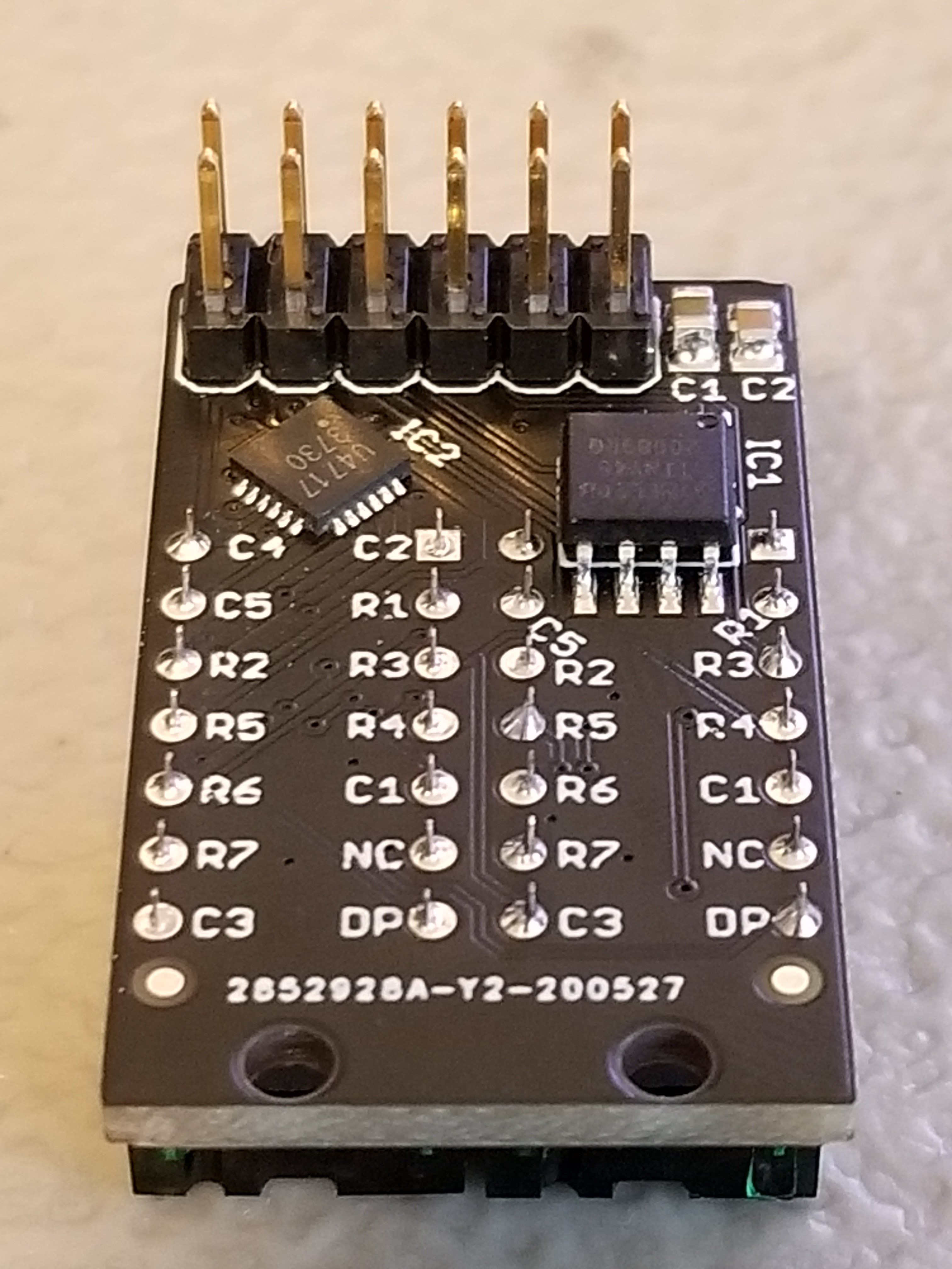 Each Pixie module is designed to host two gorgeous little