Posts with «bluetooth» label

Sound Camera.


One more project, that shows breathtaking beauty of the FFT (Fast Fourier Transform). Once again, like in last 3D Ultrasonic Radar Project,    Arduino DUE was nominated to be Maestro, doing major part of the Digital Signal Processing in real time.  As you can see below, the hardware includes 4 “modules”:

  1. Sensor board
  2. Arduino DUE
  3. Bluetooth shield
  4. Android tablet.

Last two items aren’t strictly necessary. Alternative would be to connect TFT display directly to arduino, but I decided not to spend my time on re-inventing drawing-rendering software. Better to delegate all visualization stuff to the equipment that was  specifically design by big monsters in high tech industry.  I spend quite time digging into android graphics subject anyway, only hoping I can apply my knowledge somewhere else later on.

Sensor board holds 4 microphones from  SFE.  Plus a few decoupling components, capacitors and inductor in power line.

Software.

   Brief summary: Arduino sampling 4 analog inputs, close to 41 kHz,  x 4 = 164 ksps,  software library Radix4 posted on this blog was imported into project practically intact. DMA feature on Arduino DUE allows sampling rate up to 1 MSPS, and I already successfully tested its capability in 3D Radar project.  Having 2048 fft size, at the first processing stage  output there are 1024 bins 20 Hz each. Than, using arctangent LUT, phase of each bin is extracted.  Difference in phases two vertically position microphones gives Y component, and two horizontally spaced mic’s – X component. Sound source is localized with accuracy ~ 0.5 degree. Have to say, that on the lower frequency end, 100 Hz – 1 kHz , where wavelength is huge compare to spacing between two mic’s ( 3.4 meters at 100 Hz ), accuracy is deteriorating proportionally to wavelength.

Arduino is calculating data really fast, providing  X,  Y, and M  every 50 milliseconds. M – is for magnitude. Than, all this data stream flows to android over BT.  Everything else is obvious, watch the video.

Speaker outputs white noise, as for single tone (frequency) only one pixel would be visible on screen. Android software “colorized” picture based on a frequency, low range – starting from red, and up to violet on high end of the frequency band, through all 1024 color wheel possibilities.  You can see, that picture saturated with green and blue, and there is almost no red color. There are two things, first is a speaker, not performing well at low end. Second nuance is the fact, that low frequencies are not “grouped” so effectively, due to the localization error, what I tried to explain in a paragraph above. I created an option in the menu to select different types of colorization, based on a frequency or based on a magnitude. They are look pretty similar for white noise source, so there is only one video clip.

Have fun.


 Edited on 21 Oct. 2014:

 If you come across this page searching an old  “Localizator” project, published over 2 years ago, here is working material I was able to find:   Localizator.


Sound Camera.


One more project, that shows breathtaking beauty of the FFT (Fast Fourier Transform). Once again, like in last 3D Ultrasonic Radar Project,    Arduino DUE was nominated to be Maestro, doing major part of the Digital Signal Processing in real time.  As you can see below, the hardware includes 4 “modules”:

  1. Sensor board
  2. Arduino DUE
  3. Bluetooth shield
  4. Android tablet.

Last two items aren’t strictly necessary. Alternative would be to connect TFT display directly to arduino, but I decided not to spend my time on re-inventing drawing-rendering software. Better to delegate all visualization stuff to the equipment that was  specifically design by big monsters in high tech industry.  I spend quite time digging into android graphics subject anyway, only hoping I can apply my knowledge somewhere else later on.

Sensor board holds 4 microphones from  SFE.  Plus a few decoupling components, capacitors and inductor in power line.

Software.

   Brief summary: Arduino sampling 4 analog inputs, close to 41 kHz,  x 4 = 164 ksps,  software library Radix4 posted on this blog was imported into project practically intact. DMA feature on Arduino DUE allows sampling rate up to 1 MSPS, and I already successfully tested its capability in 3D Radar project.  Having 2048 fft size, at the first processing stage  output there are 1024 bins 20 Hz each. Than, using arctangent LUT, phase of each bin is extracted.  Difference in phases two vertically position microphones gives Y component, and two horizontally spaced mic’s – X component. Sound source is localized with accuracy ~ 0.5 degree. Have to say, that on the lower frequency end, 100 Hz – 1 kHz , where wavelength is huge compare to spacing between two mic’s ( 3.4 meters at 100 Hz ), accuracy is deteriorating proportionally to wavelength.

Arduino is calculating data really fast, providing  X,  Y, and M  every 50 milliseconds. M – is for magnitude. Than, all this data stream flows to android over BT.  Everything else is obvious, watch the video.

Speaker outputs white noise, as for single tone (frequency) only one pixel would be visible on screen. Android software “colorized” picture based on a frequency, low range – starting from red, and up to violet on high end of the frequency band, through all 1024 color wheel possibilities.  You can see, that picture saturated with green and blue, and there is almost no red color. There are two things, first is a speaker, not performing well at low end. Second nuance is the fact, that low frequencies are not “grouped” so effectively, due to the localization error, what I tried to explain in a paragraph above. I created an option in the menu to select different types of colorization, based on a frequency or based on a magnitude. They are look pretty similar for white noise source, so there is only one video clip.

Have fun.


Arduino-based LED Wedding Lights

[Rob] created these amazing Bluetooth controlled LED lights for his daughter’s wedding adding a colorful ambient glow to the ceremony. Each item held a Neopixel ring and an Arduino microprocessor with a wireless module that could be individually addressed over a ‘mini-network.’ The main master station would receive commands from a Windows Phone. Usually we see Arduino-based projects being run with Android apps, so it’s nice to see that Microsoft is still present in the maker community.

The enclosures and translucent vases that sit atop the devices were 3D printed. All eight of the matrimonial units synchronized with each other, and the colors could be changed by sliding the settings bar on the app.  [Rob] says that it was a lot of fun to build, and jokingly stated that it kept him “out of all the less important aspects of the ceremony. (food choice, decor, venue, who to marry etc etc).” The outcome was a beautiful arrangement of tabletop lighting for the wedding. A demo of [Rob]‘s setup can be seen in the video below.


Filed under: led hacks

Ultrasonic 3D Radar.

This page is next level of Virtual Touch Screen project. 

Do you have this impression, like video I posted earlier was outdated? Software to draw a handwriting, mouse interface, etc. Wouldn’t it be nice to use a new era  technology? And here it is.

Technically, there are two hardware parts were added, to fully demonstrate extra ordinary sensitivity of the VTS project. First one is the BlueTooth module. And second is a tablet, running android. Device that I have, doesn’t support USB host mode (OTG), otherwise I may be fine w/o BT, just transfer a data over USB cable, as it was done in two previous demo video clips.  Have to say, it was not easy to represent 3D perspective on a flat screen, and picture below shows what I designed to complete a task:

Don’t think it requires a comments, the tricky part was to create an elliptical grid to show a distance. The number of circles is not limited to 2, I’d think about how to film next demo video, that ‘d show a “volume”.

Enjoy the movie:


Ultrasonic 3D Radar.

This page is next level of Virtual Touch Screen project. 

First things is a distance, for virtual touch screen its less than 3 m, because the reflective area is too small. For radar (or sonar) its different, and the bigger size of object the stronger echo. Approximated range of detection the object as big as a wall, 30 meters.

Technically, there are two hardware parts were added, to fully demonstrate extra ordinary sensitivity of the VTS project. First one is the BlueTooth module. And second is a tablet, running android. Device that I have, doesn’t support USB host mode (OTG), otherwise I may be fine w/o BT, just transfer a data over USB cable, as it was done in two previous demo video clips.  Have to say, it was not easy to represent 3D perspective on a flat screen, and picture below shows what I designed to complete a task:

Don’t think it requires a comments, the tricky part was to create an elliptical grid to show a distance. The number of circles is not limited to 2, I’d think about how to film next demo video, that ‘d show a “volume”.

Enjoy the movie:

There are two apples, and arduino measure position in 3D space both of them. X, Y, and Z coordinates plus P – power of reflected ultrasonic wave used to draw circles, with different colors. You can see movement of the red circle on screen when first apples moves.

edited on 21-08-2014

After thinking awhile how to show a “volume” on a flat tablet screen, I decide to remove filtering stage in a software, when a bunch of consecutive “layers” were shown as one single ring (object) on a screen. Now each packet of data received from single “spherical” layer creates a circle. As always packet includes X, Y, Z, and P. To make an image “clear” there are two others filters left over in the processing algorithm. One is rejecting data below ( selectable in a menu ) power threshold, and another rejects anything thats located farther specific (again, selectable) distance. This is why in a video you can see only a ball, but not me – operator making a movie.

Here is how the ball looks like on radar screen:

And video:

That;s it for now.


The world knows what you did last summer


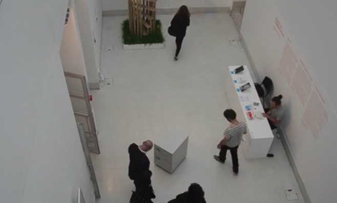
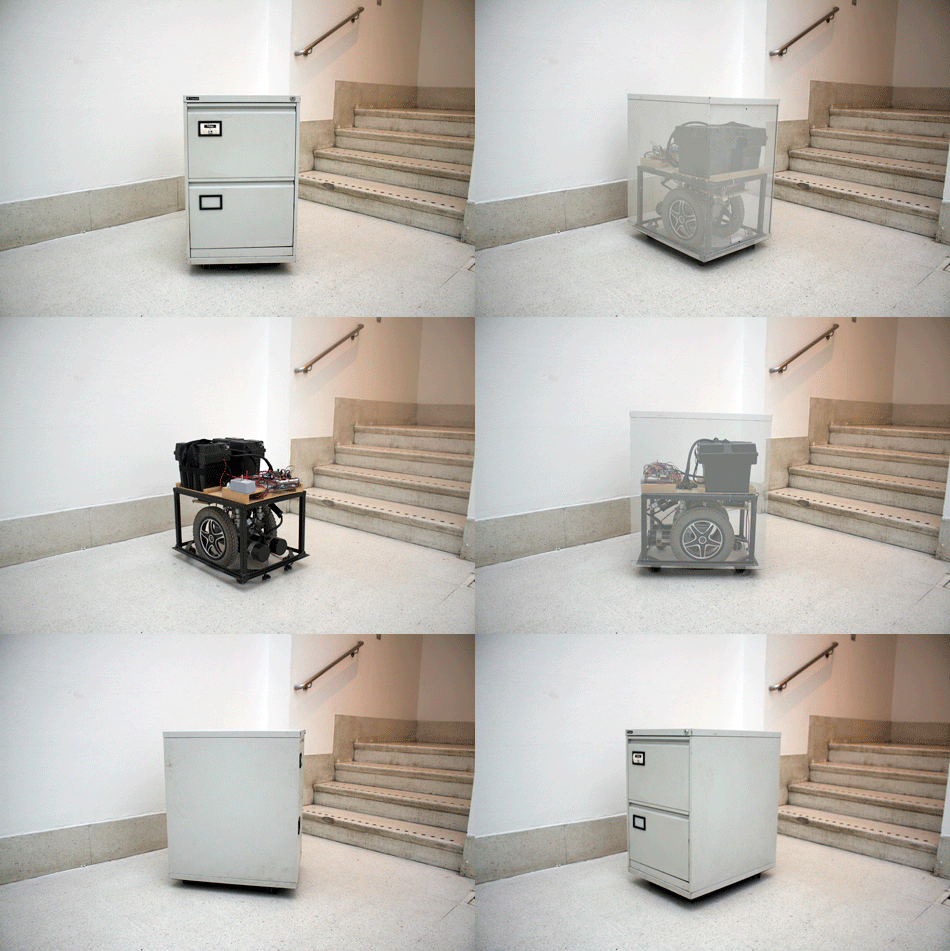
Jaap de Maat shared with us his final year project called I know what you did last summer, the finale to a two-year-long MA in Information Experience Design of the Royal College of Art. The ingredients are  simple (an old electric wheel chair, an Arduino Mega, 12v motor board, Bluetooth slave, wires, blood sweat and tears) and the concept is very actual:

It is physically impossible for the human brain to remember every event from our past in full detail. The default setting is to forget and our memories are constructed based on our current values. In the digital age it has become easier to look back with great accuracy. But this development contains hidden dangers, as those stored recollections can easily be misinterpreted and manipulated. That sobering thought should rule our online behaviour, because the traces we leave behind now will follow us around for ever.

The video of the installation shows how the physical presence of an archive drawer  stalking has a real impact on visitors:

Here’s the making of the prototype:

Arduino Blog 08 Jul 20:53

Hands on with the Light Blue Bean

We took an initial look at Punch Through Design's Light Blue Bean when they opened for pre-orders. Now we have our hands on the hardware it's time to take a closer look.

Read more on MAKE

The Bluetooth LE doc-a-thon at ITP Camp

Getting started using Bluetooth LE is much harder than it should be, and that a lot of great work people are doing is getting dropped on the floor, or worse yet done again. We decided to sit down and do something about that.

Read more on MAKE

Make it Great: Bluetooth Multimedia Remote

I recently put an old laptop in my room as an XBMC computer. However, whenever I wanted to switch the content that was playing, I would have to drag myself out of my warm bed to change the content on the computer. I searched far and wide for a glitch […]

Read more on MAKE

A Tweeting Litter Box

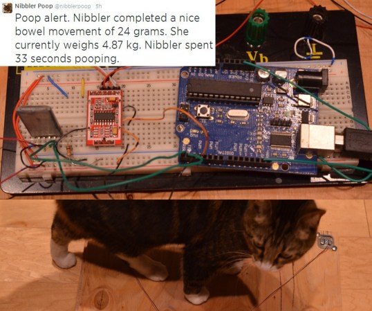
How can you not be interested in a project that uses load cells, Bluetooth, a Raspberry Pi, and Twitter. Even for those of our readers without a cat, [Scott's] tweeting litter box is worth the read.

Each aspect of this project can be re-purposed for almost any application. The inexpensive load cells, which available from eBay and other retailers, is used to sense when a cat is inside the litter box. Typically sensors like the load cell (that contain a strain gauge) this use a Wheatstone bridge, which is very important for maximizing the sensitivity of resistive sensor. The output then goes to a HX711, which is an ADC specifically built for load cells. A simple alternative would be using an instrumentation amplifier and the built-in ADC of the Arduino. Now, the magic happens. The weight reading is transmitted via an HC-06 Bluetooth module to a Raspberry Pi. Using a simple Perl script, the excreted weight, duration, and the cat’s resulting body weight is then tweeted!

Very nice work! This is a well thought out project that we could see being expanded to recognize the difference between multiple cats (or any other animal that goes inside).


Filed under: Arduino Hacks, Raspberry Pi, wireless hacks