Posts with «bluetooth» label

NES controllers for any Bluetooth application

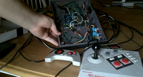
[Dustin Evans] wanted to used his original NES controllers to play emulated games. The problem is he didn’t want to alter the classic hardware. His solution was to use the connectors and enclosure from a dead NES to build a Bluetooth translator that works with any NES controller.

Here he’s showing the gutted half of an original NES. Although the motherboard is missing, the connectors for the controllers are still there. They’ve been rewired to an Arduino board which has a BlueSMiRF modem. The controller commands are harvested by the Arduino and sent to whatever is listening on the other end of the Bluetooth connection. He also has plans to add a couple of SNES ports to the enclosure so that those unaltered controllers may also be used.

In the video after the break [Dustin] walks us through the hardware setup. He then demonstrates pairing the device with an Android phone and playing some emulators with the pictured controllers.


Filed under: nintendo hacks, peripherals hacks

How to make a controlled Arduino Robot via Bluetooth by using an Android Device

Can you Please teach me How to make a controlled Arduino Robot via Bluetooth by using an Android Device :D 


I found some Application in Play Store about the Bluetooth controller, it is called Bluebots ,a Bluetooth remote control for robot. (see below)

https://play.google.com/store/apps/details?id=blue.bots.free.matt&feature=search_result#?t=W251bGwsMSwxLDEsImJsdWUuYm90cy5mcmVlLm1hdHQiXQ..

read more

Let's Make Robots 25 May 11:40

The age of the invisible steering wheel

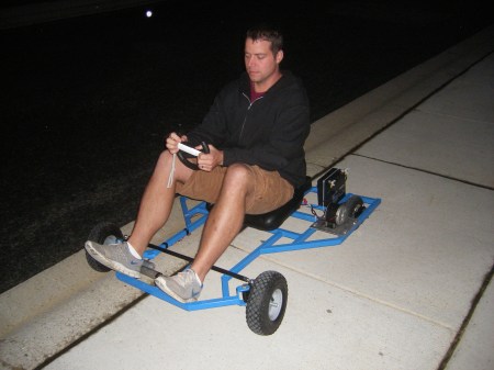
A Nintendo Wii-remote along with bluetooth communication and an arduino gives us this magical cart with a wireless steering wheel.

These cool people are staunch DIY-ers and would love to see the community build more such vehicles.

The cart has two motors which use a chain to drive each of the rear wheels. A pair of H-bridge controllers let the Arduino interface with them. It’s also has a Bluetooth module that makes it a snap to pull accelerometer data from the Wii remote. The front end looks like it uses rack and pinion steering, but you won’t find a pinion or a steering column. Instead, a linear actuator is mounted parallel to the rack, moving it back and forth at the command of the Arduino.

The only downside I spot is the Battery life. I am sure that would be worked out too! Till then – Kudos to the inventors! I smell futuristic looking vehicle controls here.

Via:[Hackaday, NewsFactor]

Arduino Blog 13 May 22:12

NFR24L01 bluetooth module and SPI

Hi


I am working on my first robot. Ibased it on an ArduinoMega128 and can make it drive a pre-programmed pattern. I now want to control it via bluetooth from my android phone. For this I was given a small BT module yesterday. It is based on the NFR24L01 chip, and contains no serial interface, but rather the default SPI that the chip communicates with. I know the Arduino has an SPI interface on leg 50-53. However, away from connecting, I have no idea on how to begin.


I know I need to add the #include spi.h to my Arduino sketch.

read more

Bluetooth communications between Arduino and Android: an introduction

John Boxall of Tronixstuff has written a very interesting tutorial article on his blog about how to connect any Android-based smartphone with an Arduino board, by means of Seeedstudio’s Bluetooth Bee and a promising, yet simple – open-source Android application, named BlueTerm, which provides RFCOMM/SPP serial communication capabilities.

In this introductory video, John shows how to wirelessly turn on and off Arduino’s digital pin with his setup.

Read more on Tronixstuff.

Via:[Seeedstudio Blog]

Arduino Blog 07 May 08:26
bluetooth  bt  wireless  

Wise Clock 4 with remote "Alarm stop" button

The Ramos project brought the novel idea of a wireless alarm-stop button: instead of just reaching out to the press on the top of your nightstand alarm clock, you now have to actually get out of the bed and walk to a remote corner of your dwelling to click on a keypad. No chance you will return to sleep afterward :)

This remote alarm-stop feature for Wise Clock 4 can be implemented in several different ways, all of them using of the on-board XBee socket:
  • through a Bluetooth module;
  • through WiFi, using the Roving Networks WiFly module;
  • through XBee radios.
The cheapest and easiest would be the Bluetooth solution, providing that you already have a BT device (e.g. Android phone/tablet) to communicate with. In pseudo-code, it should look like this:

if (alarm is ON)
{
    while (Serial1.available())
    {
       read characters received;
       if (it is the expected string)
       {
            set alarm OFF;
        }
    }
}

The WiFi solution would require a second WiFi device (phone/tablet) to access a web site, or maybe they could talk directly (sockets), using their IP addresses.

The solution based on XBee relies on direct communication between two XBee radios. One would have to build the remote device, probably around an Arduino, with a keypad and an XBee.


Scrolling message sign with Bluetooth

A simple application for Bluetooth was suggested a while back by fellow arduinoer evanrich (who also created a home for his project on github): a scrolling sign using several cascaded 3216 displays and controlled through Bluetooth from an Android phone. His intention was to use it as a wireless sign that can be put in the back of the car to tell drivers to get off his tail.

I gave it a try myself, using Wise Clock 4 with Bluetooth and two 3216 displays, as shown in this photo (the blue LED on the BTBee is power, the orange one is communication status).


The code is a modified version of the one posted here.

This message sign, especially if it is made with the larger (5mm) 3216 displays, can be also used in waiting rooms, call centers, stores etc, to show dynamic and easily-changeable messages.


Related posts:


Wise Clock 4 with Bluetooth

Another thing that was supposed to be easy, but it wasn't: Arduino communicating with Windows XP through Bluetooth.

Like everybody, I purchased the cheap and ubiquitous Bluetooth module from dealextreme.
I soldered it myself on the XBee-footprinted PCB (bare BTBee from IteadStudio), for a total price of about $8 (compare that to at least $15 as these Bluetooth XBees go for).

Without knowing much about Bluetooth, I plugged this new "BTBee" module in Wise Clock 4 expecting it to be "discovered" by XP (which has an USB Bluetooth dongle). Discovered it was: the name "linvor" appeared in the list of BT devices, with two serial ports attached to it.

Communication between XP and BT module is performed through the serial ports, I figured. Tried CoolTermWin, HyperTerminal, Putty, on both ports, nothing seemed to work. Time to read the documentation (which always reminds me of that joke). I learned that others had similar problems, and some have solved them by installing new BT drivers. The best advice came from this post. Putty did not work for me, so I stuck with what I had, namely HyperTerminal.

So here is my own step-by-step tutorial on how to make an Arduino communicate with Windows XP via a Bluetooth module.
Note: From the Bluetooth perspective, Wise Clock 4 I used for my testing is similar to Arduino.

1. Upload this simple sketch that "echos" what it reads from Bluetooth and also broadcasts a message periodically. The communication between Arduino and the BT module is serial, with a baud rate of 9600, according to the documentation.

#if ARDUINO < 100
  #include
#else
  #include
#endif


void setup()
{
  Serial.begin(9600);
}


void loop()
{
  while (Serial.available())
  {
    // get char from bluetooth;
    char inChar = (char) Serial.read();
    // output it back, between brackets;
    Serial.print('[');
    Serial.print(inChar);
    Serial.print(']');
  }
  // broadcast message;
  Serial.print("millis() from Arduino: ");
  Serial.println(millis());
  delay(2000);
}

2. Power Arduino, with the BT module connected, and let it run the sketch.

3. Make the BT module (on the Arduino) visible to XP, by adding it to the list of Bluetooth devices. For this, click on the "Bluetooth Devices" icon in the tray (bottom right corner of the XP's desktop). You will see this box.


Next, you will see the BT device added to the list, under the name "linvor".


Then select the last option, "Don't use a passkey". Although it makes little sense at this point (since you know that the passkey is 1234, according to the documentation), it is very important to not use a passkey here.


The last step of the wizard shows the two ports that have been added. Write down the "Outgoing COM port", since this is the one we will be using for communication (step 4).


4. Open HyperTerminal to establish the 2-way communication between XP and Arduino, via Bluetooth.
Select, from the list, the COM port specified as "outgoing" for the BT device.


Next, you will be shown this pop-up.


After you click on it, you are prompted to enter the passkey, the one you (reluctantly) skipped in the process of setting up the BT device. Type "1234", as specified in the BT module documentation.


After hitting "Next", you are shown this last confirmation box.


In the same time, the HyperTerminal starts displaying the message coming from Arduino.


Note that, when the COM port was opened in Auto mode, no parameters (baud rate etc) being specified.
Interestingly, after the communication is established, the baud rate is reported as 2400 for some unexplained reason.
You can also type characters in HyperTerminal and they will be echoed back, between brackets, by Arduino.

Optionally, if you want to see what you typed (before the echoing from Arduino takes place), you can enable local echo, by selecting "Properties", then "ASCII Setup".


Once the communication between XP (HyperTerminal) and Arduino is established via Bluetooth, the "Status" LED (if you have it soldered) is on continuously. When the BT module is not communicating, the "Status" LED is blinking at a frequency of about 2Hz.

The next time a HyperTerminal session is opened, XP remembers the BT device and the communication params (ports, passkey) and does not ask to set it up again. (I guess that's why it is called "pairing", although this word does not appear anywhere in the process.)


Time to write some serious applications using Bluetooth:)