Modified Uke Keeps the Beat with a Solenoid
A classic one-man band generally features a stringed instrument or two, a harmonica in a hands-free holder, and some kind of percussion, usually a bass drum worn like a backpack and maybe some cymbals between the knees. The musician might also knock or tap the sound-boards of stringed instruments percussively with their strumming hand, which is something classical and flamenco guitarists can pull off with surprising range.
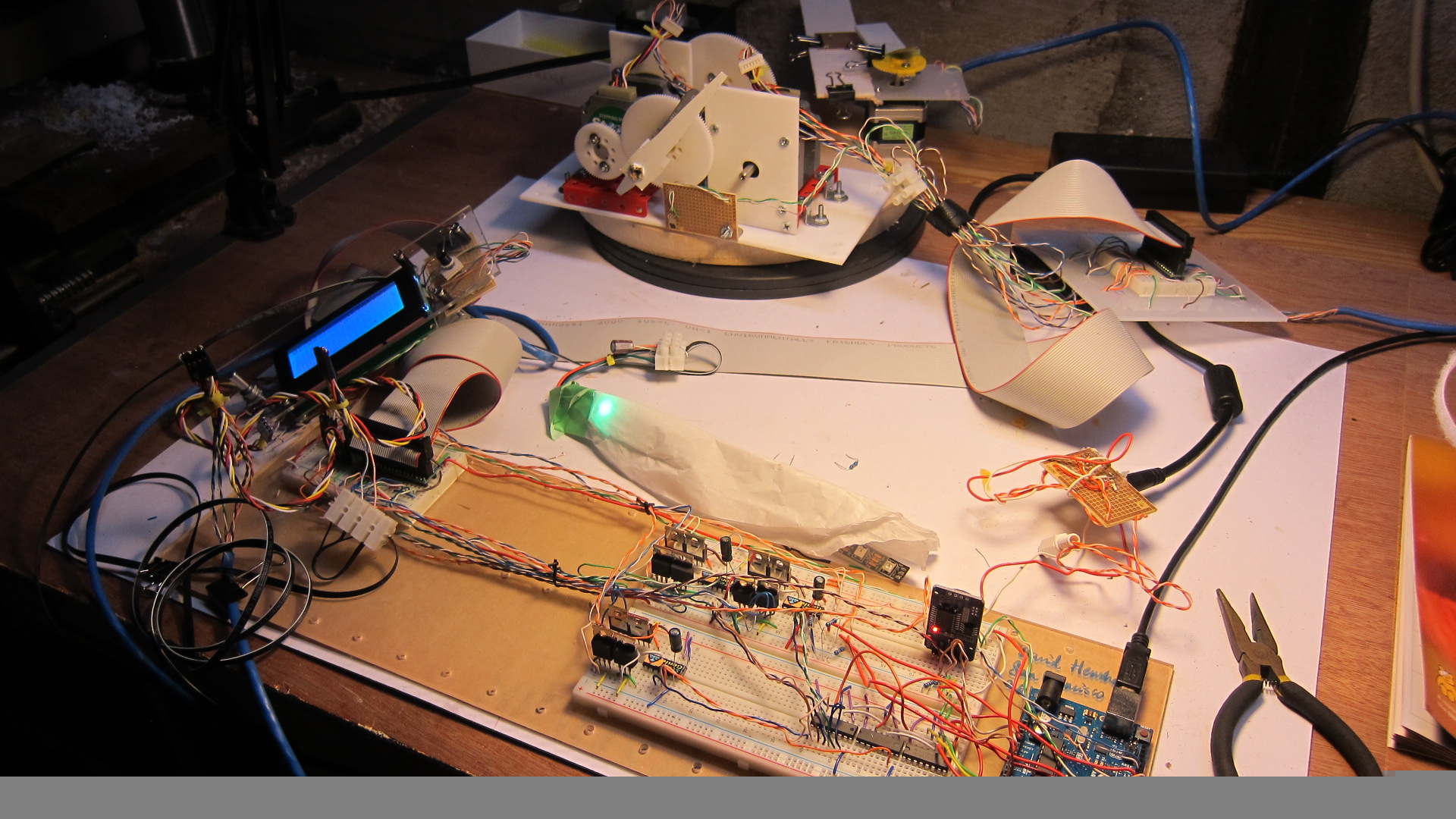
The musician usually has to manipulate each instrument manually. When it comes to percussion, [JimRD] has another idea: keep the beat by pounding the soundboard with a solenoid. He built a simple Arduino-driven MOSFET circuit to deliver knocks of variable BPM to the sound-board of a ukulele. A 10kΩ pot controls the meter and beat frequency, and the sound is picked up by a mic on the bridge. So far, it does 3/4 and 4/4 time, but [JimRD] has made the code freely available for expansion. Somebody make it do 5/4, because we’d love to hear [JimRD] play “Take Five“.
He didn’t do this to his good uke, mind you—it’s an old beater that he didn’t mind drilling and gluing. We were a bit skeptical at first, but the resonance sweetens the electromechanical knock of the solenoid slug. That, and [JimRD] has some pretty good chops. Ax your way past the break to give it a listen.
Got a cheap ukulele but don’t know how to play it? If you make flames shoot out from the headstock, that won’t matter as much. No ukes? Just print one.
Filed under: Arduino Hacks, Musical Hacks