Posts with «arduino mega» label

Add smartphone control to your rolling backpack

Have you ever hopped off the plane at LAX with a… rolling backpack, and wished it would just push itself? Using an Arduino and motor controllers, “TannerTech” made his own robo-backpack.

Carrying backpacks around is so 20th century. Modern travelers, of course, get their robotic minions to drive the bags around for them. Or at least that’s what this Maker’s vision seems to be. The backpack in question is wheeled around by two motors on mounts made out of paint sticks. Control is provided by an Arduino Mega using an H-bridge motor controller to handle the relatively high current required.

In order for a human to call the backpack to him or herself, an “Arduino bluetooth controller” Android app is used to send characters to the Mega and Bluetooth module in the bag. Electronics are housed inside of a pencil case, making this a surprisingly accessible project.

You can find out more on TannerTech’s Instructables page, and see a demo of it below!

Particle Flow makes granules tumble in interesting patterns

This Arduino-based project creates interesting tumbling patterns using a system that tilts a plane in a controlled manner while deforming its surface.

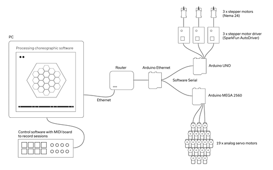
NEOANALOG, a “studio for hybrid things and spaces,” was commissioned to build the Particle Flow installation, which explores how granules tumble under the control of gravity. This mechanism takes the form of a large hexagon held in three corners by linkages pushed up and down by NEMA 24 stepper motors. As these rods are lifted, the granules inside the “arena” are steered over to the opposite side producing a zen-like experience.

Inside the main hexagon are 19 smaller hexagons, each controlled by servos to lift an individual section of the rolling surface up and down. Control of the entire system is accomplished via a PC running Processing, which sends commands via Ethernet to an Arduino Mega and the steppers to an Arduino Uno with three motor drivers. 

A moving slanted plane and a grid of motorized stamps control the elements to form infinite variations of behaviors and patterns. The result is a zen-like experience that is both: fascinating and contemplative. Software controlled motion follows a complex choreography and enables precise steering of physical particles in a variety of ways: from subtle to obvious, from slow to high paced, from random-like to symmetric.

Intrigued? Be sure to check out Creative Applications Network’s write-up on this piece as well as NEOANALOG’s page for more details.

An interactive LED floor to get the dance party started

If you want a light-up dance floor for your next wedding or other special event, you can rent one; however, that can be quite expensive. On the other hand, you and your hacker friends can always build one. How hard can that be?

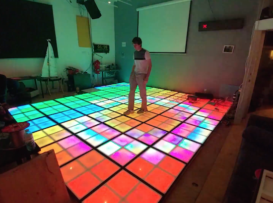
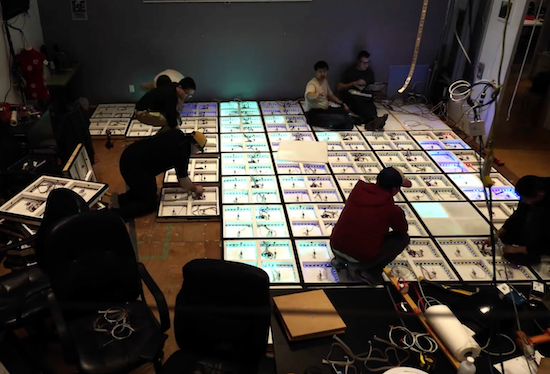
Turns out, very hard. While it may be simple to get one translucent panel to illuminate with LEDs, this 17-square-foot interactive dance floor used 64 panels with four lighting cells in each, for a total of 256 lighting arrays and 7,680 RGBs arranged as 2,560 addressable pixels.

Even with some advanced tools like a pick-and-place machine for PCB manufacturing, as well as a laser cutter, it still took volunteers many hours over the course of 11 months to get it working. LED control is accomplished via a Teensy 3.1, while 256 pressure switches under the surface are read by an Arduino Mega.

You can see more details of the impressive project in the video below (including a round of multi-player Dance Dance Revolution) and a few more technical details in AvBrand’s write-up here.

Build a motorized gimbal on a budget with Arduino

Tadej Strah, a freshman at Gimnazija Vic in Slovenia, made a motorized gimbal using only $60 worth of parts.

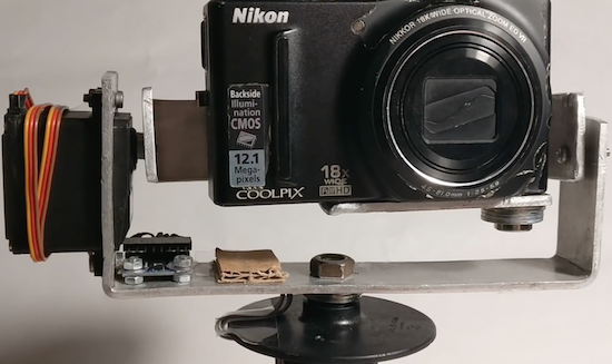
After joining a photo and film club at his university, Strah was inspired by a member with cerebral palsy to build an inexpensive gimbal to keep a small camera level. His project uses an MPU-6050 sensor to detect motion, and an Arduino Mega to process this data and control the device’s two servos. The setup includes a handle from an angle grinder, while the servos are mounted on bent pieces of metal, helping keep the cost down.

Strah believes that with a few upgrades, such as a smaller battery, Bluetooth connectivity, and a 3D-printed frame, it should be able to provide many of the features of those available for $500 or more. Hopefully we’ll see this design become even better in the future!

Until then, you can follow along with Strah’s progress, and perhaps another iteration of his gimbal, on his YouTube channel.


Well Engineered Radio Clock Aces Form and Function

Clocks that read time via received radio signals have several advantages over their Internet-connected, NTP-synchronised brethren. The radio signal is ubiquitous and available over a fairly large footprint extending to thousands of kilometres from the transmitting antennae. This allows such clocks to work reliably in areas where there is no Internet service. And compared to GPS clocks, their front-end electronics and antenna requirements are much simpler. [Erik de Ruiter]’s DCF77 Analyzer/Clock is synchronised to the German DCF77 radio signal, which is derived from the atomic clocks at PTB headquarters. It features a ton of bells and whistles, while still being simple to build. It’s a slick piece of German hacker engineering that leaves us amazed.

Among the clock functions, it shows time, day of the week, date, CET/CEST modes, leap year indications and week numbers. The last is not part of the DCF77 protocol but is calculated via software. The DCF77 analyzer part has all of the useful information gleaned from the radio signals. There are displays for time period, pulse width, a bit counter, bit value indicator (0/1) and an error counter. There are two rings of 59 LEDs each that provide additional information about the DCF77 signal. A PIR sensor on the front panel helps put the clock in power save mode. Finally, there is a whole bunch of indicator LEDs and a bank of switches to control the various functions. On the rear panel, there are RJ45 sockets for the DCF77 receiver antenna board, temperature sensor and FTDI serial, a bunch of audio sound board controls, reset switches and a mode control switch.

His build starts with the design and layout of the enclosure. The front panel layout had to go through a couple of iterations before he was satisfied with the result. The final version was made from aluminium-coated sandwich-panel. He used an online service to photo-etch the markings, and then a milling machine to carve out the various windows and mounting holes. The rear panel is a tinted acrylic with laser engraving, which makes the neatly laid out innards visible for viewers to appreciate. The wooden frame is made from 40-year-old Mahogany, sourced from an old family heirloom desk. All of this hard work results in a really professional looking product.

The electronics are mostly off the shelf modules, except for the custom built LED driver boards. The heart of the device is an Arduino Mega because of the large number of outputs it provides. There are seven LED driver boards based around the Maxim 7221 (PDF) serial interface LED drivers – two to drive the inner and outer ring LEDs, and the others for the various seven-segment displays. The numerous annunciator LEDs are driven directly from the Arduino Mega. His build really comes together by incorporating a noise resilient DCF77 decoder library by [Udo Klein] which is running on a separate Arduino Uno. All of his design source files are posted on his GitHub repository and he hopes to publish an Instructable soon for those who would like to build one of their own.

In the first video below, he walks through the various functions of the clock, and in the second one, gives us a peek in to its inside. Watch, and be amazed.

Thanks for the tip, [Nick]


Filed under: clock hacks

Selectively silence a landline phone with Arduino

Silencing a smartphone at night isn’t difficult, but if you have a landline, Arduino can help!

Before computer hacking/modding became accessible, the next best thing was to creatively explore the phone system via custom electronics. Though this pursuit, known as “phone phreaking,” has largely gone away, some people still have landlines. As “MolecularD” shows in this Instructables writeup, with a few components you can creatively trick your phone into not ringing on your end, while appearing to the caller to simply ring and ring as if no one is home.

In order to make it much more useful, MolecularD hooked up an Arduino Mega with a real-time clock module to turn the device on and off depending on the time of day. Now calls from phone solicitors, or “IRS agents” at 4 in the morning can be eliminated automatically. As noted, this may or may not be legal where you live, so attempt it at your own risk!

Need desk lighting? How about 1,200+ LEDs?

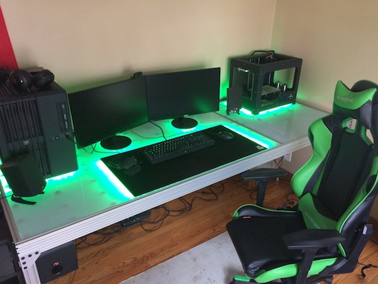
After he’d just finished a project using RGB LEDs, Imgur user nolobot’s brother mentioned he needed a new computer desk. Most people would probably just let their brother buy one, others would make something out of wood, but nolobot instead decided to create something truly amazing using more than 1,200 WS2812 RGB LED modules, an Arduino Mega, aluminum extrusion, and translucent polycarbonate.

The Mega controls these LEDs with the FastLED library, which are sandwiched between a base piece of plywood and a strip of polycarbonate using custom spacers. This diffuses the light nicely, allowing for beautiful light animations directly on the desk’s surface.

You can find more on this awesome build on the project’s Imgur page!

Giant interactive crossword puzzle uses over 130 Arduino

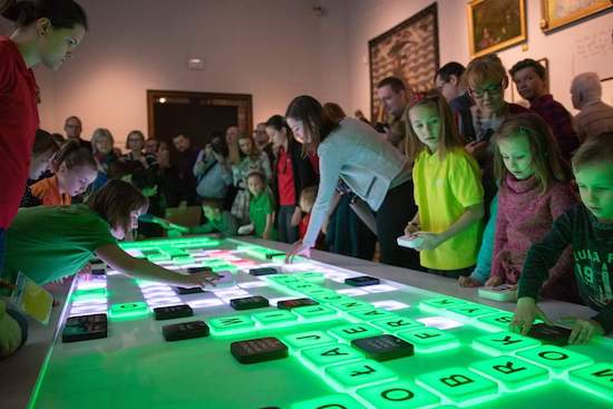
In what is perhaps the most Arduino boards used together, 130 Arduino Nanos, (plus an Arduino Mega), 130 RFID readers, and 750 RGB LEDs power this interactive crossword puzzle.

As you might suspect, bringing a giant crossword puzzle to life was lot of work. If you’d like to know how much, you can see the process laid out in the video below. Like many great hacks, this project starts out with a lot of prep, making sure the mechanical pieces go together as they should. Everything is then wired and programmed, and on day six, it finally goes out the door, destined for the National Museum in Warsaw, Poland.

Each letter has an RFID tag. Under the table are custom made circuits with Arduino Nano, RFID reader, and WS2812B. There is 130 of those circuits and the are connected by I2C interface together to Arduino Mega 2560, which is the main brain. So basically, the table recognizes letters and takes proper actions.

  • When there is no letter: LED are dimmed white
  • When letter is good: LED are green
  • When letter is bad: LED are red
  • When whole word is completed: LED play colorful animation
The main controller (Arduino Mega) communicates with a PC via RS-232. This PC plays special graphic visualization on the wall. When the whole crossword is completed, the whole table begins doing disco + sound effects.

It’s quite a colorful display, and it looks like the kids playing with it in the “Anything Goes” exhibition love it! You can see more about this project in Robert Mordzon’s write-up.

Huge Interactive Crossword

Give kids some responsible and challenging tasks, and you’d be surprised at the results. The “Anything Goes” exhibit at the National Museum in Warsaw was aimed as a museological and educational experiment. A group of 69 children aged 6–14 was divided into teams responsible for preparing the main temporary exhibition at the museum. Over six months, they worked on preparing the exhibition during weekly four-hour meetings. They prepared scripts, provided ideas for multimedia presentations, and curated almost 300 works for display. One of those was [Robert Mordzon]’s Giant Interactive Crossword.

The build is in two parts. The letter tiles, which have embedded RFID tags, obviously look like the easiest part of the build. The table, looking at the video (after the break), probably needed a lot more effort and labour. It is built in two halves to make construction easier. There are a 130 boxes that need to be filled in with the right letters to complete the crossword. Each box contains a bunch of electronics consisting of an Arduino Nano, a RFID Reader and a bunch of sixteen WS2812B LEDs, all assembled on a custom PCB. Do the math, and you’ll figure out that there’s 2080 LEDs, each capable of sipping 60 mA at full brightness. That’s a total current requirement of almost 125 amps at 5 V. Add in all the Arduino’s, and [Robert] needed a beefy 750 W of power, supplied via four switch mode power supplies.

Each Arduino Nano is a slave on the I²C bus. The I²C master is an Arduino Mega 2560, which in turn communicates with a computer over serial. When a box is empty, the LEDs are dim, when a wrong letter is placed, they turn Red, and when the right letter is placed, they turn Green. If a word gets completed, a special word animation is played. This information is also passed on to the computer, which then projects an animation related to the word on a giant wall screen. Upon the crossword getting completed, the table erupts in to a sound (via the computer) and light “disco” show and also reveals the main motto of this section of the exhibit – “Playing the Hero”.


Filed under: Arduino Hacks

Converting a coffee maker into a 3D printer

Heavy duty coffee makers are good for, well, making coffee. On the other hand, if you were to look at the frame without the preconception of what it can do, you might notice that there is space on top where equipment could be attached, and space on the bottom with a built-in heating pad on which to place an object… in other words, a perfect 3D printer frame!

Tropical Labs realized this, and turned the ordinary household appliance into a delta printer with three steppers for motion and another to feed the printing media. An Arduino Mega serves as the brains of the operation along with a popular RAMPS 1.4 shield.

Frame aside, it’s a neat mechanism, and definitely worth checking out. You can see more about the project on Hackaday.io.