Posts with «arduino hacks» label

Teddy Ruxpin: Navigate to 143 Main Street

In the United States, TV and radio stations have to give the opportunity of equal airtime to all candidates. In that spirit, we thought we should show you [Jayden17’s] hack that puts Google Assistant into a Teddy Ruxpin. You can see the hacked bear do its thing in the video below.

Teddy was the best-selling toy for 1985 and 1986, and is still available, so over 30 years there are a lot of these hanging around. If you never looked at how they work, the original ones were quite simple. A cassette player routed one stereo channel to a speaker and used the other channel to control servo motors to move the mouth and eyes. The cassette was eventually replaced with a digital cartridge, and newer versions of Teddy only use two motors instead of the three in the original.

[Jayden17’s] bear was an original “Worlds of Wonder” bear which means it is from the 1985-1990 time period. If you have a newer bear, you might have to work things out a little differently. These bears often have stuck motors, which can be fixed and broken cassette mechanisms. The cassette isn’t used with this project, so that’s not a problem.

The real key to the project is an Arduino that listens to the audio coming in from a smartphone or other source and drives the motors. The project just uses a cable for the phone, although we would have been tempted to put a cheap Bluetooth receiver in there. However, because of the way it is set up, you could easily do that. You could also use a Raspberry Pi or even switch to Alexa. The Arduino doesn’t know anything about the source audio.


Dead Simple Ultrasonic Data Communication

Some of the best hacks are the ones which seem perfectly obvious in hindsight; a solution to the problem that’s so elegant, you wonder how it never occurred to you before. Of course we also love the hacks that are so complex your eyes start to water, but it’s nice to have a balance. This one, sent in by [Eduardo Zola] is definitely in the former group.

In the video after the break, [Eduardo] demonstrates his extremely simple setup for using ultrasonic transducers for one-way data communication. Powered by a pair of Arduinos and using transducers salvaged from the extremely popular HC-SR04 module, there’s a good chance a lot of readers can recreate this one on their own bench with what they’ve got lying around. In this example he’s sending strings of text from one computer to another, but with a little imagination this can be used for all sorts of projects.

For the transmitter, the ultrasonic transducer is simply tied to one of the digital pins on the Arduino. The receiver is a bit more complex, requiring a LM386 amplifier and LM393 comparator to create a clean signal for the second Arduino to read.

But how does it work? Looking through the source code for the transmitter and receiver, we can see it’s about as basic as it gets. The transmitter Arduino breaks down a given string into individual characters, and then further converts the ASCII to eight binary bits. These bits are sent out as tones, and are picked up on the receiving end. Once the receiver has collected a decent chunk of tones, it works through them and turns the binary values back into ASCII characters which get dumped over serial. It’s slow, but it’s simple.

If you’re looking for something a bit more robust, check out this guide on using GNU Radio with ultrasonics.

Serial Connection Over Audio: Arduino Can Listen To UART

We’ve all been there: after assessing a problem and thinking about a solution, we immediately rush to pursue the first that comes to mind, only to later find that there was a vastly simpler alternative. Thankfully, developing an obscure solution, though sometimes frustrating at the time, does tend to make a good Hackaday post. This time it was [David Wehr] and AudioSerial: a simple way of outputting raw serial data over the audio port of an Android phone. Though [David] could have easily used USB OTG for this project, many microcontrollers don’t have the USB-to-TTL capabilities of his Arduino – so this wasn’t entirely in vain.

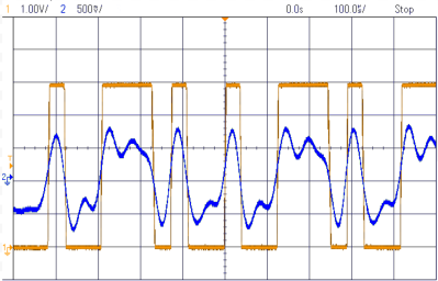
At first, it seemed like a simple task: any respectable phone’s DAC should have a sample rate of at least 44.1kHz. [David] used Oboe, a high performance C++ library for Android audio apps, to create the required waveform. The 8-bit data chunks he sent can only make up 256 unique messages, so he pre-generated them. However, the DAC tried to be clever and do some interpolation with the signal – great for audio, not so much for digital waveforms. You can see the warped signal in blue compared to what it should be in orange. To fix this, an op-amp comparator was used to clean up the signal, as well as boosting it to the required voltage.

Prefer your Arduino connections wireless? Check out this smartphone-controlled periodic table of elements, or this wireless robotic hand.

Hack a Day 31 May 09:00

Video of the Arduino FPGA Board Demo at Maker Faire

This week, Arduino announced a lot of new hardware including an exceptionally interesting FPGA development board aimed at anyone wanting to dip their toes into the seas of VHDL and developing with programmable logic. We think it’s the most interesting bit of hardware Arduino has released since their original dev board, and everyone is wondering what the hardware actually is, and what it can do.

This weekend at Maker Faire Bay Area, Arduino was out giving demos for all their wares, and yes, the Arduino MKR Vidor 4000 was on hand, being shown off in a working demo. We have a release date and a price. It’ll be out next month (June 2018) for about $60 USD.

But what about the hardware, and what can it do? From the original press releases, we couldn’t even tell how many LUTs this FPGA had. There were a lot of questions about the Mini PCIe connectors, and we didn’t know how this FPGA would be useful for high-performance computation like decoding video streams. Now we have the answers.

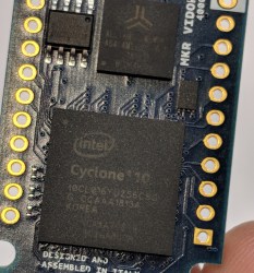
The FPGA on board the Arduino Vidor is an Altera Cyclone 10CL016. This chip has 16k logic elements, and 504 kB memory block. This is on the low end of Altera’s FPGA lineup, but it’s still no slouch. In the demo video below, it’s shown decoding video and identifying QR codes in real time. That’s pretty good for what is effectively a My First FPGA board.

Also on board the Vidor is a SAMD21 Cortex-M0+ microcontroller and a uBlox module housing an ESP-32 WiFi and Bluetooth module. This is a really great set of chips, and if you’re looking to get into FPGA development, this might just be the board for you. We haven’t yet seen the graphic editor that will be used to work with IP for the FPGA (for those who don’t care to write their own VHDL or Verilog), but we’re looking forward to the unveiling of that new software.

Arduino Just Introduced an FPGA Board, Announces Debugging and Better Software

Today ahead of the Bay Area Maker Faire, Arduino has announced a bevy of new boards that bring modern features and modern chips to the Arduino ecosystem.

Most ambitious of these new offerings is a board that combines a fast ARM microcontroller, WiFi, Bluetooth, and an FPGA. All this is wrapped in a package that provides Mini HDMI out and pins for a PCIe-Express slot. They’re calling it the Arduino MKR Vidor 4000.

Bringing an FPGA to the Arduino ecosystem is on the list of the most interesting advances in DIY electronics in recent memory, and there’s a lot to unpack here. FPGA development boards aren’t new. You can find crates of them hidden in the storage closet of any University’s electronics lab. If you want to buy an FPGA dev board, the Terasic DE10 is a good starter bundle, the iCEstick has an Open Source toolchain, and this one has pink soldermask. With the release of the MKR Vidor, the goal for Arduino isn’t just to release a board with an FPGA; the goal is to release a tool that allows anyone to use an FPGA.

The key to democratizing FPGA development is Arduino’s work with the Arduino Create ecosystem. Arduino Create is the company’s online IDE that gives everyone the ability to share projects and upload code with Over-the-Air updates. The MKR Vidor will launch with integration to the Arduino Create ecosystem that includes a visual editor to work with the pre-compiled IP for the FPGA. That’s not to say you can’t just plug your own VHDL into this board and get it working; that’s still possible. But Arduino would like to create a system where anyone can move blocks of IP around with a tool that’s easy for beginners.

A Facelift for the Uno WiFi

First up is the brand new Arduino Uno WiFi. While there have been other boards bearing the name ‘Arduino Uno WiFi’ over the years, a lot has changed in the world of tiny radio modules and 8-bit microcontrollers over the past few years. The new Arduino Uno WiFi is powered by a new 8-bit AVR, the ATMega4809. The ATMega4809 is a new part announced just a few months ago, and is just about what you would expect from the next-generation 8-bit Arduino; it runs at 20MHz, has 48 kB of Flash, 6 kB of SRAM, and it comes in a 48-pin package. The ATMega4809 is taking a few lattices of silicon out of Microchip’s playbook and adds Custom Configurable Logic. The CCL in the new ATMega is a peripheral that is kinda, sorta like a CPLD on chip. If you’ve ever had something that could be more easily done with logic gates than software, the CCL is the tool for the job.

But a new 8-bit microcontroller doesn’t make a WiFi-enabled Arduino. The wireless power behind the new Arduino comes from a custom ESP-32 based module from u-blox. There’s also a tiny crypto chip (Microchip’s ATECC508A) so the Uno WiFi will work with AWS. The Arduino Uno WiFi will be available this June.

But this isn’t the only announcement from the Arduino org today. They’ve been hard at work on some killer features for a while now, and now they’re finally ready for release. What’s the big news? Debuggers. Real debuggers for the Arduino that are easy to use. There are also new boards aimed at Arduino’s IoT strategy.

The Future of Arduino
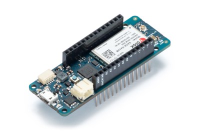
As you would expect in the world of embedded development, the future is IoT. Last week, Arduino announced the release of two new boards, the MKR WiFi 1010 and the MKR NB 1500. The MKR WiFi 1010 features a SAMD21 Cortex-M0+ microcontroller and a u-blox module (again featuring an ESP-32) giving the board WiFi. The MKR NB 1500 is designed for cellular networks and features the same SAMD21 Cortex-M0+ microcontroller found in the MKR WiFi 1010, but also adds a u-blox cellular module that will connect to LTE networks using Narrowband IoT, but the module does also support Cat M1 networks.

But IoT isn’t the only thing Arduino has been working on. On the leadup to the World Maker Faire this weekend, I had the opportunity to speak with Fabio Violante, CEO of Arduino, and Massimo Banzi, Co-founder of Arduino, and what I heard was remarkable. There’s going to be an update to the Arduino IDE soon, and real debugging is coming to the Arduino ecosystem. This is a significant development in Arduino’s software efforts, and when Fabio was appointed CEO last July, this was the first thing he wanted to do.

Also on deck for upcoming bits of hardware is a slow upgrade from ARM Cortex-M0 parts to Cortex-M4 parts. While this change isn’t exactly overdue, it is a direct result of the ever-increasing power of available microcontrollers. The reason for this change is the growing need for more compute power on embedded platforms, and simply the fact that more powerful chips are cheaper now.

Massimo, Fabio, and the rest of the Arduino team will be showing off their latest wares at Maker Faire Bay Area this weekend, and we will be posting updates. The FPGA Arduino — the MKR Vidor 4000 — will be on display running a computer vision demo, and there will, of course, be fancy new boards on hand. We’ll be posting updates so keep your eye on Hackaday!

Hack a Day 18 May 16:03

Reflowduino: Put That Toaster Oven To Good Use

There are few scenes in life more moving than the moment the solder paste melts as the component slides smoothly into place. We’re willing to bet the only reason you don’t have a reflow oven is the cost. Why wouldn’t you want one? Fortunately, the vastly cheaper DIY route has become a whole lot easier since the birth of the Reflowduino – an open source controller for reflow ovens.

This Hackaday Prize entry by [Timothy Woo] provides a super quick way to create your own reflow setup, using any cheap means of heating you have lying around. [Tim] uses a toaster oven he paid $21 for, but anything with a suitable thermal mass will do. The hardware of the Reflowduino is all open source and has been very well documented – both on the main hackaday.io page and over on the project’s GitHub.

The board itself is built around the ATMega32u4 and sports an integrated MAX31855 thermocouple interface (for the all-important PID control), LiPo battery charging, a buzzer for alerting you when input is needed, and Bluetooth. Why Bluetooth? An Android app has been developed for easy control of the Reflowduino, and will even graph the temperature profile.

When it comes to controlling the toaster oven/miscellaneous heat source, a “sidekick” board is available, with a solid state relay hooked up to a mains plug. This makes it a breeze to setup any mains appliance for Arduino control.

We actually covered the Reflowduino last year, but since then [Tim] has also created the Reflowduino32 – a backpack for the DOIT ESP32 dev board. There’s also an Indiegogo campaign now, and some new software as well.

If a toaster oven still doesn’t feel hacky enough for you, we’ve got reflowing with hair straighteners, and even car headlights.

Held Captive by Arduino and Multiple RFID Readers

If you’re the kind of person who has friends, and/or leaves the confines of the basement from time to time, we hear that these “Escape Rooms” are all the rage. Basically you get locked into a room with a couple other people and have to solve various problems and puzzles until you’ve finally made enough progress that they let you out. Which actually sounds a lot like the working conditions here at Hackaday HQ, except they occasionally slip some pizza rolls under the door for us which is nice.

Whichever side you find yourself on in one of these lighthearted hostage situations, knowledge of this multi-tag RFID lock created by [Annaane] may come in handy. By connecting multiple MFRC522 RFID readers to an Arduino Uno, she’s come up with a method of triggering a device (like an electronic door lock) only when the appropriate combination of RFID tags have been arranged. With a little imagination, this allows for some very complex puzzle scenarios which are sure to keep your prisoners enthralled until you can lower the lotion down to them.

Her code allows you to configure the type and number of RFID cards required to trigger one of the Arduino’s digital pins, which usually would be connected to a relay to fire off whatever device you want. The Arduino sketch is also setup to give “hints” to the player by way of a status LED: fast blinking let’s you know the tag scanned is wrong, and slow blinking means you don’t have enough scanned in yet.

The video after the break shows some highlights of the build, as well as a quick demonstration of how both the RFID “combination” and manual override can be used to trigger the attached relay.

Hackers do love RFID. Using them for physical access control is a fairly common project around these parts, and we’ve even seen similar setups for the digital realm.

A Two-Range OLED Capacitance Meter

If you are just starting out in electronics, you need tools. But it is hard to build all your tools. Even though we see a lot of soldering station builds, you really ought to have a soldering iron to build the station. It is hard to troubleshoot a multimeter you just built if you don’t have a multimeter. However, a capacitance meter is a handy piece of gear, relatively simple to build, and you should be able to get it working without an existing capacitance meter. [gavinlyonsrepo] presents a simple design using an Arduino, an OLED display, and a few components.

The principle of operation is classic. On one range, the Arduino charges the capacitor through one resistor and discharges it through another while timing the operation. The amount of time taken corresponds to the capacitance.

The other range doesn’t use external components but relies on the internal resistance of the Arduino and the stray capacitance in the chip and the board. Because these parameters vary, you’ll need to calibrate the device with a capacitor of known value.

This is one of those projects that would have been more complicated before microcontrollers. With an Arduino or similar device, though, it is pretty straightforward.

We looked at a project that explores the second method in depth quite some time ago. We’ve seen some similar meters in the past you might enjoy.

Push it to the Limit: SSD1306 at 150 FPS

A good deal of the projects we cover here at Hackaday are not, in the strictest sense, practical endeavors. If we required that everything which graced our digital pages had a clear end result, the site would be in a rather sad state of affairs. Sometimes it’s enough just to do something for the challenge of it. But more often than not, you’ll learn something in the process which you can use down the line.

That’s precisely what pushed [Laurence Bank] to see how well he could optimize the frame rate on the popular SSD1306 OLED display. After several iterations of his code, he was able to achieve a blistering 151.5 FPS, with apparently still some room for improvement if he’s feeling up to the challenge. But considering his first attempt was only running at 5.5 FPS, we’d say he’s already more than earned his hacker cred on this one.

A few different tricks were used to achieve such incredible performance gains. To start with, while the official I2C specification says you’re supposed to wait for an acknowledgment back from the device when communicating with it, [Laurence] realized the SSD1306 didn’t actually care. He could continuously blast commands at the display without bothering to wait for an acknowledgment. He admits there are problems with this method, but you can’t argue with the results.

To really wring all the performance out of the system he could, [Laurence] donned his Assembly Cap and examined how the Arduino IDE compiler was interpreting his code. He identified a few areas where changing his C code would force the compiler to generate faster output. He notes that this wouldn’t normally be required when working with more advanced compilers, but that the Arduino toolchain needs its hand held occasionally.

This isn’t the first time we’ve seen somebody try and push more pixels through the very same OLED display, and it’s interesting to see the two very different approaches to the same goal.

Stomping On Microcontrollers: Arduino Mega Guitar Effects Pedal

Effects pedals: for some an object of overwhelming addiction, but for many, an opportunity to hack. Anyone who plays guitar (or buys presents for someone who does) knows of the infinite choice of pedals available. There are so many pedals because nailing the tone you hear in your head is an addictive quest, an itch that must be scratched. Rising to meet this challenge are a generation of programmable pedals that can tweak effects in clever ways.

With this in mind, [ElectroSmash] are back at it with another open source offering: the pedalSHIELD MEGA. Aimed at musicians and hackers who want to learn more about audio, DSP and programming, this is an open-hardware/open-software shield for the Arduino MEGA which transforms it into an effects pedal.

The hardware consists of an analog input stage which amplifies and filters the incoming signal before passing it to the Arduino, as well as an output stage which does the DAC-ing from the Arduino’s PWM outputs, and some more filtering/amplifying. Two 8-bit PWM outputs are used simultaneously to make pseudo 16-bit resolution — a technique you can read more about in their handy forum guide.

The list of effects currently implemented covers all the basics you’d expect, and provides a good starting point for writing custom effects. Perhaps a library for some of the commonly used config/operations would be useful? Naturally, there are some computational constraints when using an Arduino for DSP, though it’s up to you whether this is a frustrating fact, or an opportunity to write some nicely optimised code.

[ElectroSmash] don’t just do pedals either: here’s their open source guitar amp.